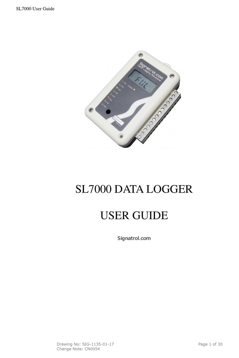
Signatrol Cadmus CTX-203 User manual

Document Reference: X-0036-01-07 Cadmus & Ratifi Operating Manual
Drawn: 13th November 2020
Page 1 of 66
Cadmus & Ratifi
Operating Manual.
The Ultimate Cloud Based Data Logging System

Document Reference: X-0036-01-07 Cadmus & Ratifi Operating Manual
Drawn: 13/11/2020
Page 2 of 66
Contents
GENERAL 4
1.1 OVERVIEW 4
1.1.1
About Signatrol 4
1.1.2
The System 4
1.1.3
The Manual 4
1.2 THE ADMINISTRATOR/USER MODEL 5
1.3 SECURITY 5
1.3.1
Introduction 5
1.3.2
WI-FI Connection 5
1.3.3
Data Security 5
INSTALLATION GUIDE 6
1.4 RECEIVING AND UNPACKING 6
1.5 CREATE RATIFI.CLOUD ACCOUNT 7
1.6 CREATE/ADD CLOUD PROJECT 9
1.7 ADDING THE DEVICE TO THE CLOUD 10
1.8 SETUP DEVICE CONFIGURATION 11
1.9 CONFIGURATION WIZARD 12
1.9.1
Main Tab. 12
1.9.2
Channel 1 (Internal Temperature). 13
1.9.3
Channel 2 (Internal Relative Humidity) (CTX-213 only) 14
1.9.4
Channel 3 and 4 (External Temperatures, Pt1000 sensor) 15
1.9.5
Channel 5 and 6 (Discrete Input) 16
1.9.6
LCD Display (CTX-203 and CTX-213 models only) 18
1.10 OPENING THE DEVICE ENCLOSURE. 19
1.10.1
CTX-203 and CTX-213 19
1.10.2
CTX-303 19
1.11 CONNECT EXTERNAL SENSORS 20
1.11.1
Connecting Pt1000 temperature sensors. 20
1.11.2
Connecting external digital output to discrete channels. 21
1.12 SETUP POWER SOURCE 22
1.13 USB CONFIGURATION VIA CADMUS-CONFIG 23
1.13.1
Installing Cadmus-Config 23
1.13.2
Loading Cadmus-Config 23
1.13.3
Connecting your device to the computer 23
1.13.4
Cadmus-Config basics 24
1.13.5
Cadmus-Config Information screen 25
1.13.6
Configuring Cadmus Security and Device Pin. 25
1.13.7
Cadmus-Config Settings Tab 27
1.13.8
External Temperature Sensor Tab 28
1.13.9
Battery Tab 28
1.13.10
Real Time Clock 29
1.13.11
Wi-Fi Connection 30
1.13.12
Wi-Fi Connection Wizard 31
1.13.13
WPA2- Personal Connection –Network Settings 33
1.13.14
WPA2-Enterprise Connection (EAP-TLS) –Network Settings. 35
1.14 PRODUCT POSITIONING 38
1.15 DEVICE AND CLOUD INTERACTION 39
1.16 ENTERING YOU COMPANY DETAILS. 39
1.17 ADD CLOUD USERS 40

Document Reference: X-0036-01-07 Cadmus & Ratifi Operating Manual
Drawn: 13/11/2020
Page 3 of 66
1.18 RATIFI CREDITS 41
RATIFI 43
1.19 RATIFI OVERVIEW 43
1.20 ADMINISTRATOR FUNCTIONS NOT ALREADY COVERED EARLIER. 44
1.20.1
Options 44
1.20.2
Automatic Reports 45
1.20.3
Auxiliary Admin email List 45
1.20.4
Audit Trails 46
1.21 EVENTS 46
2USER FUNCTIONS 47
2.1.1
Project Selection. 47
2.1.2
Overview 48
2.1.3
Devices 49
2.1.4
Health 50
2.1.5
Graph 51
2.1.6
Sensor Alarms 53
2.1.7
System Alarms 54
2.1.8
Export 54
2.1.9
Table Data 55
2.1.10
PDF Report 56
3HARDWARE SPECIFICATIONS@ 25°C 57
TROUBLE SHOOTING. 61
3.1 LCD ERROR MESSAGES 61
USEFUL INFORMATION 62
3.2 FIREWALLS 62
3.3 LOSS OF COMMUNICATION 62
3.4 LATE ALARMS 62
4REGULATORY INFORMATION RELATED TO WI-FI TRANSCEIVER. 63
4.1 RF FUNCTION AND FREQUENCY RANGE 63
4.2 EC 63
4.3 FCC AND IC CERTIFICATION. 64
4.3.1
FCC 64
4.3.2
CAN ICES-3(B) and NMB03(B) Certification and Statement 65
4.4 MIC CERTIFICATION (JAPAN) 65
4.5 SRRC CERTIFICATION AND STATEMENT (CHINA) 65
5SUPPORT AND CONTACTS 66

Document Reference: X-0036-01-07 Cadmus & Ratifi Operating Manual
Drawn: 13/11/2020
Page 4 of 66
General
1.1 Overview
1.1.1 About Signatrol
Signatrol is a UK based company who are experts in data logging solution with over 20 years of experience in the design, manufacture and sales of
Data Loggers and Data Logging systems, primarily for the food and pharmaceutical industries.
Our temperature data loggers are used in manufacture, storage, distribution and built environments to keep track of processes or comfort conditions
in buildings, offices and schools.
1.1.2 The System
The Cadmus is a Cloud Based Data Logging and Alarm Monitoring system. WI-FI enabled transmitters send data back to a cloud based operating
platform where the data are:
•Stored for subsequent analysis.
•Checked for alarm events
•Any alarm events are annunciated locally and sent, via email, to nominated people.
The system is essentially divided into three parts:
•Cadmus-Config, the Windows based configuration software to enable Cadmus devices to be configured and connected to the
appropriate WI-FI access point.
•Cadmus, the generic name of the WI-FI enabled data logging devices and related primarily to the hardware.
•Ratifi, the cloud based software that collects the data from one or more Cadmus devices, stores it in encrypted form, generates
automatic alarm event messages and allows the user to view and display the data in numerical or graphical form and the status of
any current alarms or events.
1.1.3 The Manual
Because of the power and scope of a Cadmus system this manual can, at first glance, seem a little daunting but the software has been
designed to be intuitive and therefore you should find setting up and operation quite straightforward. We are happy to provide telephone
assistance and regularly run Cadmus training sessions. Contact the office for details.

Document Reference: X-0036-01-07 Cadmus & Ratifi Operating Manual
Drawn: 13/11/2020
Page 5 of 66
1.2 The Administrator/User Model
Ratifi.cloud uses an Administrator/User model whereby the Administrator is the ‘Responsible Person’ within your organisation. He or she has sole
control of the system and sets up all the functionality. They can add and block users and enter all relevant data, alarm settings etc.
The user receives alarm messages (as determined by the Administrator) and can access the data but cannot implement any changes.
In addition to the administrator screens, the administrator can also access the user screens.
1.3 Security
1.3.1 Introduction
All data are stored in encrypted form that cannot be accessed by un-authorised persons. All data in the Cadmus/Ratifi cloud based data logging
system are protected to the highest standards and, rest assured, that whatever your security requirements we have a fully functional application to
suit your needs as follows:
1.3.2 WI-FI Connection
The WIFI connection is established using a variety of security protocols.
We recommend WPA2 Personal or, for the more demanding applications, WPA2 Enterprise.
1.3.3 Data Security
The data stored on the Ratifi cloud uses AES-256-CBC as the encryption method
The following data are encrypted:
First Name, Last Name, Contact Number, Email, Company Name, Department Name, VAT Number, Address

Document Reference: X-0036-01-07 Cadmus & Ratifi Operating Manual
Drawn: 13/11/2020
Page 6 of 66
Installation Guide
Receiving and Unpacking
Insert Power Link
Set Up ratifi.cloud Account*
Create/Add Project*
Add Cloud Users* Purchase* Tokens
Set Up Device using Cadmus-config *
Connect External Sensors
(If Required)
Add Device to Project*
Setup device cloud configuration*
* Available In Administrator Role.
1.4 Receiving and Unpacking
Congratulations you have just purchased the most comprehensive WI-FI enabled data logging and alarm monitoring system available today. Please
check the unit to ensure that it has arrived without damage. If there is any sign of damage, please contact your supplier. Cadmus is the product
name of the data logging hardware. Cadmus devices will always be used with our Cloud based software platform, Ratifi.
The packaging will contain the following:
•Cadmus device with pre-installed batteries, and in a powered down state.
•Quick-start information guide.

Document Reference: X-0036-01-07 Cadmus & Ratifi Operating Manual
Drawn: 13/11/2020
Page 7 of 66
1.5 Create ratifi.cloud account
Before setting up your device, you must first create a ratifi.cloud account.
Using your preferred web browser, go to URL: https://www.ratifi.cloud and then select “JOIN US”. Your email address will be used to validate the
new account.
Complete the form and then select “SUBMIT”.
Once the form has been submitted the administrator will receive an email.

Document Reference: X-0036-01-07 Cadmus & Ratifi Operating Manual
Drawn: 13/11/2020
Page 8 of 66
Click the link within the email and ratifi.cloud will open in your web browser. Create and enter your new password and then select “SAVE”.
Once the password has been set, Login to the administer section using your credentials.

Document Reference: X-0036-01-07 Cadmus & Ratifi Operating Manual
Drawn: 13/11/2020
Page 9 of 66
1.6 Create/Add Cloud Project
Under “PROJECTS” enter the new project details in the form as shown below.
Once the project has been created, click on the on the project line.

Document Reference: X-0036-01-07 Cadmus & Ratifi Operating Manual
Drawn: 13/11/2020
Page 10 of 66
1.7 Adding the device to the Cloud
Each Cadmus device is supplied with a registration card, which allows the administrator to register the device against their project. The project will
be credited (Free of Charge) 1 credit for each device registered. 1 credit will allow access for 1 device/month. The administrator will receive email
notification when your credits are running low. The registration card is only required once and can be disposed of after registration.
It is not required for the device to be connected to the Wi-Fi when the device configuration is setup. The cloud will store the configuration, and the
device will download the configuration as soon at it connects.
Enter the newly created project by selecting .
The “Add Devices” form will appear. Enter the serial number and device code into the boxes provided, and then select “SAVE”.
Note: Once the device code can only be used once. When removing a device from a project, the device will be automatically given a new device code
under “Removed Devices”.

Document Reference: X-0036-01-07 Cadmus & Ratifi Operating Manual
Drawn: 13/11/2020
Page 11 of 66
1.8 Setup Device Configuration
Select the “DEVICE CONFIGURATION” from the left hand menu (shown below).
The list of current devices allocated to the project will display. Select “Edit” (as shown below).
Note: Do not select “Remove”. Removing a device will remove the device from the current project. Refer to moving devices to another project in this manual.
Select from the pop-up how to configure your device.
SET DEVICE AS NEW
Load default settings into configuration wizard
COPY FROM EXISTING DEVICE
Load settings from another device into configuration wizard. Only available if more than 1
device is present in the project.
EDIT DEVICE
Load current settings into configuration wizard.
If you are configuring a new device select “SET THE DEVICE AS NEW”.

Document Reference: X-0036-01-07 Cadmus & Ratifi Operating Manual
Drawn: 13/11/2020
Page 12 of 66
1.9 Configuration Wizard
1.9.1 Main Tab.
The main tab contains parameters related to the general functionality of the Cadmus device.
Parameter Name
Description
Options
ENABLE/DISABLE
Changes the state of the Cadmus device
ON = Active Monitoring State , OFF = NAP mode
(device is sleeping)
In NAP mode the device will connect every 90
minutes to check if a new configuration packet has
been queued for the device on the cloud.
LOCATION
Location description text.
Maximum 32 characters. (e.g. Kitchen, Warehouse
1, Pharmacy, etc)
SERIAL NUMBER
Unique Factory set serial number.
Read Only.
MAC ADDRESS
Unique MAC address associated to the WiFi hardware within the device.
Read Only.
STORE RATE
Determines how often the device stores the sensor inputs to on-board memory. Default value = 10
minutes. The device has a fixed sample rate of 1 minute. If a sensor alarm occurs the device will store
the input within 60 seconds and force an upload, before returning to the configured store rate. So
irrespective of store rate, alarms will be notified within 60 seconds.
Available Settings.
1, 2, 3, 5, 10, 15, 30, 45, 50, 60 minutes.
UPLOAD RATE
Determines how often the device makes connection to a WiFi network and uploads its data to the cloud.
Default value = 30 minutes. If a sensor alarm occurs the device will connect within 60 seconds of the
alarm occurring, make its upload and then return to the configured upload rate.
Note. Ratifi has a built-in late alarm, which triggers if a device is not received. The default late alarm
period is 120 minutes. When configuring a device will a “UPLOAD RATE” >= 120 minutes. The “LATE
ALARM TRIGGER” should be extended. See section 1.20.1.
Available Settings.
5, 15, 30, 45, 60, 90, 120, 180, 360, 720, 1440
minutes.
CALIBRATION PERIOD
All devices contain the last calibration date. The device will automatically send reminders via the cloud
when calibration is less than 30 days away, and when the calibration expires.
Available Settings.
OFF, 6, 12, 18, 24, 36 months.
Setting OFF will disable all warnings.
AUDIBLE ANNUNCIATOR
When a sensor alarm is active the device will bleep an internal bleeper twice every 15 seconds.
OFF = bleeper disabled.
ON = bleeper active on sensor alarm.
RESET BATTERY LIFE
INDICATOR
All devices contain the date the internal batteries were last changed. Due to the battery technology
used it is not possible to monitor battery life based on the battery voltage, so a coulomb counting
method is implemented. For this method to accurately determine the battery state, the user must
inform the device when the batteries have been replaced.
NO = Do not send battery reset to device.
YES = Reset battery information and set battery
replaced date.
If a device is externally powered the device will
ignore the reset.
1.9.1.1 Battery Life Considerations.
The tables below give an estimated battery based on “Store Rate and Upload Rate” settings from +10 to +40°C ambient temperature for the device enclosure. Low
battery indicator email will trigger when 20% capacity has been reached. Note. Battery life will be reduced below the values stated before if the Wi-Fi network has
poor connection or there are a high number of sensor alarms occurring. Values below are only accurate when the device is fitted with new CADMUS-ACC-01 batteries
only.
Store Rate
Upload Rate
Battery Life
1 min
5 mins
0.28 years
1 min
15 mins
0.45 years
1 min
30 mins
0.52 years
5 mins
5 mins
0.43 years
5 mins
15 mins
0.96 years
5 mins
30 mins
1.39 years
Store Rate
Upload Rate
Battery Life
5 mins
60 mins
1.79 years
10 mins
30 mins
1.75 years
10 mins
60 mins
2.44 years
15 mins
15mins
1.18 years
15 mins
30 mins
1.92 years
15 mins
60 mins
2.77 years
Store Rate
Upload Rate
Battery Life
30 mins
30 mins
2.12 years
30 mins
60 mins
3.22 years
30 mins
120 mins
4.35 years
45 mins
45 mins
2.87 years
45 mins
90 mins
4.16 years
60 mins
60 mins
3.50 years

Document Reference: X-0036-01-07 Cadmus & Ratifi Operating Manual
Drawn: 13/11/2020
Page 13 of 66
1.9.2 Channel 1 (Internal Temperature).
The Channel 1 tab contains parameters related to
the internal temperature channel only.
On the CTX-203 and CTX-213 this sensor is
mounted under the lower vents as shown to the
right. This channel is ideally suited to monitoring
ambient office and warehouse temperatures,
which are slow changing. The CTX-303 also has
an internal temperature sensor but this is sealed
within the enclosure and has a slower response
time.
Parameter Name
Description
Options
TYPE
Internal Temperature
Read only.
CHANNEL NAME
Channel descriptor text.
16 Characters maximum.
ENABLE
Enable or Disable the channel.
ON or OFF
Sensor Alarms
The internal channel has 4 associated sensor alarms. 2 high alarms and 2 low alarms. The high high and low low alarm are given a higher priority in ratifi when
active, otherwise high high is handled the same as high, and low low is handled the same a low. Each of the 4 sensor alarms can be individually enabled or disabled,
with its own Setpoint. The channel has a hysteresis and alarm delay value which is common to all 4 sensor alarms.
Parameter Name
Description
Options
X ALARM ENABLE
Sensor alarm enabled or disabled.
ON or OFF
SETPOINT
Setpoint Temperature
Decimal value
X = HIGH HIGH, HIGH, LOW or LOW LOW.
High and High High Sensor Alarms.
Alarm active when last read value > Setpoint, alarm clears when last read value < (Setpoint - Hysteresis).
Low and Low Low Sensor Alarms.
Alarm active when last read value < Setpoint, alarm clears when last read value > (Setpoint + Hysteresis).
Hysteresis
Where the sensor alarm Setpoint determines when an alarm is raised, the hysteresis determines when an alarm clears. Using hysteresis reduces continuous alarming
when a sensor measurement is very close to the Setpoint value. The hysteresis can be set to 0.2, 0.5 or 1.0°C. For more information on hysteresis refer to the
hysteresis section. Recommended setting is 0.5°C.
Alarm Delay
The channel is sampled every 60 seconds, independent of the store rate. This gives a worse can alarm response < 60 seconds. The alarm delay maybe configured to
delay the alarm from triggering for up to 10 minutes. When an alarm is delayed the measurement must be continuously above/below the Setpoint for the indicated
time before the alarm triggered. If the measurement drops below / above the Setpoint before the indicated time the alarm will not be raised. This function is useful on
fridges or freezers where opening the door may cause a very short spike in air temperature.

Document Reference: X-0036-01-07 Cadmus & Ratifi Operating Manual
Drawn: 13/11/2020
Page 14 of 66
1.9.3 Channel 2 (Internal Relative Humidity) (CTX-213 only)
The Channel 2 tab contains parameters related to the
internal humidity channel only. This optional sensor is
mounted within the enclosure, approximately at the
position of the star. When mounted on a wall, air will
enter the enclosure as shown in the image to the right.
This channel is ideally suited to monitoring ambient
office and warehouse humidity, which are slow
changing.
Parameter Name
Description
Options
TYPE
Internal Humidity
Read only.
CHANNEL NAME
Channel descriptor text.
16 Characters maximum.
ENABLE
Enable or Disable the channel.
ON or OFF
Sensor Alarms
The internal channel has 4 associated sensor alarms. 2 high alarms and 2 low alarms. The high high and low low alarm are given a higher priority in ratifi when
active, otherwise high high is handled the same as high, and low low is handled the same a low. Each of the 4 sensor alarms can be individually enabled or disabled,
with its own Setpoint. The channel has a hysteresis and alarm delay value which is common to all 4 sensor alarms.
Parameter Name
Description
Options
X ALARM ENABLE
Sensor alarm enabled or disabled.
ON or OFF
SETPOINT
Setpoint % Relative Humidity
Decimal value
X = HIGH HIGH, HIGH, LOW or LOW LOW.
High and High High Sensor Alarms.
Alarm active when last read value > Setpoint, alarm clears when last read value < (Setpoint - Hysteresis).
Low and Low Low Sensor Alarms.
Alarm active when last read value < Setpoint, alarm clears when last read value > (Setpoint + Hysteresis).
Hysteresis
Where the sensor alarm Setpoint determines when an alarm is raised, the hysteresis determines when an alarm clears. Using hysteresis reduces continuous alarming
when a sensor measurement is very close to the Setpoint value. The hysteresis can be set to 0.2%, 0.5% or 1.0% RH. For more information on hysteresis refer to the
hysteresis section. Recommended setting is 1.0% RH.
Alarm Delay
The channel is sampled every 60 seconds, independent of the store rate. This gives a worse can alarm response < 60 seconds. The alarm delay maybe configured to
delay the alarm from triggering for up to 10 minutes. When an alarm is delayed the measurement must be continuously above/below the Setpoint for the indicated
time before the alarm triggered. If the measurement drops below/above the Setpoint before the indicated time the alarm will not be raised.

Document Reference: X-0036-01-07 Cadmus & Ratifi Operating Manual
Drawn: 13/11/2020
Page 15 of 66
1.9.4 Channel 3 and 4 (External Temperatures, Pt1000 sensor)
The Channel 3 and 4 tab contains parameters related to
external temperature channels only. Channel 3 and
Channel 4 are designed for RTD (Resistance Temperature
Detectors), type Pt1000 (Platinum, 1000 ohms at 0°C,
linearised to EN60751). The connection is 2 wire, and the
connection made via the side Jacks or base terminals.
Lead resistance compensation can be applied via the USB
Cadmus-Config software. Various probe assemblies are
available from Signatrol to cover the range -200 to
+400°C, with varying cable types and lengths.
Image shown are for CTX-203 and CTX-213, refer to
section 1.11.1 for more information and connecting to
CTX-303.
Parameter Name
Description
Options
TYPE
External Temperature
Read only.
CHANNEL NAME
Channel descriptor text.
16 Characters maximum.
ENABLE
Enable or Disable the channel.
ON or OFF
Sensor Alarms
The internal channel has 4 associated sensor alarms. 2 high alarms and 2 low alarms. The high high and low low alarm are given a higher priority in ratifi when
active, otherwise high high is handled the same as high, and low low is handled the same a low. Each of the 4 sensor alarms can be individually enabled or disabled,
with its own Setpoint. The channel has a hysteresis and alarm delay value which is common to all 4 sensor alarms.
Parameter Name
Description
Options
X ALARM ENABLE
Sensor alarm enabled or disabled.
ON or OFF
SETPOINT
Setpoint % Relative Humidity
Decimal value
X = HIGH HIGH, HIGH, LOW or LOW LOW.
High and High High Sensor Alarms.
Alarm active when last read value > Setpoint, alarm clears when last read value < (Setpoint - Hysteresis).
Low and Low Low Sensor Alarms.
Alarm active when last read value < Setpoint, alarm clears when last read value > (Setpoint + Hysteresis).
Hysteresis
Where the sensor alarm Setpoint determines when an alarm is raised, the hysteresis determines when an alarm clears. Using hysteresis reduces continuous alarming
when a sensor measurement is very close to the Setpoint value. The hysteresis can be set to 0.2°C, 0.5°C or 1.0°C. For more information on hysteresis refer to the
hysteresis section. Recommended setting is 0.5°C.
Alarm Delay
The channel is sampled every 60 seconds, independent of the store rate. This gives a worse can alarm response < 60 seconds. The alarm delay maybe configured to
delay the alarm from triggering for up to 10 minutes. When an alarm is delayed the measurement must be continuously above/below the Setpoint for the indicated
time before the alarm triggered. If the measurement drops below/above the Setpoint before the indicated time the alarm will not be raised.

Document Reference: X-0036-01-07 Cadmus & Ratifi Operating Manual
Drawn: 13/11/2020
Page 16 of 66
1.9.5 Channel 5 and 6 (Discrete Input)
Parameter Name
Description
Options
TYPE
discrete Interrupt/Counter
Read only.
CHANNEL NAME
Channel descriptor text.
16 Characters maximum.
CONFIG
Select channel mode
OFF, Discrete or Counter.
Channels 5 and 6 can function in two different modes.
•Counter mode
The device will count pulses applied to the input connection. The device will then scale the counts into engineering units (example kWh) and store the
scaled value. The scaled unit is based on the total counts per “store rate” period. If the requirement is to monitor energy using in kWh, the store rate
should be set to 60 minutes.
•Discrete mode
The device will monitor the input as either a high or low state. The status of the input is sampled when the other sensor inputs are sampled (this mode is
called polling), if the setting “INTERRUPT FORCES READ AND UPLOAD” is enabled, it will force the device to instantly store the changed state and upload to
the cloud. When the setting is disabled the input works as a polled input. When polled any changes on the input condition where occur when the device is
not sampling (once every 60 seconds) will be missed. Generally polled input is only useful when the status of the input is slow changing and stays in the
same state for more than 60 seconds, an advantage of this mode is the device remains in low power mode longer and this improves battery life. When the
discrete input is set to “INTERRUPT FORCES READ AND UPLOAD” an additional setting allows the setting of the interrupt edge type.
Example: If a magnetic door switch is fitted to a fridge, and the interrupt set to both edges. The device will read and upload when the door is opened and
closed.
Note: The interrupt event does not re-sample the sensor inputs (channels 1 to 4). If it has been > 30 seconds since the last sensor read, the system will
wake and update channels 1 to 4 (as appropriate) before uploading; otherwise the previous channels values will be used. If an interrupt occurs a few
seconds before a scheduled sample the upload will be delayed by a few seconds to get the latest sensor inputs values.
There are no alarms available on channels 5 and 6.
For full electrical specification of the discrete input see the hardware specification.

Document Reference: X-0036-01-07 Cadmus & Ratifi Operating Manual
Drawn: 13/11/2020
Page 17 of 66
1.9.5.1 Counter Mode Configuration
Parameter Name
Description
Options
ELECTRICAL HIGH
Maximum counts per “Store Rate” period.
0 to 65535, integer value. *note 1
ELECTRICAL LOW
Minimum counts per “Store Rate” period.
0 to 65535, integer value *note 1
ENGINEERING HIGH
Engineering value equating to “ELECTRICAL HIGH” counts.
Decimal number.
ENGINEERING LOW
Engineering value equating to “ELECTRICAL LOW” count.
Decimal number.
ENGINEERING UNITS
Unit associated with the engineering value. e.g. kWh
Maximum 5 characters.
*Note 1: Maximum input frequency 1kHz.
When selecting the “store rate” for the device ensure, the electrical counts do not exceed 65535, and the maximum frequency does not exceed 1kHz.
Example: To monitor power consumption, if the “store rate” is set to 60 minutes, this means the counts cannot exceed 65535 counts in 60 minutes.
1.9.5.2 Interrupt Mode Configuration
Parameter Name
Description
Options
INTERRUPT FORCES UPLOAD
When OFF discrete is sampled every 60 seconds.
When ON discrete is sample every 60 seconds, and forces upload
then interrupt status is changed.
OFF, ON
INTERRUPT EDGE
Only visible when “INTERRUPT FORCES READ AND UPLOAD” = ON.
Determines what interrupt states cause upload.
FALLING EDGE, RISING EDGE, BOTH EDGES.

Document Reference: X-0036-01-07 Cadmus & Ratifi Operating Manual
Drawn: 13/11/2020
Page 18 of 66
1.9.6 LCD Display (CTX-203 and CTX-213 models only)
Devices fitted with displays can be configured to
display channels 1 to 4. The configuration wizard will
only allow enabled channels to be shown on the main
or sub displays. If more than 1 channel is enabled, the
device will automatically scan the selected channels.
The time zone will show current local time or time to
next upload.

Document Reference: X-0036-01-07 Cadmus & Ratifi Operating Manual
Drawn: 13/11/2020
Page 19 of 66
1.10 Opening the device enclosure.
1.10.1 CTX-203 and CTX-213
To open the device enclosure, use a narrow flat screwdriver to release the two clips shown above. To close the enclosure, locate the top edge of the
enclosure over the base and then push down.
1.10.2 CTX-303

Document Reference: X-0036-01-07 Cadmus & Ratifi Operating Manual
Drawn: 13/11/2020
Page 20 of 66
1.11 Connect External Sensors
Base Connections
1.11.1 Connecting Pt1000 temperature sensors.
Channels 3 and 4 are designed for 2-wire Pt1000 sensors. These sensors can be purchased directly from Signatrol Ltd. There are two connection methods for Pt1000
sensors show below. Pt1000 sensor are non-polarised and be connected either way around. If a sensor is disconnected or becomes open-circuit the channel will
indicate +400°C (+752°F), if a sensor becomes short-circuit the channel will indicate -200°C (-328°F). Sensors should be connected via the Jack or the Terminal
strip, but not to both at the same time on the same channel. Otherwise incorrect readings will be obtained.
CTX-203 and CTX-213 models
Connection via 3.5mm jack plugs.
Channel 3 = Black (Upper) socket.
Channel 4 = Turquoise (Lower) socket.
Sensors supplied with jack connectors will be supplied with a loose Turquoise cover
label, this should be applied if the sensor is connected to Channel 4.
Connection via enclosure base terminal strip.
Channel 3 should be connected to pins 1 & 2.
Channel 4 should be connected to pins 3 & 4.
Wire colours are only a guide. Wire colours may change depending on manufacturer.
CTX-303 model
Connection via enclosure base terminal strip.
Channel 3 should be connected to pins 1 & 2.
Channel 4 should be connected to pins 3 & 4.
Wire colours are only a guide. Wire colours may change depending on manufacturer.
Connector lifts off pin header for easy connection.
This manual suits for next models
1
Table of contents
Other Signatrol Data Logger manuals
Popular Data Logger manuals by other brands
process-informatik
process-informatik EtherSens Energy Handling-Short Instruction
Elster Instromet
Elster Instromet DL230 operating manual
LR-Cal
LR-Cal LDM 80 Series operating manual
Avisaro
Avisaro M41076 quick guide
Microedge Instruments
Microedge Instruments iLog Series user manual
VOLTCRAFT
VOLTCRAFT VC-655 BT operating instructions
