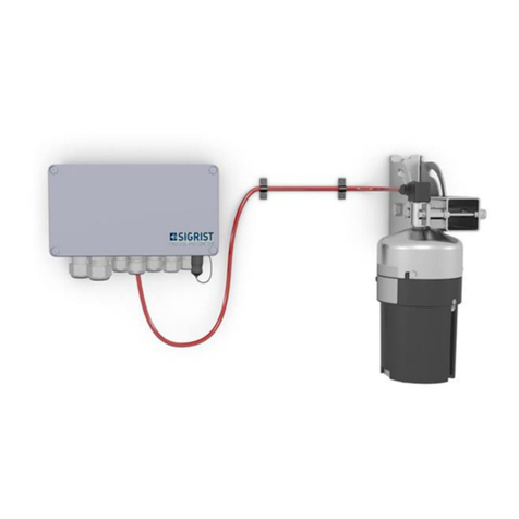
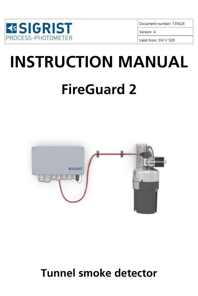
SIGRIST FireGuard 2 Integral User manual

Pos: 2/ Steuermodule/Titels eite Kopf @ 0\mod_134147 6551542_20.docx @ 3531 @ @ 1
Document number: 13763E
Version: 1
Valid from: S/N 733010 /
SW V528
INSTRUCTION MANUAL
FireGuard 2 Integral
Pos: 3/Ti telbilder/Fire Guard 2/Titelbild FireG uard 2 Integral @ 4\m od_14551966498 14_0.docx @ 23414 @ @ 1
Pos: 4/ Steuermodule/Ti telseite Geräteart @ 0\mod_134 1476758775_20.doc x@ 353 5@ @ 1
Tunnel smoke detector
Pos: 5/---S eitenumbruch--- @ 0\m od_1341482862121 _0.docx @ 4073 @ @ 1
Pos: 6/ Steuermodule/Co pyright @ 0\mod_13414799 46098_20.docx @ 4060 @ @ 1

Copyright© SIGRIST-PHOTOMETER AG, subject to technical changes without notice 4/2017
Pos: 7/ Steuermodule/A dressblock @ 0\mod_13414 80540857_20.doc x@ 4064 @ @ 1
SIGRIST-PHOTOMETER AG
Hofurlistrasse 1
CH-6373 Ennetbürgen
Switzerland
Tel. +41 41 624 54 54
Fax +41 41 624 54 55
info@photometer.com
www.photometer.com
=== Ende der Liste für Te xtmarke Titelseite ===

Contents Instruction Manual FireGuard 2 Integral
13763E/1 3
Pos: 9/ Steuermodule/Inh altsverzeichnis 1-3 @ 1\mod_ 1370269934450_20.d ocx @ 12319@ @ 1
Contents
1General user information...............................................................................................7
1.1 Terms used in this document (glossary) .............................................................7
1.2 Purpose of the Instruction Manual ....................................................................7
1.3 Target group of the documentation..................................................................7
1.4 Additional documentation ................................................................................7
1.5 Copyright provisions .........................................................................................7
1.6 Document storage location...............................................................................7
1.7 Order document ...............................................................................................8
1.8 Proper use ........................................................................................................8
1.9 User requirements ............................................................................................8
1.10 Declaration of conformity .................................................................................8
1.11 Use restrictions .................................................................................................8
1.12 Dangers when not used properly ......................................................................9
1.13 Meaning of the safety symbols .........................................................................9
1.14 Meaning of the pictograms.............................................................................10
2Instrument overview ....................................................................................................11
2.1 Overview of a measuring point .......................................................................11
2.2 Designation of the components ......................................................................12
2.2.1 Rating plate on FireGuard 2 Integral ..........................................................12
2.2.2 Rating plate on SICON-C ...........................................................................13
2.3 Scope of supply and accessories......................................................................14
2.4 Technical data for the FireGuard 2 Integral .....................................................16
3General safety points...................................................................................................18
3.1 Dangers when properly used ..........................................................................18
3.2 Residual risk....................................................................................................19
3.3 Warning and danger symbols on the instrument.............................................19
3.4 Preventing undesirable online access attempts................................................20
4Mounting ....................................................................................................................21
4.1 General information on mounting the FireGuard 2 Integral ............................21
4.2 Mounting the V2 junction box........................................................................22
5Electrical installation ....................................................................................................23
5.1 Safety pointers for the electrical connection....................................................23
5.2 Connecting the FireGuard 2 Integral to the V2 junction box ...........................24
5.3 Profibus DP: Overview and installation ............................................................26
5.4 Modbus RTU with repeater: Overview and installation ....................................27
5.5 StromRel module: Overview and installation ...................................................29
5.6 Removing the electronics housing...................................................................30
6Commissioning............................................................................................................31

Instruction Manual FireGuard 2 Integral Contents
4 13763E/1
7Operation ....................................................................................................................32
7.1 Operation basics .............................................................................................32
7.2 LED display on the photometer .......................................................................32
7.3 Connecting the SICON-C to the FireGuard 2 Integral ......................................34
7.4 Control elements in measuring operation .......................................................35
7.5 Menu button ..................................................................................................35
7.6 Valu button ....................................................................................................35
7.7 Info button .....................................................................................................36
7.7.1 Page 1 Info button ....................................................................................36
7.7.2 Page 2, Info button ...................................................................................37
7.8 Display in measuring operation .......................................................................38
7.9 Activating and deactivating the screen lock ....................................................39
7.10 Switching to service mode ..............................................................................40
7.11 Control components in service mode ..............................................................41
7.11.1 Input elements in service mode..................................................................41
7.11.2 Numerical entry .........................................................................................42
7.11.3 Single selection of functions ......................................................................43
7.11.4 Multiple selection of functions...................................................................43
8Settings .......................................................................................................................44
8.1 Setting the operating language.......................................................................44
8.2 Configuring the limits .....................................................................................45
8.2.1 General information on setting the limits...................................................45
8.2.2 Setting the limits........................................................................................46
8.2.3 How a limit is formed ................................................................................47
8.2.4 Defining the cut-in delay ...........................................................................48
8.2.5 Defining the cut-out delay .........................................................................49
8.2.6 Calculating the gradient ............................................................................50
8.2.7 Reading if limit exceeded or undershot ......................................................50
8.3 Setting the outputs for limit monitoring..........................................................51
8.3.1 General information on limit monitoring ...................................................51
8.3.2 Mode 1 .....................................................................................................51
8.3.3 Mode 2 (factory setting) ............................................................................52
8.3.4 Setting the outputs....................................................................................53
8.4 Setting the recalibration..................................................................................54
8.5 Setting the Profibus parameters ......................................................................55
8.6 Setting the Modbus parameters......................................................................56
8.7 Setting the current outputs.............................................................................57
8.8 Setting or changing the access code ...............................................................58
8.9 Backup configured data..................................................................................59
9Servicing......................................................................................................................60
9.1 Servicing schedule ..........................................................................................60
9.2 Cleaning the measuring cell............................................................................61
9.3 Cleaning the optics.........................................................................................67
9.4 Recalibrating the FireGuard 2 Integral .............................................................69
9.4.1 General information on recalibrating the FireGuard 2 Integral ...................69
9.4.2 Setting checking unit number in use..........................................................69
9.4.3 Manual adjustment with a SICON-C ..........................................................70
9.4.4 Automatically triggered adjustment without SICON-C ...............................72
9.5 Changing the battery in the control unit.........................................................74

Contents Instruction Manual FireGuard 2 Integral
13763E/1 5
10 Troubleshooting ..........................................................................................................75
10.1 Pinpointing malfunctions ................................................................................75
10.1.1 Warning messages and effect on operation...............................................75
10.1.2 Fault messages and effect on operation.....................................................77
10.1.3 Prioritized fault messages and their effect on operation.............................78
11 Customer service information ......................................................................................79
12 Decommissioning/storage............................................................................................80
12.1 Decommissioning the photometer ..................................................................80
12.2 Storing the photometer ..................................................................................80
13 Packaging/Transport/Returning ....................................................................................81
14 Disposal.......................................................................................................................82
15 Spare parts list .............................................................................................................83
16 Appendix.....................................................................................................................84
16.1 Disassembly diagram for the FireGuard 2 Integral ...........................................85
17 Index ...........................................................................................................................87
=== Ende der Liste für Te xtmarke Inhaltsverzeich nis== =

Instruction Manual FireGuard 2 Integral Contents
6 13763E/1
This pageis i ntentionally blank

General user information Instruction Manual FireGuard 2 Integral
13763E/1 7
Pos: 11 /Allgemeine B enutzerinformation en/Titel 1_Allgemei neB enutzerinfor mationen @ 0\mod_134 1410540928_20 .docx @ 3177 @ 1 @ 1
1General user information
Pos: 12 /Allgemeine Benutzerin formationen/Ver wendeteF achbegriffe (Glossar) @ 0\ mod_134554190 9056_20.docx @ 5429 @ 2@ 1
1.1 Terms used in this document (glossary)
Please refer to our website for specialist terms: www.photometer.com/de/abc/index.html
Pos: 13 /Allgemeine B enutzerinformation en/Zweck der Doku mentation/Zwec kder B etriebsanleitung @ 0\mod_1350635852749 _20.docx @ 7700 @ 2 @ 1
1.2 Purpose of the Instruction Manual
This Instruction Manual provides the user with helpful information about the entire life cycle
of the FireGuard 2 Integral and its peripheral devices. Before commissioning the instrument,
you should be completely familiar with the Instruction Manual.
Pos: 14 /Allgemeine B enutzerinformation en/Zielgruppe der Doku mentation/Zielg ruppe derD okumentati on( Betriebsanleitung) @ 0\mod_135063676 7781_20.docx @ 7 706 @ 2 @1
1.3 Target group of the documentation
The Instruction Manual is intended for all persons who are responsible for the operation and
maintenance of the instrument.
Pos: 15 /Allgemeine B enutzerinformatio nen/Weiterführen deD okumentation/Fir eGuard 2/Weiterfü hrendeD okumentati onF ireGuard 2 Integral B A @4 \mod_1455 196686199_20.doc x@ 2 3421 @ 2 @ 1
1.4 Additional documentation
DOC. NO.
TITLE
CONTENT
13544E
Brief Instructions
The most important functions and the servicing
schedule.
13779E
Reference Manual
More sophisticated menu functions and worksteps
for advanced users.
13654E
Data Sheet
Descriptions and technical data about the instru-
ment.
13764E
Service Manual
Repair and conversion instructions for service engi-
neers.
14173DEF
Declaration of Confor-
mity
Compliance with the underlying directives and
standards.
Pos: 16 /Allgemeine B enutzerinformation en/Urheberrechtlic heB estimmungen @ 0\ mod_134141 0541182_20.doc x@ 3 193 @ 2@ 1
1.5 Copyright provisions
This document has been written by SIGRIST-PHOTOMETER AG. Copying or modifying the
content or giving this document to third parties is permitted only with the express consent of
SIGRIST-PHOTOMETER AG.
Pos: 17 /Allgemeine Benutzerin formationen/Auf bewahrungsort der Dokume nte/Aufbewahrungsort des Doku ments@ 0 \mod_1348219 874459_20.doc x@ 6821 @ 2 @ 1
1.6 Document storage location
This document is part of the product. It should be stored in a safe place and always be close
at hand for the user.
Pos: 18 /---Seitenumbruch--- @ 0\ mod_134148286212 1_0.docx @ 4073 @ @ 1

Instruction Manual FireGuard 2 Integral General user information
8 13763E/1
Pos: 19 /Allgemeine Benutzerin formationen/Nach bestellung desD okuments @ 0\mo d_1341410541249_ 20.docx @ 3197 @ 2@ 1
1.7 Order document
The most recent version of this document can be downloaded at www.photometer.com
(first time registration required).
It can also be ordered from a SIGRIST representative in your country (Instruction Manual
“Customer service information”).
Pos: 20 /Allgemeine B enutzerinformation en/Bestimmungsge mässe Verwendung/ Bestimmungsge mässe Verwendung Fire Guard 2 @ 4\ mod_143582438899 9_20.docx @ 21100 @ 2 @ 1
1.8 Proper use
The photometer and its peripherals are designed for detecting smoke in tunnels at ambient
temperatures of between -20 °C (minimum) and +50 °C (maximum).
Pos: 21 /Allgemeine B enutzerinformation en/Benutzeranfor derungen @ 0\mod_ 1348478183397 _20.docx @ 6856 @ 2 @ 1
1.9 User requirements
The instrument may be operated only by trained technical personnel who have read and un-
derstood the content of the Instruction Manual.
Pos: 22 /Allgemeine B enutzerinformation en/Konformitätser klärung @ 0\mod_ 1348479046232_ 20.docx @ 6861 @ 2 @ 1
1.10 Declaration of conformity
Current technological principles were followed in designing and manufacturing the instru-
ment. They comply with the applicable guidelines concerning safety and duty to take due
care.
EU: The measuring instrument meets all applicable requirements within the European Union
(EU) for carrying the CE mark.
Please refer to the separate declaration of conformity for details. Section 1.4
Pos: 23 /Allgemeine B enutzerinformation en/Einschrän kung derA nwendung/Einsc hränkung der Anwen dung nicht Ex @ 0\ mod_134848931791 2_20.docx @ 6872 @ 2 @ 1
1.11 Use restrictions
EXPLOSION
HAZARD!
Operation in an inappropriate environment.
Use in explosive areas can cause explosions, which can lead to the death of persons in the
vicinity.
It is not permitted to operate the instrument in explosion hazardous areas or rooms.
It is not permitted to use the instrument with explosive sample substances.
Pos: 24 /---Seitenumbruch--- @ 0\ mod_134148286212 1_0.docx @ 4073 @ @ 1

General user information Instruction Manual FireGuard 2 Integral
13763E/1 9
Pos: 25 /Allgemeine B enutzerinformation en/Gefährdungen bei _nicht_best_Ver wendung/Gefähr dungen bei nicht bestimm ungs¬gemässer Verwendung @ 0\mod_13 48490023905_2 0.docx @ 6877 @ 2 @ 1
1.12 Dangers when not used properly
DANGER!
Operation when not used properly.
Improper use of the instrument can cause injuries to persons, process-related consequential
damage and damage to the instrument and its peripherals.
In the following cases the manufacturer cannot guarantee the protection of persons and the
instrument and therefore assumes no legal responsibility:
The instrument is used in a way not included in the described area of application.
The instrument is not properly mounted or set up.
The instrument is not installed and operated in accordance with the Instruction Manual.
The instrument has been operated with accessory parts which SIGRIST-PHOTOMETER
AG has not expressly recommended.
Improper changes to the instrument have been performed.
The instrument has not been operated within the specifications, in particular concerning
pressure and temperature.
Pos: 26 /---Seitenumbruch--- @ 0\ mod_134148286212 1_0.docx @ 4073 @ @ 1
Pos: 27.1 /Allgemeine Benutzeri nformationen/Bede utung der Sicherheitssymbol e/Titel 2_Bedeutung der Sicher heitssymbole @ 1\mod_1 361351807227_20. docx@ 10 646 @ 2@ 1
1.13 Meaning of the safety symbols
All danger symbols used in this document are explained below:
Pos: 27.2 /Allgemeine B enutzerinformatio nen/Bedeutung der Sic herheitssymbol e/Sicherheitss ymbol-Gefahr durch Str omschlag @ 1\mod _1361351826717 _20.docx @ 10652 @ @ 1
DANGER!
Danger due to electrical shock that may result in serious bodily injury or death.
Non-observance of this danger warning may lead to electrical shocks and death.
Pos: 27.3 /Allgemeine Benutzeri nformationen/Bede utung der Sicherheitssymbol e/Sicherheitss ymbol_Explosionsgefa hr@ 1\ mod_136135183 0303_20.docx @ 10658 @ @ 1
EXPLOSION
HAZARD!
Danger due to explosion that may result in serious bodily injury or death.
Non-observance of this notice may cause explosions resulting in serious property damage
and death.
Pos: 27.4 /Allgemeine B enutzerinformatio nen/Bedeutung der Sic herheitssymbol e/Sicherheitss ymbol_Warnung @ 1\ mod_1361351833 084_20.docx @ 106 64@ @ 1
WARNING!
Warning about bodily injury or hazards to health with long-term effects.
Non-observance of this warning may lead to injuries with possible long-term effects.
Pos: 27.5 /Allgemeine Benutzeri nformationen/Bede utung der Sicherheitss ymbole/Sicherheitss ymbol_Vorsicht @ 1\mod_1 361351836622_20.doc x@ 106 70@ @ 1
CAUTION!
Notice about possible material damage.
Non-observance of this notice may cause material damage to the instrument and its
peripherals.

Instruction Manual FireGuard 2 Integral General user information
10 13763E/1
Pos: 28.1 /Allgemeine B enutzerinform ationen/Bedeutung der Pict ogramme/Titel 2 Be deutung der Piktogr amme @ 1\mod_13 61350393237_20.d ocx @ 10599 @ 2 @ 1
1.14 Meaning of the pictograms
All pictograms used in this document are explained below:
Pos: 28.2 /Allgemeine B enutzerinform ationen/Bedeutung der Pict ogramme/Pi ktogramm Info @ 1\ mod_1361350418 070_20.docx @ 10605 @ @ 1
Additional information about the current topic.
Pos: 28.3 /Allgemeine B enutzerinformatio nen/Bedeutung der Pict ogramme/Pi ktogramm praktisch erAr beitsvorgang @ 1\mod_1361350426620 _20.docx @ 10617 @ @ 1
Practical procedures when working with the FireGuard 2 Integral.
Pos: 28.4 /Allgemeine B enutzerinformatio nen/Bedeutung der Pict ogramme/Pi ktogramm_Manipilati ona mT ouchscreen @ 1 \mod_13629 91598679_20.doc x@ 10909@ @ 1
Manipulations on the touchscreen.
Pos: 28.5 /Allgemeine B enutzerinformatio nen/Bedeutung der Pict ogramme/Pi ktogramm_Symbolbil d @ 5\mod_1485 442354911_20.doc x @ 31877 @ @ 1
The screenshot is an example and may differ from current device.
Pos: 29 /---Seitenumbruch--- @ 0\ mod_134148286212 1_0.docx @ 4073 @ @ 1

Instrument overview Instruction Manual FireGuard 2 Integral
13763E/1 11
Pos: 30 /Geräteübersicht Kapitel BA /Titel1 G eräteübersicht @ 0\mod _1349186174116_20. docx @ 6951@ 1 @ 1
2Instrument overview
Pos: 31 /Geräteübersic ht Kapitel BA/Gerä teübersicht/FireG uard 2/Geräteüb ersichtei ner Messstelle Fir eGuard 2 Integral @ 4\ mod_1455274691 285_20.docx @ 23456 @ 2@ 1
2.1 Overview of a measuring point
Figure 1: Overview of a measuring point
V2 junction box
FireGuard 2 Integral photometer (smo-
ke detector)
SICON-C portable control unit, can
be connected to the FireGuard 2
Integral via cable
Pos: 32 /---Seitenumbruch--- @ 0\ mod_134148286212 1_0.docx @ 4073 @ @ 1

Instruction Manual FireGuard 2 Integral Instrument overview
12 13763E/1
Pos: 33 /Geräteübersicht Kapitel BA /Typenschild_Ke nnzeichnung/Kennzeic hnung der Komponenten @ 4\ mod_1442233646926_ 20.docx @ 21670 @ 2@ 1
2.2 Designation of the components
Pos: 34 /Geräteübersic ht Kapitel BA/Typensc hild_Kennzeichn ung/FireGuard 2/Typ enschild Fir eGuard 2I ntegral @ 4\mod _1455196880013 _20.docx @ 23428 @ 3 @ 1
2.2.1 Rating plate on FireGuard 2 Integral
The FireGuard 2 Integral photometer is fitted with the following rating plate:
Figure 2: Rating plate on FireGuard 2 Integral
Manufacturer
Country of origin
Product name
Serial number
Date of manufacture
Service voltage
Frequency range
Power
Observe the Instruction Manual
Observe the disposal information
A red sticker is attached to the FireGuard 2 Integral (arrow).
This distinguishes it from the first version FireGuard.
Figure 3: Red sticker for identifying the FireGuard 2 Integral
Pos: 35 /---Seitenumbruch--- @ 0\ mod_134148286212 1_0.docx @ 4073 @ @ 1
Pos: 36 /Geräteübersicht Kapitel BA /Typenschild_Ke nnzeichnung/Typensc hildSIC ON-C @ 4\mod_1442 233682176_20.docx @ 21 691@ 3 @ 1

Instrument overview Instruction Manual FireGuard 2 Integral
13763E/1 13
2.2.2 Rating plate on SICON-C
The SICON-C portable control unit is fitted with the following rating plate:
Figure 4: Rating plate on SICON-C
Manufacturer
Country of origin
Product name
Serial number
Date of manufacture
Service voltage
Frequency range
Power
Observe the Instruction Manual
Observe the disposal information
Pos: 37 /---Seitenumbruch--- @ 0\ mod_134148286212 1_0.docx @ 4073 @ @ 1

Instruction Manual FireGuard 2 Integral Instrument overview
14 13763E/1
Pos: 38 /Geräteübersic ht Kapitel BA/Lieferu mfang/Lieferumfa ngFi reGuard 2 Integral @ 4\ mod_145519 7031926_20.doc x@ 2 3435 @ 2 @ 1
2.3 Scope of supply and accessories
Standard scope of supply for the FireGuard 2 Integral:
PCS.
ART. NO.
NAME
VIEW
VARIANT
1
120300
FireGuard 2 Integ-
ral with cable
0.9 m
1
120305
Profibus DP inter-
faces module
120306
StromRel
interfaces module
120307
Modbus RTU
interfaces module
1
120455
Mounting bracket

Instrument overview Instruction Manual FireGuard 2 Integral
13763E/1 15
Attached documents:
PCS.
DOC. NO.
NAME
VIEW
VARIANT
1
13763
Instruction Manual
German
French
English
1
13779
Reference Manual
German
English
1
13544
Brief Instructions
German
French
English
Optional accessory parts:
PCS.
ART. NO.
NAME
VIEW
VARIANT
1
120309
WLAN module
1
117396
Sample heater,
pair
1
120290
SICON-C portable
control unit
1
120345
V2 junction box
1
117390
Checking unit

Instruction Manual FireGuard 2 Integral Instrument overview
16 13763E/1
PCS.
ART. NO.
NAME
VIEW
VARIANT
1
120308
Tool-free mainte-
nance
The instruments can
be equipped with
knurled screws (opti-
onal).
Pos: 39 /---Seitenumbruch--- @ 0\ mod_134148286212 1_0.docx @ 4073 @ @ 1
Pos: 40 /Geräteübersic ht Kapitel BA/Technisc he Daten/FireGuar d 2/Technisch eD aten FireGuard 2 Integral @ 4\mod_14552742517 67_20.docx @ 23449 @ 2 @ 1
2.4 Technical data for the FireGuard 2 Integral
General:
Data
Values
Measuring principle
Scattered light measurement
Measurement span
0 .. 3 E/m
Wavelength
670 nm
Resolution
± 0.001 E/m
Reproducibility
± 0.001 E/m, or 2 % of the measuring range
Reaction time
5 s (at a wind speed of 1.5 m/s)
Measuring angle
120 °
Ambient temperature
-20 .. 50 °C
Ambient humidity
0 .. 100 % rel. humidity
FireGuard 2 Integral photometer:
Data
Values
Service voltage
100 .. 240 VAC; 47 .. 63 Hz
Power consumption
Sample heater OFF: 5 W/14 VA
Sample heater ON: 19 W/33 VA
Weight
2.1 kg (2.3 kg with sample heater)
Protection class
IP66 (electronics only)
Photometer material
Stainless steel 1.4571 (316L)
Measuring cell material
PC/ABS
Interfaces
Profibus DP, Modbus RTU with repeater, StromRel module, WLAN
module
Cable for V2 junction
box
Length: 0.9 m
Dimensions
ca. Ø 150 mm x 186 mm x 247 mm
Detailed dimension sheet Section 16

Instrument overview Instruction Manual FireGuard 2 Integral
13763E/1 17
SICON-C portable control unit:
Data
Values
Service voltage
24 VDC
Power consumption
1.3 W
Display
¼ VGA with touchscreen
Resolution: 320 x 240 pixels with 3.5" diagonal
Protection class
IP66
Weight
0.6 kg
Dimensions
160 x 152 x 60 mm
Detailed dimension sheet Section 16
Housing material
ABS
V2 junction box
Data
Values
Protection class
IP66
Weight
1.6 kg
Dimensions
ca. 160 mm x 198 mm x 91 mm
Detailed dimension sheet Section 16
Housing material
Glass-fiber reinforced polyester
Pos: 41 /---Seitenumbruch--- @ 0\ mod_134148286212 1_0.docx @ 4073 @ @ 1

Instruction Manual FireGuard 2 Integral General safety points
18 13763E/1
Pos: 42 /Allgemeine Sic herheitshinweise K apitel BA/Titel 1_Allg emeine Sicherheitshi nweise @ 0\mod_ 1349271362273_ 20.docx @ 6991 @ 1 @ 1
3General safety points
Pos: 43.1 /Allgemeine Sic herheitshinweise K apitel BA/Gefährdu ngen bei bei bestim mms. Verwerw/Titel 2_Gefä hrdungen bei besti mmungsgemäss erV erwendung @ 1\mod_ 1360324262053_20. docx @ 10274 @ 2 @ 1
3.1 Dangers when properly used
Pos: 43.2 /Allgemeine Sic herheitshinweise K apitel BA/Gefährdu ngen bei bei bestim mms. Verwerw/Hin weisez u Gefährdungen bei b est_Werw/Sc häden am Gerät oder an der V erkabelung. @ 1\mod _1360322569620_ 20.docx @ 10229 @ @ 1
DANGER!
Damaged instrument or cabling.
Touching damaged cables may lead to electrical shocks or death.
The instrument may be operated only when the cables are undamaged.
The instrument may be operated only if it has been properly installed or repaired.
Pos: 43.3 /Allgemeine Sic herheitshinweise K apitel BA/Gefährdu ngen bei bei bestim mms. Verwerw/Hin weisez u Gefährdungen bei b est_Werw/Gefä hrliche Spannung im I nnern des Geräts @ 2\mo d_139816094177 3_20.docx @ 16799 @ @ 1
DANGER!
Dangerous voltage inside the instrument.
Touching live components inside the instrument may lead to electric shocks resulting in
death.
The instrument must not be operated when the housing is removed.
Pos: 43.4 /Allgemeine Sic herheitshinweise K apitel BA/Gefährdu ngen bei bei besti mmms. Verwerw/Hi nweisez u Gefährdunge n bei best_Werw/Schäd en am Gerät durch falsc heS pannungsversorg ung.@ 1\mod_1360322 753548_20.docx @ 10 239 @ @1
DANGER!
Damage to the instrument due to incorrect service voltage.
If the instrument is connected to an incorrect service voltage, the instrument can be dam-
aged.
The instrument may be connected only to voltage sources as specified on the rating
plate.
Pos: 43.5 /Allgemeine Sic herheitshinweise K apitel BA/Gefährdu ngen bei bei bestim mms. Verwerw/Hi nweisez u Gefährdunge n bei best_Werw/Fehle nde Betriebsanleit ung nach Weitergabe des Ger äts @ 1\mod_136 0322875970_20 .docx @ 10244 @ @ 1
DANGER!
Missing Instruction Manual after the instrument changes hands.
Operating the instrument without knowledge of the Instruction Manual may lead to injuries
to persons and damage to the instrument.
If the instrument changes hands, always include the Instruction Manual.
If the Instruction Manual is lost, you can request a replacement.
Registered users can download the current version at www.photometer.com.
Pos: 43.6 /Allgemeine Sic herheitshinweise K apitel BA/Gefährdu ngen bei bei bestim mms. Verwerw/Hin weisez u Gefährdungen bei b est_Werw/Eintret en von Feuchtig keits owie Kondensatio n während Wartungsar beiten. @ 1\mod_136 0323216506_20.d ocx @ 10259 @ @1
CAUTION!
Penetration of moisture as well as condensation on the electrical components dur-
ing servicing duty.
If moisture enters the instrument, the FireGuard 2 Integral can be damaged.
Work on the inside of the instrument may be performed only in a dry room and at room
temperature. The instrument should be at operating or room temperature (avoid con-
densation on optical and electrical surfaces).
Pos: 43.7 /Allgemeine Sic herheitshin weise Kapitel BA/Gefähr dungen bei bei besti mmms. Verwerw/Hin weisez u Gefährdunge n beib est_Werw/Verwe ndenag gressiver C hemikalien zur Reinig ung. @ 1\mod_136 0323314838_20.d ocx @ 10264 @ @1
CAUTION!
The use of aggressive chemicals when cleaning.
Use of aggressive chemicals can cause damage to instrument components.
Do not use aggressive chemicals or cleaning agents when cleaning.
Should the instrument come in contact with aggressive chemicals, clean it thoroughly
with a neutral cleaning agent.

General safety points Instruction Manual FireGuard 2 Integral
13763E/1 19
Pos: 44 /Allgemeine Sic herheitshinweise K apitel BA/Restrisi ko/FireGuard 2/Restrisi ko mit WLAN @ 4\ mod_143582836126 3_20.docx @ 21162 @ 2 @ 1
3.2 Residual risk
WARNING!
According to the risk assessment of the applied safety directive DIN EN 61010-1,
there remains the risk of a faulty measuring value display. This risk can be reduced
with the following measures:
Use an access code to prevent unauthorized persons from changing parameters.
Change the password when using the optional WLAN module.
Perform the specified servicing duties.
Pos: 45 /Allgemeine Sic herheitshinweise K apitel BA/Warn und Gefa hrensymbole am Ger ät @ 0\mod_13493 44755419_20.d ocx @ 7015 @ 2 @ 1
3.3 Warning and danger symbols on the instrument
WARNING!
There are no warning or danger symbols on the instrument.
Users must ensure that they observe the safety measures as specified in the Instruction Man-
ual at all times when working with the instrument and its peripheral equipment, even if no
warning or danger symbols are attached to the instrument.
The following sections must be internalized:
Section 1.11
Section 1.12
Section 1.13
Section 3.1
Section 3.2
Observe safety pointers when performing the described procedures.
Observe local safety pointers.
Pos: 46 /---Seitenumbruch--- @ 0\ mod_134148286212 1_0.docx @ 4073 @ @ 1

Instruction Manual FireGuard 2 Integral General safety points
20 13763E/1
Pos: 47 /Hinweise /Sicherheit i mIntern et_Hinweis @ 3\mod_14 16820744926_20.d ocx@ 19479 @ 2 @ 1
3.4 Preventing undesirable online access attempts
WARNING!
SIGRIST instruments are equipped with an integrated web user interface and
Modbus TCP interface, thus offering state-of-the-art administration and control
possibilities. However, if these are connected directly to the Internet, then any In-
ternet user can in principle access your instrument and change the configuration.
Please note the following points to prevent this:
Never connect the instrument directly to the Internet.
Operate it behind a firewall and block access to the instrument.
Only connect to branch offices via VPN.
Change the standard password on commissioning.
Always keep up to date with the latest changes regarding Internet security so that you
can react promptly in the event of alterations.
Install the latest updates immediately (also for the router and firewall).
Pos: 48 /---Seitenumbruch--- @ 0\ mod_134148286212 1_0.docx @ 4073 @ @ 1
Other manuals for FireGuard 2 Integral
2
Table of contents
Other SIGRIST Smoke Alarm manuals
