SIKA P4 User manual

Please keep this operating manual for future reference.
If the appliance is resold, please provide the operating manual along with it.
© SIKA
•
Ba
_
P4 • 04/2014
.
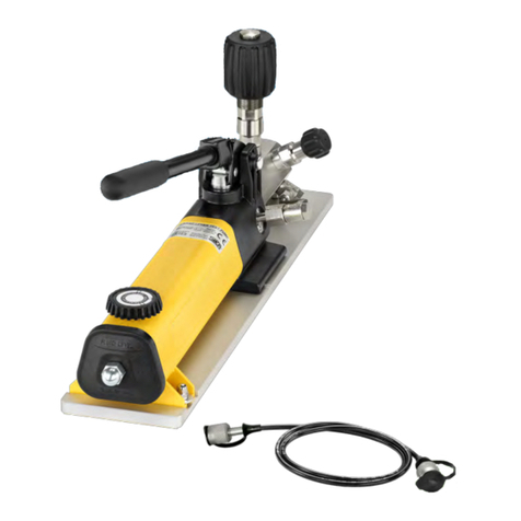
Pneumatic pressure pump P4
for low pressures up to 4 bar.

P4
© SIKA • Ba_P4 • 04/2014
Contents Page
0About this operating manual.......................................................................................19
1Device description .......................................................................................................20
1.1 Intended use..............................................................................................................21
1.2 Exclusion of liability ..................................................................................................21
2Safety instructions.......................................................................................................22
3Construction and function...........................................................................................23
4Commissioning............................................................................................................24
5Operation .....................................................................................................................24
5.1 Generating pressure .................................................................................................25
5.2 Generating negative pressure ..................................................................................26
5.3 Carrying out and ending measurements..................................................................27
6Problems .....................................................................................................................28
7Maintenance, cleaning, storage and transportation ..................................................29
8Disposal .......................................................................................................................30
9Technical data .............................................................................................................31
9.1 Accessories ...............................................................................................................31
Copyright notice:
The reproduction, distribution and utilization of this operating manual as well as the communication
of its contents to others without express authorization is prohibited. Offenders will be held liable for
the payment of damages. All rights reserved in the event of the grant of a patent, utility model or
design.

P4 About this operating manual
Technical changes reserved
0About this operating manual
The operating manual is aimed at specialists and semi-skilled personnel.
Before each step, read through the relevant advice carefully and keep to the specified
order.
Thoroughly read and understand the information in the section "Safety instructions".
If you have any problems or questions, please contact your supplier or contact us directly
at:
Dr. Siebert & Kühn GmbH & Co. KG
Struthweg 7-9 • D - 34260 Kaufungen
05605-803 0 • 05605-803 54
Hazard symbols and other symbols used:
+p
CAUTION! Risk of injury in the case of excessive pressure!
This sign indicates dangers which could arise from excessive pressure in a piece of equip-
ment.
CAUTION! Material damage!
This symbol indicates actions which could lead to possible damage to material or environ-
mental damage.
ADHERE TO OPERATING MANUAL! NOTICE!
This symbol indicates important notices,
tips or information.
Pay attention to and comply with informa-
tion that is marked with this symbol.
Follow the specified instructions and steps.
Adhere to the given order.
Check the specified points or notices.
Reference to another section, document or
source.
• Item

Device description P4
© SIKA • Ba_P4 • 04/2014
1Device description
The P4 pressure pump is used for checking, adjusting and calibrating all kinds of pressure
equipment.
It was specifically developed for low pressures up to 4
bar. It is also possible to generate negative pressure,
but this is very dependent on the test chamber volume.
The pressure pump can be used for test items directly
on location, thanks to its light weight and compact de-
sign.
When the pressure pump is used, it needs to be con-
nected to a reference gauge and to the test item (§ 3
"Function").
Scope of delivery and accessories:
Check the delivered items.
Pressure pump.
Pressure hose:
The pressure hose is supplied from the factory al-
ready screwed onto the pressure pump.
The pressure hose should remain attached to the
pressure pump during operation, storage and
transportation. Removing the pressure hose
should be avoided.
Operation manual.
Accessories (optional).
Transportation cases, adapter sets, seal sets and reference gauges can be ordered as acces-
sories.
Transportation case:
The transportation case provides optimal protec-
tion for the pressure pump and other accessories
with its tight-fitting rigid foam inlay.
A document compartment is located in the lid be-
hind the burl foam inlay.
Adapter set:
The adapter set comprises 11 adapters for all
common pressure connections with or without
pins.
Seal set:
The seal set contains flat seals made of plastic and O-rings for all common pressure
connections.
Quick snap connection set:
The quick snap connection set is available for the simple connection of
sensors with hose connections. It comprises a Y-plug connector, PA
hose and blanking plug.

P4 Device description
Technical changes reserved
Replacement pressure hose with seals:
The pressure hose is available separately as a replacement part with the necessary
seals.
SIKA reference gauge:
Various reference models from SIKA's product
range can be used.
1.1 Intended use
The P4 pressure pump may only be used for the generation of air pressure. Use with any
other media, particularly hydraulic oil, will result in damage to the pressure pump.
The pressure pump may not be attached to external pressure sources.
WARNING! No safety component!
The P4 pressure pump is not a safety component in accordance with Directive 2006-42-EC
(Machine Directive).
Never use the P4 as a safety component.
The delivered appliance is only guaranteed to operate safely if used for the intended purpose.
The specified limits (§ 9 "Technical data") may not be exceeded under any circumstances.
Before ordering and installation, check that the pressure pump is suitable for your needs.
1.2 Exclusion of liability
We accept no liability for any damage or malfunctions resulting from incorrect installation,
inappropriate use of the device or failure to follow the instructions in this operating manual.

Safety instructions P4
© SIKA • Ba_P4 • 04/2014
2Safety instructions
Before you install the P4, read through this operating manual carefully. If the instruc-
tions contained within it are not followed, in particular the safety guidelines, this could
result in danger for people, the environment, and the device and the system it is con-
nected to.
The P4 correspond to the state-of-the-art technology. This concerns the accuracy, the oper-
ating mode and the safe operation of the device.
In order to guarantee that the device operates safely, the operator must act competently and
be conscious of safety issues.
SIKA provides support for the use of its products either personally or via relevant literature.
The customer verifies that our product is fit for purpose based on our technical information.
With this verification all hazards and risks are transferred to our customers; our warranty is
not valid.
Qualified personnel:
The personnel who are charged for the installation and operation of the P4 must hold a
relevant qualification. This can be based on training or relevant tuition.
The personnel must be aware of this operating manual and have access to it at all times.
General safety instructions:
In all work, the existing national regulations for accident prevention and safety in the
workplace must be complied with. Any internal regulations of the operator must also be
complied with, even if these are not mentioned in this manual.
Never use the pressure pump together with an external pressure source. Do not attach
an external pressure generator to the pressure pump.
Do not remove any attached components (test item, pressure hose, reference gauge)
when the pressure pump is under pressure:
Open the pressure relief valve before removing any of the components.
Do not use Teflon tape to seal the pressure connections. Surplus Teflon tape can enter
the pressure pump and damage it.
Only use adapters and seals that are available as accessories.
Non-pressurised storage: Only store the pressure pump with the pressure relief valve
open. This ensures that no pressure can be built up by unintentional pumping move-
ments.
Avoid external force of all kinds towards the pressure pump and its operating elements.
Do not use the pressure pump if it is damaged or defective.
Special safety instructions:
Warnings that are specifically relevant to individual operating procedures or activities can be
found at the beginning of the relevant sections of this operating manual.

P4 Construction and function
Technical changes reserved
3Construction and function
Construction:
Pump grip.
Piston rod.
Lock-on button.
Pump body with hand grip.
Connector reference gauge.
Fine adjustment valve (hand wheel).
Pressure relief valve (rotary knob).
Pressure hose with cap screw (test item
connection).
Function:
The correct functioning of the P4 pressure pump requires the pressure-proof connection of a
reference and a test item . The test item respectively the pressure device to be tested
(hereafter referred to as 'test item') is connected to the cap screw of the pressure hose .
The upstream pressure in the measurement setup is
generated by the integrated piston pump + . The
number of pump movements depends on the required
test pressure and on the volume of the measurement
setup.
To perform tests at low pressure, a 100-percent seal-
ing of the test chamber is required. To accomplish
this, an additional valve – the test chamber valve – is
closed between the pump room and the test chamber
Set the pressure to the required value through the fine
adjustment valve .
The pressure can be correspondingly reduced or com-
pletely relieved with the pressure relief valve .
The generated pressure is displayed on the reference test gauge and compared with the
measurements of the test item .
Example measurement setup

Commissioning P4
© SIKA • Ba_P4 • 04/2014
4Commissioning
In order for the pressure pump to be operated, it is vital that its connections with the refer-
ence gauge and the test item are pressure-resistant. The pressure hose is supplied already
bolted on to the pressure pump and should not be removed.
CAUTION! Material damage!
The test item must have absolutely nothing adhering to it (oil, grease, water ...).
Impurities can be transported into the pressure pump via the pressure hose, causing
damage to the pump.
Maximum torque of the pressure connections!
Reference: 15 Nm
Test item: 15 Nm
Complete the following steps before using the pressure pump:
Screw the reference gauge tightly to the top of the pressure pump with the correct seal
(Connector reference gauge G ¼).
Clean the connection of the test item and ensure that no oil or other substances can en-
ter into the pressure hose.
Select the suitable adapters and seals for the test item's connection.
Join the adapters and seals to the test item and the cap screw of the pressure hose
(G ¼). Whilst doing this ensure that the O-ring is correctly positioned in the cap screw.
5Operation
CAUTION! Damage to valve stop!
If put under too much strain the stop and the pressure pump will be damaged.
Only continue to tighten the valves (the fine adjustment, pressure relief and switch
valves) by hand, once the stop has been reached.
Before using the device, check that
the reference gauge is connected to the pressure pump.
the test item is joined to the pressure hose.
all pressure connections are correctly in place, so that they resist pressure.

P4 Operation
Technical changes reserved
5.1 Generating pressure
CAUTION! Damage to test item!
Adhere to the maximum pressure of the test item!
Only create an admission pressure with the pump that is lesser than the necessary test-
ing pressure. Following this carefully increase the pressure using the fine adjustment
valve.
Preparation:
If necessary, switch on the reference manometer and the test item.
Close the pressure relief valve.
Turn the valve knob clockwise to the limit stop.
Place the integrated test chamber valve in the pump position.
To do that, turn the pump handle counter-clockwise to the limit stop.
Build up upstream pressure:
Hold the pressure pump tight with one hand on the handle and the other on the pump
grip.
Build up the upstream pressure through repeated pump movements.
The larger the volume of the test chamber, the more pump movements are needed.
Seal the test chamber (required at pressure < 1 bar):
Push in the piston rod on the pump grip until the limit stop.
Slightly press down the lock-on button on the handle.
IMPORTANT! If the piston rod is not in the correct position, the lock-on button cannot
latch in.
Now turn the pump grip clockwise up to the limit stop.
The test chamber valve is closed.
Setting the test pressure:
Use the fine adjustment valve to precisely set the required test pressure.
• Turn the hand wheel clockwise to increase the pressure.
• Turn the hand wheel counter-clockwise to reduce the pressure.
Turn the hand wheel accordingly to set the required test pressure.
FINE ADJUSTMENT VALVE
When it is not under pressure the fine adjustment valve
moves very freely. The wide hand wheel of the fine ad-
justment valve can be moved into the needed position
very easily using with the palm of the hand.

Operation P4
© SIKA • Ba_P4 • 04/2014
5.2 Generating negative pressure
The generated negative pressure depends greatly on the volume of the test chamber. The
smaller the test chamber volume, the smaller the negative pressure can become.
The maximum generated negative pressure is approximately -0.3 bar.
Preparation:
If necessary, switch on the reference manometer and the test item.
Turn the hand wheel of the fine adjustment valve counter clockwise up to the "Pump body
limit stop".
Seal the test chamber.
• To do this, press the pump grip to the limit stop in the pump body.
• Keep the lock-on button pressed down
• Turn the pump grip clockwise up to the limit stop.
Close the pressure relief valve.
To do this, turn the valve knob clockwise up to the limit stop.
Generating negative pressure:
Turn the fine adjustment valve hand wheel counter-clockwise in the direction of the
“Pressure relief valve limit stop” until the required negative pressure is attained.

P4 Operation
Technical changes reserved
5.3 Carrying out and ending measurements
For adjustments, calibrations or an inspection of accuracy, it is vital that the test item and the
reference have the same pressure or negative pressure.
The pressure or negative pressure needed for the test points is built up and adjusted with the
pressure pump (§ 5.1 + 5.2).
When carrying out measurements, also pay attention to external factors such as transient
times and ambient and environmental conditions. They can falsify the measurement results.
Carrying out the measurements:
The user specifies the necessary measurement processes.
Carry out the necessary tests and measurements.
Document your results.
Completing the measurements:
Once the measurements have been completed, the positive or negative pressure in the pres-
sure pump, the test item and in the pressure hose need to be brought into balance.
CAUTION! Risk of injury through excessive pressure!
Do not remove any connected components (test item, pressure hose, reference gauge) if
the pressure pump is under pressure.
Open the pressure relief valve before removing any of the components.
Releasing pressure or equalising negative pressure:
Turn the pressure relief valve knob 2-3 rotations in an anti-clockwise
direction and wait until there is no longer any positive or negative pres-
sure.
Remove the test item with adapters and seals from the pressure hose.
Put the pressure pump away along with any accessories which have been used.
(§ 7: "Maintenance, cleaning, storage and transportation")
REFERENCE GAUGE + PRESSURE HOSE
The common reference models fit into the gaps in the transportation case and do not
need to be removed. The pressure hose can also remain attached to the pressure pump.
It should generally never be removed.
+p

Problems P4
© SIKA • Ba_P4 • 04/2014
6Problems
CAUTION! Material damage!
The pressure pump cannot be repaired by the user. In case of a defect, the device must
be replaced or returned to the manufacturer for repair.
Never open up the pressure pump and / or perform any repairs yourself.
The following table details what problems you can solve yourself and how to solve them.
Problem Possible cause Remedy
Defective / incorrect seal. Check seal (size / material / wear).
Seal incorrectly positioned. Check positioning of seal.
Pressure cannot be built up
(generating negative pressure).
Pressure relief valve open.
Close pressure relief valve.
Check connections.Pressure or negative pressure
fades (unstable).
Leakage in the test item.
Check positionin
g
of seals.

P4 Maintenance, cleaning, storage and transportation
Technical changes reserved
7Maintenance, cleaning, storage and transportation
Maintenance:
No maintenance is required for the pressure pump and it cannot be repaired by the operator
either. In the case of a defect the appliance must be sent back to the manufacturer for repair.
Check the seals and O-rings for fractures and wear before use.
Replace defective or worn seals and O-rings.
Cleaning:
Clean the hand pressure pump with a dry or slightly damp lint-free cloth.
Do not use sharp objects or aggressive cleaning agents to clean the pump. Avoid contact with
fluid or aggressive media.
Storage and transportation:
For storage and transportation we recommend our transportation case, which is available as
an accessory.
The tight-fitting rigid foam inlay offers optimum protection for the pressure pump with pres-
sure hose and accessories. A reference gauge of a suitable size can be transported and
stored in the case without being removed.
Before storage, we recommend that you consider the following points:
Clean the pressure pump and the accessories.
Turn the fine adjustment valve in a clockwise direction until
the thread is no longer visible (illustration).
Open the pressure relief valve.
Turn the pump grip counter-clockwise up to the limit stop.
IMPORTANT! Do not store under pressure!
Only store the pressure pump with the pressure relief valve open. This ensures that no
pressure can be built up by unintentional pumping movements.

Disposal P4
© SIKA • Ba_P4 • 04/2014
8Disposal
CAUTION! Risk of injury!
Never remove the device from a measuring arrangement in operation.
Make sure that the measuring arrangement is shut down professionally.
Before disposal:
Prior to disposal, ensure that
the measuring arrangement is switched off and is in a safe and de-energised state.
the measuring arrangement is depressurised and has cooled down.
all mounted parts were removed from the pressure pump.
Disposal:
No household waste!
The pressure pump P4 consists of various different materials. It should not be disposed
of with household waste.
Take the P4 to your local recycling plant
or
send the P4 back to your supplier or to SIKA.

P4 Technical data
Technical changes reserved
9Technical data
Type P4
Pump with hose
Medium: Air
Pressure range:
-Positive pressure 4 bar
-Negative pressure -0,3 bar (depending on test item / Reference)
Connection:
-Reference G ¼ and Quick-Snap Y-plug connection with PA hose (2 x 1 m)
-Test item G ¼ with Quick-Coupling and pressure hose (1 m)
Dimensions: ~ 225 x ø50 mm
Weight: ~ 980 g
9.1 Accessories
Accessories
Adapter set: G ⅛, G ¼ , G ⅜, G ½
NPT ⅛'' , NPT ¼'' , NPT ½''
M12x1,5 , M20x1,5
G ⅛A , G ¼ A
Seal set: Flat seals made of plastic
and O-rings
Transportation case:
-Lid Burl foam with document compart-
ment
-Main compartment Tight-fitting rigid foam inlay
for pump and accessories
-Dimensions ~ 450 x 370 x 110 mm
-Weight with pump and
accessories
~ 4,2 kg
Quick-Snap connection
set:
Y-connector with
2 x 1m PA-hose (6/4 mm)
and blanking plugs
Pressure hose: Replacement pressure hose with
seals
Illustration (example):
Pressure pump with accessories

P4
© SIKA • Ba_P4 • 04/2014
Mechanische Messtechnik
Mechanical measuring instruments
Durchflussmesstechnik
Flow measuring instruments
Elektronische Mess- & Kalibriertechnik
Electronic measuring- & calibration instruments
Table of contents
Other SIKA Water Pump manuals
Popular Water Pump manuals by other brands

YANGTECH
YANGTECH SMP Series Operation manual

Becker
Becker VT 4.2 operating instructions

Wilo
Wilo DrainLift S Series Installation and operating instructions

Druck
Druck PV 210 instruction manual

Cosmo
Cosmo CSPGU25 Technical information for installation and operation

Campbell
Campbell PVS4100C Specifications

Wheeler-Rex
Wheeler-Rex 36454 operating instructions

Tuxhorn
Tuxhorn tubra-PGS 01 Assembly and operating instructions

Liberty Pumps
Liberty Pumps Omnivore RE Series installation manual

Calpeda
Calpeda MPSU Series operating instructions

ARVEN
ARVEN TIGER 70 1 operating instructions

Pentair
Pentair HYDROMATIC 118 Installation and service manual