Siklu MultiHaul TG User manual

MultiHaul™ TG
Wireless 60 GHz L2 SDN Mesh
for Multi-Gigabit Ethernet
Installation, Operation and Maintenance Manual
MHTG-I&O-01, Issue A03
February 2021

This document is proprietary and confidential. No part of this document may be disclosed in any manner to a third party without prior
written consent. © Siklu Communication Ltd 2021 All rights reserved.
2
Trademarks
Siklu, the Siklu logo, and MultiHaul™ are all trademarks of Siklu Communication Ltd. All other product names and
trademarks mentioned in this document are trademarks or registered trademarks of their respective companies.
Copyrights
Copyright © 2021 Siklu Communication Ltd. All rights reserved.
No part of this publication may be reproduced or distributed in any form or by any means, or stored in a database
or retrieval system, without the prior written consent of Siklu.
Disclaimers
The information contained in this document is subject to change without notice.
Siklu assumes no responsibility for any errors that may appear. Siklu makes no warranties, expressed or implied,
by operation of law or otherwise, relating to this document, the products or the computer software programs
described herein.
This document was originally written in English. Please refer to the English language version for a full and accurate
description of all products and services described herein.

This document is proprietary and confidential. No part of this document may be disclosed in any manner to a third party without prior
written consent. © Siklu Communication Ltd 2021 All rights reserved.
3
1. Introduction
Contents
1. Introduction ................................................................................................................................................................... 5
1.1 Scope ....................................................................................................................................................................... 5
1.2 Applicable Products and Releases........................................................................................................................... 5
1.3 Audience .................................................................................................................................................................. 5
1.4 Conventions ............................................................................................................................................................. 5
1.5 List of Abbreviations................................................................................................................................................. 6
2. Safety and Regulatory Notices ....................................................................................................................................... 7
2.1 General .................................................................................................................................................................... 7
2.2 FCC Regulatory Statements ...................................................................................................................................... 7
2.3 Canada Regulatory Statements ................................................................................................................................ 7
2.4 EU Regulatory Notes .............................................................................................................................................. 10
3. MultiHaul™ TG Overview ............................................................................................................................................. 11
4. Installing the MultiHaul™ TG Units ............................................................................................................................. 13
4.1 Preparing the Site .................................................................................................................................................. 13
4.1.1 Physical and Environmental Requirements .................................................................................................... 13
4.1.2 Cabling Requirements ..................................................................................................................................... 14
4.1.3 Node Orientation ............................................................................................................................................ 15
4.2 MultiHaul™ TG Package Contents.......................................................................................................................... 15
4.3 Unpacking the MultiHaul™ TG Units ..................................................................................................................... 15
4.4 Required Tools ....................................................................................................................................................... 15
4.5 Mounting and Aligning the MultiHaul™ TG Node on a Pole .................................................................................. 16
4.6 Mounting the MultiHaul™ TG Node on a Wall ...................................................................................................... 22
4.7 Mounting and Aligning the MultiHaul™ TG TU on a Pole or Wall .......................................................................... 23
4.8 Connecting Cables ................................................................................................................................................. 24
4.8.1 Connecting the Cables to the MultiHaul™ TG Node ....................................................................................... 24
4.8.2 Connecting the Cables to the MultiHaul™ TG TU ........................................................................................... 25
4.8.3 Weatherproofing the Cables ........................................................................................................................... 25
4.8.4 Grounding MultiHaul™ TG Units .................................................................................................................... 26
4.8.5 Installing Lightning Surge Protectors on Cables .............................................................................................. 27
4.8.6 Powering Units ................................................................................................................................................ 27
4.8.7 Connecting Other Network Cables .................................................................................................................. 27
4.9 Unit LEDs ................................................................................................................................................................ 28
4.10 Link Up Verification ............................................................................................................................................. 29
4.10.1 Node Checks ................................................................................................................................................. 29
4.10.2 TU Checks ...................................................................................................................................................... 29

This document is proprietary and confidential. No part of this document may be disclosed in any manner to a third party without prior
written consent. © Siklu Communication Ltd 2021 All rights reserved.
4
1. Introduction
4.10.3 Configuring the System ................................................................................................................................. 29
4.11 Resetting the Unit ................................................................................................................................................ 30
5.
Management Concepts............................................................................................................................................ 31
4.1 Connecting to the CLI............................................................................................................................................. 31
4.2 Configuring Management IPv4 Address \ Default Gateway ................................................................................. 32

This document is proprietary and confidential. No part of this document may be disclosed in any manner to a third party without prior
written consent. © Siklu Communication Ltd 2021 All rights reserved.
5
1. Introduction
1. Introduction
1.1 Scope
This document describes how to install, configure, operate and maintain the MultiHaul™ TG, Siklu’s Wireless
60 GHz L2 SDN Mesh for Multi-Gigabit Ethernet.
1.2 Applicable Products and Releases
•
MultiHaul™ TG Node N366
•
MultiHaul™ TG Terminal Unit (TU) T265
•
MultiHaul™ TG Software MH-TG-1.0
1.3 Audience
This document assumes a working knowledge of wireless connectivity platforms and their operating
environments.
This document is intended for use by persons involved in planning, installing, configuring, and using the
MultiHaul™ TG units.
1.4 Conventions
The following conventions are used in this document in order to make locating, reading, and using information
easier.
Warning: Warns you that if you do not proceed as instructed, personal injury or loss of
life could result.
Caution: Informs you that if you do not proceed as instructed, damage to or
destruction of equipment, loss of functionality, or a health hazard to personnel may
result.
Note: Informs you of an optional activity that may be performed at this stage.

This document is proprietary and confidential. No part of this document may be disclosed in any manner to a third party without prior
written consent. © Siklu Communication Ltd 2021 All rights reserved.
6
1. Introduction
1.5 List of Abbreviations
FOV Field Of View
NVRAM Non-Volatile Random Access Memory
PD Powered Device
PoE Power over Ethernet
PSE Power Sourcing Equipment
RAM Random Access Memory
SDN Software-Defined Networking
SFP Small Form-Factor Pluggable
UV Ultraviolet
SFF Small Form Factor
PtMP Point To MultiPoint
PHY Physical layer
MTU Maximum Transmission Unit
Abbreviation
Description
CDRH
Center for Devices and Radiological Health, a branch of the United States Food and Drug
Administration (FDA)
OTA Over The Air
PoP Point of Presence
SaaS Software as a Service
TU Terminal Unit

This document is proprietary and confidential. No part of this document may be disclosed in any manner to a third party without prior
written consent. © Siklu Communication Ltd 2021 All rights reserved.
7
2. Safety
and
Regulatory
Notices
2. Safety and Regulatory Notices
The following are mandatory notices for installation and operation of MultiHaul™ TG Wireless Backhaul System.
Indications appearing here are required by the designated government and regulatory agencies for purposes of
safety and compliance.
2.1 General
2.2 FCC Regulatory Statements
This equipment has been tested and found to comply with the limits for a Class B digital device, pursuant to Part
15 of the FCC Rules. These limits are designed to provide reasonable protection against harmful interference in a
residential installation. This equipment generates uses and can radiate radio frequency energy and, if not installed
and used in accordance with the instructions, may cause harmful interference to radio communications. However,
there is no guarantee that interference will not occur in any installation scenario. If this equipment does cause
harmful interference to radio or television reception, which can be determined by turning the equipment off and
on, the user is encouraged to try to correct the interference by one or more of the following measures:
•
Reorient or relocate the receiving antenna.
•
Increase the separation between the equipment and receiver.
•
Connect the equipment into an outlet on a circuit different from that to which the receiver is connected.
•
Consult the dealer or an experienced radio/TV technician for help.
2.3 Canada Regulatory Statements
This Class B digital apparatus complies with Canadian ICES-003.
Cet appareil numérique de la classe B est conforme à la norme NMB-003 du Canada.
This device complies with Innovation, Science and Economic Development Canada’s license-exempt RSS standard
(s). Operation is subject to two conditions: (1) This device may not cause harmful interference, and (2) this device
must accept any interference that may be received or that may cause undesired operation.
Le présent appareil est conforme aux CNR d’Innovation, Sciences et Développement économique Canada
applicables aux appareils radio exempts de licence. L'exploitation est autorisée aux deux conditions suivantes : (1)
l'appareil ne doit pas produire de brouillage, et (2) l'utilisateur de l'appareil doit accepter tout brouillage
radioélectrique subi, même si le brouillage est susceptible d'en compromettre le fonctionnement.
Verify that your installation matches local codes, including insertion of surge protectors when
PoE power is provided from an injector that not certified for outdoor lines.
Changes or modifications to this equipment not expressly approved by the party
responsible for compliance (Siklu Communication Ltd) could void the user's authority
to operate the equipment.
Do not install or operate the MultiHaul™ TG units in the presence of flammable gases or
fumes. Operating any electrical instrument in such an environment is a safety hazard.

2. Safety
and
Regulatory
Notices
This document is proprietary and confidential. No part of this document may be disclosed in any manner to a third party without prior
written consent. © Siklu Communication Ltd 2021 All rights reserved.
10
2.4 EU Regulatory Notes
This product meets the technical requirements of ECC REC 07-03 (7 June 2019), Table 3, bracket C2, with operation
at 60.48 GHz and 62.64 GHz and radiated transmitted power (EIRP) under 40 dBmi. In some EU countries outdoor
operation of this device is not permitted. If in doubt, please enquire with your Telecommunications Regulator.
Les unités extérieures et les antennes doivent être installées par des professionnels
expérimentés d'installation qui sont familiers avec les normes locales et les codes de
sécurité et, si applicable, sont agréées par les autorités gouvernementales. Ne pas le
faire peut annuler la garantie du produit et peut exposer l'utilisateur final ou le
fournisseur de services a des d'obligations juridiques et financières. Les revendeurs ou
distributeurs de ces équipements ne sont pas responsables des blessures, des
dommages ou violations des règlements liés à l'installation des unités extérieures ou
des antennes. L'installateur doit configurer le niveau de puissance de sortie des
antennes conformément aux réglementations nationales et au type d'antenne.
Outdoor units and antennas should be installed ONLY by experienced installation
professionals who are familiar with local building and safety codes and, wherever
applicable, are licensed by the appropriate government regulatory authorities. Failure
to do so may void the product warranty and may expose the end user or the service
provider to legal and financial liabilities. Siklu Communication Ltd and its resellers or
distributors are not liable for injury, damage or violation of regulations associated with
the installation of outdoor units or antennas.
Changes or modifications to this equipment not expressly approved by Siklu
Communication Ltd or the party responsible for compliance could void the user's
authority to operate the equipment.
This document is proprietary and confidential. No part of this document may be disclosed in any manner to a third party without prior
written consent. © Siklu Communication Ltd 2021 All rights reserved.
11
3.
MultiHaul™ TG Overview
3. MultiHaul™ TG Overview
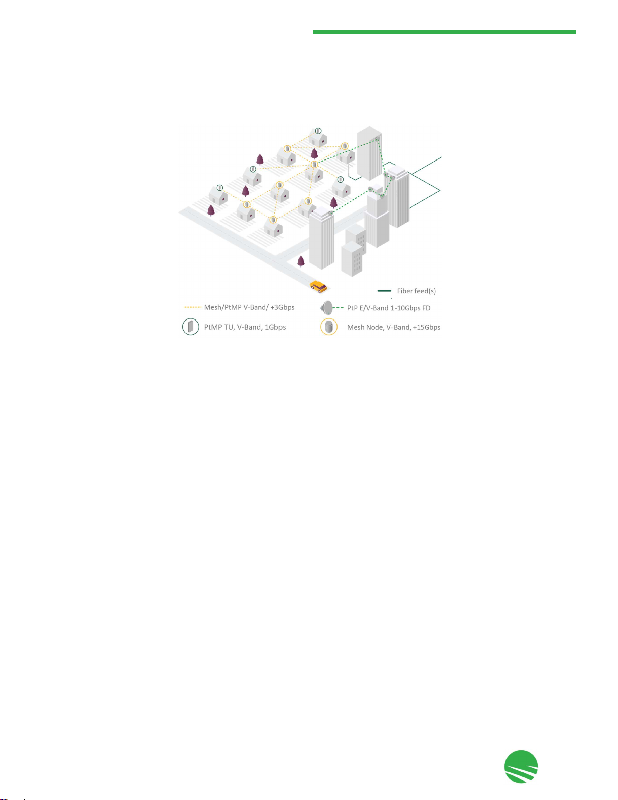
The MultiHaul™ TG family is an advanced solution for fixed wireless delivery of multi-Gigabit services to homes,
businesses and within smart cities Broadband IoT applications. It is complemented by additional Siklu solutions
for network design and operation, the SmartHaul™ suite of SaaS applications and services, together with
EtherHaul™, a series of very high capacity PtP wireless links.
MultiHaul™ TG is the culmination of innovation for L2 SDN mesh carrier-class systems operating in the
uncongested, unlicensed V-band, delivering very high capacity over small to large neighborhoods for a wide range
of applications. The plug and play units are designed for easy installation by a single technician, using a single cable
for power and data.
This section provides a brief overview of the MultiHaul™ TG units.
The MultiHaul™ TG family consists of the following units:
•
MultiHaul™ TG N366 - a compact multi-sector unit deployed as a L2 SDN mesh node with built-in self-backhaul.
Nodes can connect to additional N366 nodes to build a resilient wireless backbone across the served area, or to
a network POP via either a fiber connection or a Siklu EtherHaul™ link with up to 10 Gbps FD.
•
MultiHaul™ TG T265 - terminal units (TUs) deliver up to 1 GbE wirelessly to served locations. A smart beam-form-
ing antenna provides for easy installation of a high capacity reliable wireless link by a single person, and serves
one to three end-units per location.
N366 Node
Featuring 4 independent 90° sectors for a complete 360° coverage, a single node can be installed on a pole or roof
to serve multiple locations. The node supports up to 15 TUs in each 90° sector when the sector does not self-
backhaul to other nodes, up to a total of 60 TUs per N366. Each sector can also support 1 or 2 self-backhaul links,
reducing the number of TUs that can be supported to 13 or 14 respectively (each backhaul link comes at the
expense of a TU link).

This document is proprietary and confidential. No part of this document may be disclosed in any manner to a third party without prior
written consent. © Siklu Communication Ltd 2021 All rights reserved.
12
3. MultiHaul™ TG Overview
The main features of the node include:
•
4 x 90° sectors.
•
4600 Mbps aggregate capacity OTA (over the air) per sector.
•
3 ports:
•
RJ-45 port with PoE-In, and capable of speeds from 1 Gbps to 2.5, 5 and 10 Gbps.
•
RJ-45 port with PoE-Out, and capable of speeds up to 1 Gbps.
•
SFP+ socket for SMF or MMF connections at speeds of up to 1 Gbps or 10 Gbps, depending on the inserted
SFP device.
•
On-board web GUI or CLI, for local or remote management and operations.
•
Centralized management via SmartHaul™ EMS.
T265 TUs
Featuring 90° scanning for easy installation, long distance and high performance, a TU can be installed on a pole or
wall to serve between 1 - 3 connected devices with a copper or fiber interface. Additionally, the PSE/PoE-Out
feature simplifies installation of the served devices by removing the need for additional power equipment.
The main features of the TU include:
•
90° horizontal scanning.
•
4600 Mbps aggregate capacity OTA (over the air).
•
Up to 1 Gbps traffic.
•
Up to 3 Ports, model dependent:
•
RJ-45 ports with PoE-In, and capable of 2.5 and 1Gbps speeds.
•
Optional RJ-45 port with PoE-Out.
•
SFP+ socket for connection of SMF or MMF at speeds of up 10 Gbps.
•
On-board Web EMS or CLI, for local or remote management and operations.
•
Centralized management via SmartHaul™ EMS.
Additional information is provided in this manual, as well as in the N366 and T26x datasheets and product
descriptions.

This document is proprietary and confidential. No part of this document may be disclosed in any manner to a third party without prior
written consent. © Siklu Communication Ltd 2021 All rights reserved.
13
4. Installing the MultiHaul™ TG Units
4. Installing the MultiHaul™ TG Units
This section describes how to install the MultiHaul™ TG nodes and TUs.
4.1 Preparing the Site
Carefully select and prepare each site to make installation and configuration as simple and trouble-free as possible.
During site selection and preparation, take into account local safety regulations and consider the long-term needs
of both your network and your applications.
4.1.1 Physical and Environmental Requirements
Each site should meet the following requirements:
•
There must be a clear, unobstructed line-of-sight between the units.
•
MultiHaul™ TG units should be mounted on a fixed, stable, permanent structure. Units can be mounted using
the following methods:
•
On reinforced steel mounting poles with the following diameters:
• Node - 1.5" - 12"
• TU - 1.5" - 4"
•
Directly on a wall using the AX-MK-WM accessory, ordered separately from Siklu or your reseller.
Do not mount a MultiHaul™ TG unit on a structure that is temporary or easily
moved. Doing so may result in poor service or equipment damage.
Installation and maintenance of the MultiHaul™ TG link should only be done by service
personnel who are properly trained and certified to carry out such activities.
L'installation et l'entretien d’une unité MultiHaul™ TG ne doivent être effectués que par
du personnel de service qui sont formés et accrédités pour mener à bien ces activités.
Minimum safe distance from antenna while radiating is 29.75 cm / 11.7 in (general
public) or 13.3 cm / 5.2 in (occupational) (according to calculation done based on
"Environmental evaluation and exposure limit according to FCC CFR 47part 1, 1.1307,
1.1310; RSS-102, Safety Code 6).
Distance de sécurité minimum de l'antenne rayonnante est 29.75 cm (selon le calcul fait
sur la base de "l'évaluation environnementale et la limite d'exposition en accordance
avec FCC CFR 47 part 1, 1,1307, 1,1310, RSS-102, CODE 6 sécurité).
2" - 4" poles are recommended, in which case you can use the provided self-
locking bands.

This document is proprietary and confidential. No part of this document may be disclosed in any manner to a third party without prior
written consent. © Siklu Communication Ltd 2021 All rights reserved.
14
4. Installing the MultiHaul™ TG Units
4.1.2 Cabling Requirements
•
Install the MultiHaul™ TG unit where network connections and optional power cabling are ready for operation
and easily accessible.
•
All cabling connected to the MultiHaul™ TG unit should be outdoor grade, with UV protection.
•
Use the following cables as per your type of connection:
•
1 GbE - Cat5e (or higher) shielded outdoor cables terminated with metallic RJ45 connectors.
•
10 GbE - Cat6 (or higher) shielded outdoor cables terminated with metallic RJ45 connectors.
•
The MultiHaul™ TG unit is powered through the PoE input (ETH1). Take into account the power requirements of
the MultiHaul™ TG unit (see Section 3.2 - Technical Specifications and external PD(s) when planning Ethernet
cabling and passive POE Midspan/Injectors.
•
PSE Output (PoE Out) is available on MultiHaul™ TG units with more than a single Ethernet port.
•
PSE port output voltage is nearly the same as PoE port input voltage. The total cable length from the PoE
injector or PSE device to the last powered device (PD) should not exceed 100 meters (PSE to first unit + first unit
to second unit).
•
In order to protect indoor equipment, you must install surge protection circuits on all copper cables on their
entrance to the building.
•
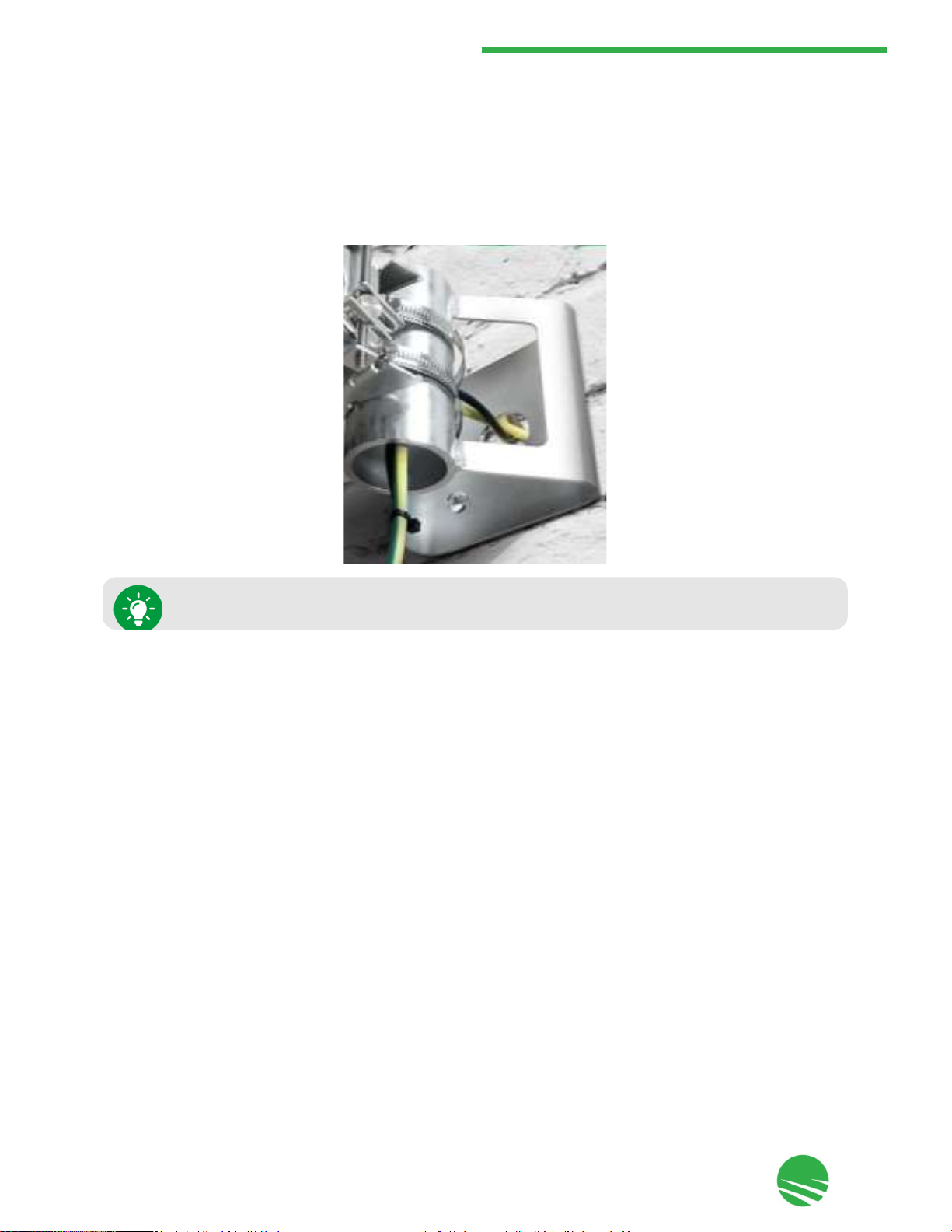
Install the MultiHaul™ TG unit in a location where proper electrical outdoor grounding is readily available.
Typically, the grounding connection is attached directly to the mounting pole. If not already present, then
suitable structure-to-earth grounding connections must be created before installation. Ground the unit using
16 AWG diameter (minimum) grounding cable or according to local electrical code.
•
PSE output is available only if the unit is powered directly by a power source
such as 48VDC, or a PoE Injector/Midspan.
•
One MultiHaul™ TG unit will power a 2nd unit, however that 2nd unit cannot
power a third unit.
•
You must also consider proper power-in limitations to avoid damage to the first
or second unit in the chain.
Improper electrical grounding can result in excessive electromagnetic interference or
electrical discharge.
Siklu will not be held responsible for any malfunction or damage if the unit is not
properly grounded.

This document is proprietary and confidential. No part of this document may be disclosed in any manner to a third party without prior
written consent. © Siklu Communication Ltd 2021 All rights reserved.
15
4. Installing the MultiHaul™ TG Units
4.1.3 Node Orientation
The network has been carefully designed by your or Siklu.'s Planning Team to achieve the highest standards in
availability and reliability, taking into account all potential lines of sight between the large quantity of units in your
network. It is critical to implement the orientation of the multi-sector nodes as they are designed by the planners
of the network. Sector 1 is the reference sector for node orientation. Make sure you obtain the azimuth for sector
1 from your or Siklu's Planning Team before installing, and align sector 1 along this planned azimuth, as described
in Section 4.5 - Mounting and Aligning the MultiHaul™ TG Node on a Pole, Step 7.
4.2 MultiHaul™ TG Package Contents
The MultiHaul™ TG N366 or T265 packages include the following components:
MultiHaul™ TG mounting bracket 1 1
4.3 Unpacking the MultiHaul™ TG Units
Before installation, the MultiHaul™ TG package content should be examined carefully that all parts listed in the
Quick Start Guide are present and there is no visible damage.
4.4 Required Tools
The following tools are required for MultiHaul™ TG installation:
•
Philips screwdriver, medium size head
•
7 mm hex socket driver
•
Standard open-end wrench, 13 mm for the port caps
•
Cutter
•
Cable ties (for securing network and optional power cables)
•
Cable labeling
Unpack the MultiHaul™ TG components with care to avoid damaging or scratching the
antenna radome.
Description N366
T265
MultiHaul™ TG unit
1
1
(attached to the TU)
Unit grounding cable (90 cm / 35.4 in)
1
1
All-weather shells
2
2
Self-locking bands
2
2
PoE
injector with AC cable
-
1

This document is proprietary and confidential. No part of this document may be disclosed in any manner to a third party without prior
written consent. © Siklu Communication Ltd 2021 All rights reserved.
16
4. Installing the MultiHaul™ TG Units
4.5
Mounting and Aligning the MultiHaul™ TG Node on a Pole
To mount the node on a pole:
1.
Insert self-locking bands
in the mounting bracket.
2.
Align the mounting bracket with the arrow pointing up and mount it on
the pole.
3.
If all four sectors have a clear field of view and are not blocked by the pole, tighten the self-locking bands.
The self-locking bands provided with the node are suitable for poles with a diameter
of 1.5"-4". Poles with a diameter of 2"-4" are recommended.
Do NOT tighten the self-locking bands yet.
This document is proprietary and confidential. No part of this document may be disclosed in any manner to a third party without prior
written consent. © Siklu Communication Ltd 2021 All rights reserved.
17
4. Installing the MultiHaul™ TG Units
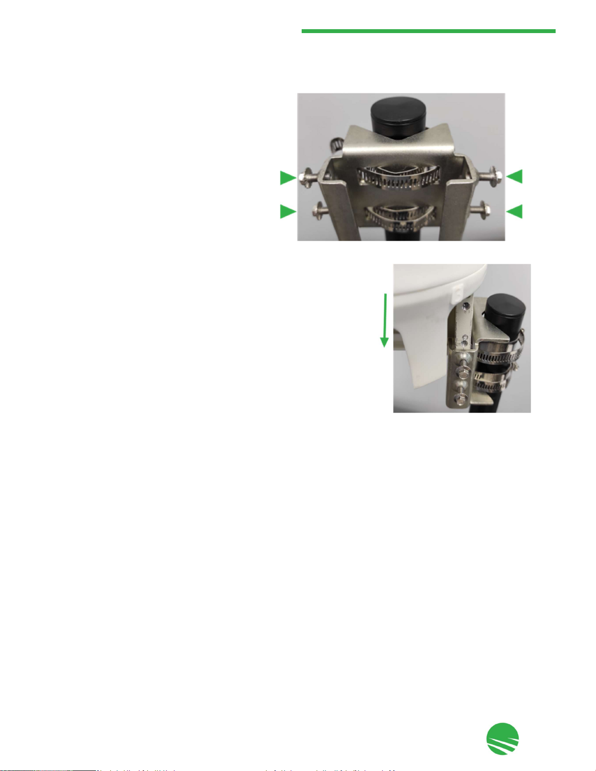
4.
Ensure that the 4 mounting bracket screws
are open.
5.
Slide the node into the mounting bracket.
This document is proprietary and confidential. No part of this document may be disclosed in any manner to a third party without prior
written consent. © Siklu Communication Ltd 2021 All rights reserved.
20
4. Installing the MultiHaul™ TG Units
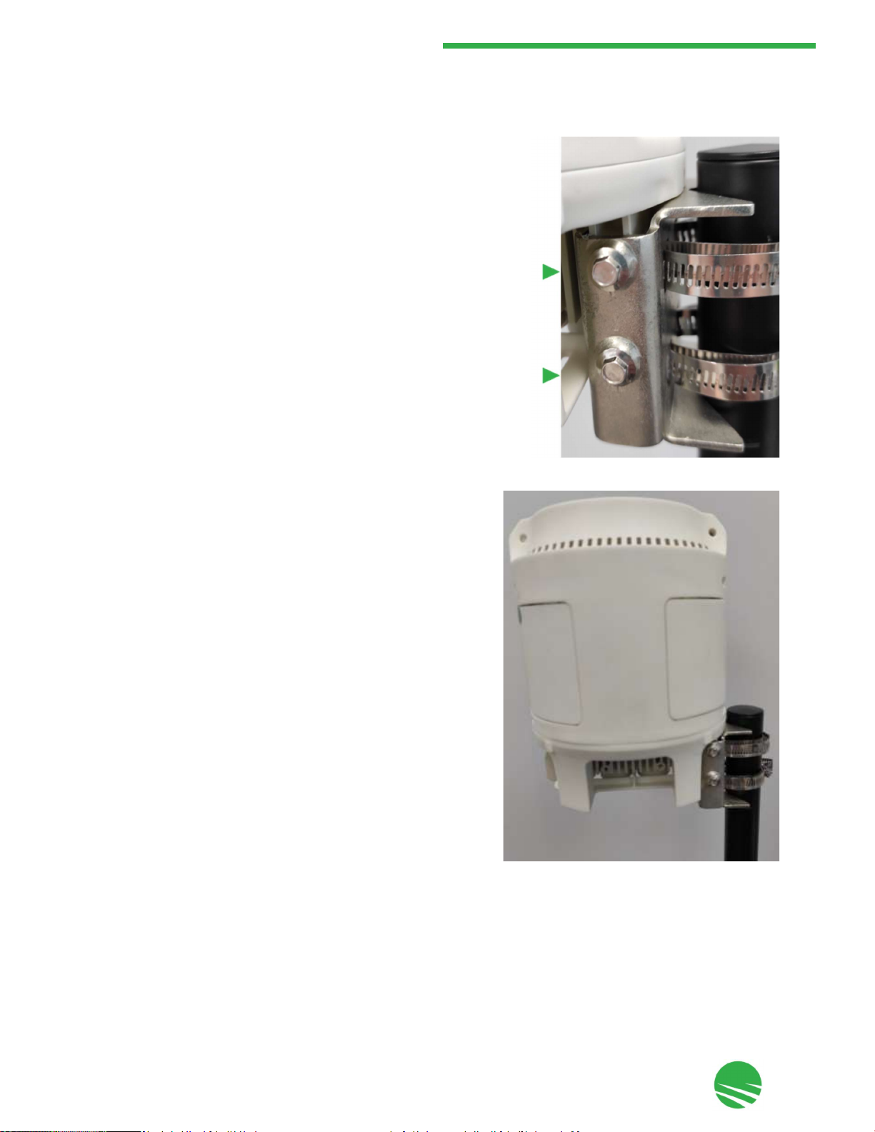
6.
Tighten the four mounting bracket screws so that the node is
securely fixed to the mounting bracket.
The node is now mounted on the pole.
This document is proprietary and confidential. No part of this document may be disclosed in any manner to a third party without prior
written consent. © Siklu Communication Ltd 2021 All rights reserved.
21
4. Installing the MultiHaul™ TG Units
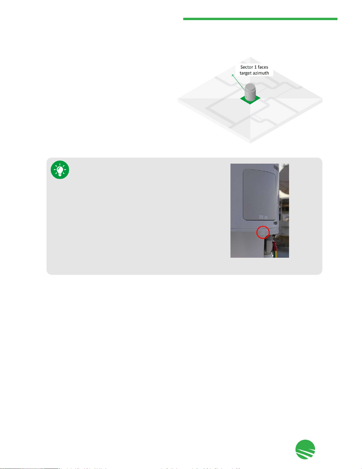
7.
Visually verify that the node's Sector 1 is aligned in
accordance to the network design and instructions
you received from your or Siklu's Planning Team
(see Section 4.1.3 - Node Orientation). If required,
slightly release the self-locking bands and optimize
the azimuth alignment by turning the mounting
bracket.
8.
Once sector 1 faces the target azimuth, tighten the self-locking bands if required to secure the bracket to the
mounting pole.
Each sector is identified by the number that appears below
the sector panel.
This document is proprietary and confidential. No part of this document may be disclosed in any manner to a third party without prior
written consent. © Siklu Communication Ltd 2021 All rights reserved.
22
4. Installing the MultiHaul™ TG Units
4.6 Mounting the MultiHaul™ TG Node on a Wall
The node can be mounted on a wall using the AX-MK-WM accessory and four wall-mount screws (not provided),
as shown in the following figure:
Order the AX-MK-WM accessory separately from Siklu or your reseller.

This document is proprietary and confidential. No part of this document may be disclosed in any manner to a third party without prior
written consent. © Siklu Communication Ltd 2021 All rights reserved.
23
4. Installing the MultiHaul™ TG Units
4.7 Mounting and Aligning the MultiHaul™ TG TU on a Pole or Wall
The TU is provided with a pre-attached mounting bracket suitable for mounting on a pole or wall.
Field of View Considerations while Mounting
When mounting the TU using the attached mounting bracket, the FOV (field-of-view) of the TU is as follows:
•
horizontal: ±45° electronically.
•
vertical : ±35° (25° electronically and 10° mechanical adjustment, achieved through the elevation lock bolts).
1.
Elevation lock bolts (2 x 7 mm on each side)
2.
All-weather shells (1 or 3, depending on model)
3.
Self-locking bands fixing points (for 2 x 130 mm bands
provided)
4.
Wall-mount fixing holes (4)
5.
Mounting bracket
TUs should be pointed towards the node.
This document is proprietary and confidential. No part of this document may be disclosed in any manner to a third party without prior
written consent. © Siklu Communication Ltd 2021 All rights reserved.
24
4. Installing the MultiHaul™ TG Units
4.8 Connecting Cables
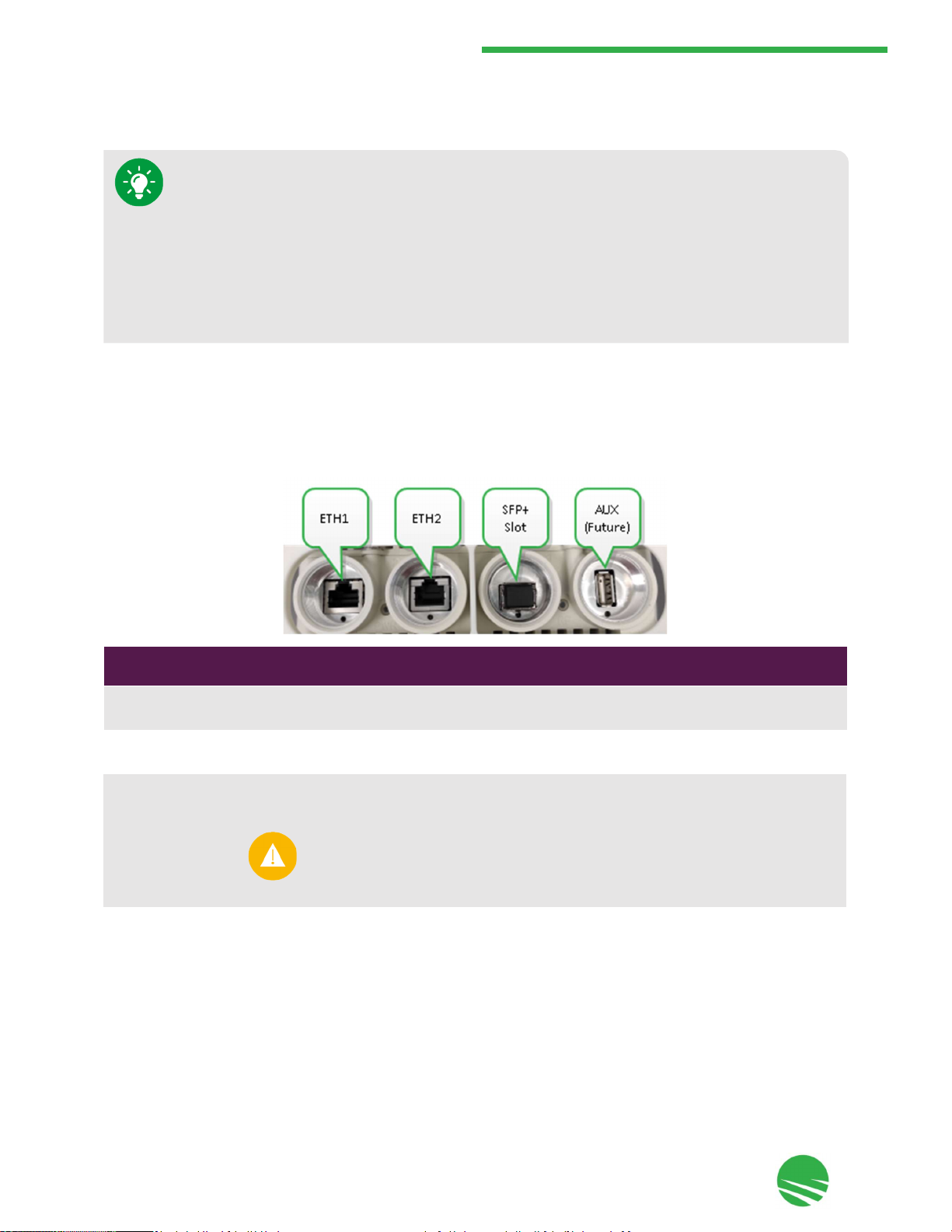
4.8.1 Connecting the Cables to the MultiHaul™ TG Node
The MultiHaul™ TG node includes the following ports on the connector panel under the node, as shown and
described below:
Port
Connector
Type Description
ETH1 RJ45 • 10 GbE (10/5/2.5/1 GbE)
•
PoE in
ETH2 RJ45 • 1 GbE
•
PoE out
AUX USB For future use
•
When mounting the TU on a pole: if additional vertical adjustment is required, use
the EH-MK-SM mounting kit.
•
When mounting the TU on a wall using the attached mounting bracket: if additional
horizontal adjustment is required, use the AX-MK-WM accessory.
•
When mounting the TU on a wall: if both additional horizontal and vertical
adjustment are required, use the EH-MK-SM mounting kit and the AX-MK-WM
accessory together.
ETH3
SFP+
•
1
GbE
•
10
GbE
Use only Class 1 Laser SFP/SFP+ with rated voltage of 3.3 Vdc which is safety
approved to UL/EN/IEC 60950-1, and is CDRH (Center for Devices and
Radiological Health) registered if deploying in the USA.
Table of contents
Other Siklu Network Hardware manuals


Popular Network Hardware manuals by other brands

Linksys
Linksys EFG80 - EtherFast Instant GigaDrive NAS... Specifications

UNICORECOMM
UNICORECOMM UM621N user manual

Systimax
Systimax AirSPEED AP541 user guide
 user guide")
HP
HP SL500 (M852x) user guide

DPS Telecom
DPS Telecom NetGuardian 216F user manual

Kindermann
Kindermann HDMI/USB-HDBT3 Extender 4K60 Set Commissioning and operating instructions


