Siko MSK210 User manual
MSK210+MB200/1+MR200 Datum 11.05.2015 Art.Nr. 81417 Änd. Stand 87/15 1
MSK210
MB200/1
MR200
DEUTSCH
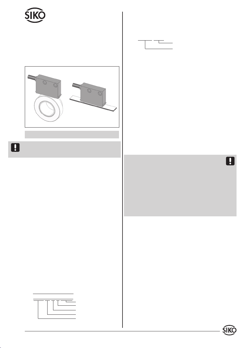
Sensordarstellungen sind exemplarisch und gül-
tig für alle Bauformen, sofern nicht gesondert be-
schrieben.
1. Gewährleistungshinweise
• LesenSievorderMontageundderInbetriebnahme
diesesDokumentsorgfältigdurch.BeachtenSiezu
IhrereigenenSicherheitundderBetriebssicherheit
alle Warnungen und Hinweise.
• Ihr Produkt hat unser Werk in geprüftem und
betriebsbereitem Zustand verlassen. Für den
BetriebgeltendieangegebenSpezifikationenund
die Angaben auf dem Typenschild als Bedingung.
• Garantieansprüche gelten nur für Produkte der
Firma SIKO GmbH. Bei dem Einsatz in Verbindung
mitFremdproduktenbestehtfürdasGesamtsystem
kein Garantieanspruch.
• Reparaturen dürfen nur im Werk vorgenommen
werden. Für weitere Fragen steht Ihnen die Firma
SIKO GmbH gerne zur Verfügung.
2. Identifikation
Magnetband: Das Magnetband ist durch eine fort-
laufende Bedruckung identifizierbar.
Benutzerinformation
MSK210 Magnetsensor
MB200/1 Magnetband
MR200 Magnetring
Magnetsensor, Magnetring: Das Typenschild zeigt
den Gerätetyp mit Variantennummer. Die Lieferpa-
piere ordnen jeder Variantennummer eine detail-
lierte Bestellbezeichnung zu.
z. B. MSK210-0023
Varianten-Nr.
Geräte-Typ
3. Mechanische Montage
Die Montage darf nur gemäß der angegebenen IP-
Schutzart vorgenommen werden. Das System muss
ggfs. zusätzlich gegen schädliche Umwelteinflüsse,
wie z. B. Spritzwasser, Lösungsmittel, Staub, Schlä-
ge, Vibrationen, starke Temperaturschwankungen
geschützt werden.
3.1 Montage Magnetband
Die Montage muss plan zur Montagefläche bzw. der
zu messenden Strecke erfolgen. Welligkeiten ver-
schlechtern immer die Messgenauigkeit.
Aus technischen Gründen muss bei der Länge
gegenüber der Messstrecke ein Zumaß von min.
57mm berücksichtigt werden.
Achtung! Um optimale Verklebungen zu erreichen
müssen alle antiadhäsiven Fremdsubstanzen (Öl,
Fett, Staub usw.) durch möglichst rückstandslos
verdunstende Reinigungsmittel entfernt werden.
Als Reinigungsmittel eignen sich u. a. Ketone (Ace-
ton) oder Alkohole, die u. a. von den Firmen Loctite
und 3M als Schnellreiniger angeboten werden. Die
Klebeflächen müssen trocken sein und es ist mit
höchstmöglichem Anpressdruck zu verkleben. Die
Verklebungstemperatur ist optimal zwischen 20°C
und 30°C in trockenen Räumen.
Tip! Bei Verklebung langer Bänder sollte die
Schutzfolie des Klebebandes über eine kurze Teil-
strecke abgezogen werden, um das Band zu fixie-
ren. Daraufhin erfolgt das Ausrichten des Bandes.
Nun kann über die restliche Länge die Schutzfolie,
unter gleichzeitigem Andruck des Bandes, seitlich
herausgezogen werden (als Hilfsmittel kann eine
Tapetenandrückwalze verwendet werden).
Montageschritte (Abb. 1)
• Befestigungsfläche (1) sorgfältig reinigen.
• Am Magnetband die Schutzfolie (2) des Klebe-
bandes (3) entfernen.
• Magnetband (4) aufkleben.
• Magnetbandoberfläche sorgfältig reinigen.
• Am Abdeckband (5) die Schutzfolie (6) des Klebe-
bandes entfernen.
Chargennummer
Referenzpunkt
Werksto-Trägerband
Genauigkeit
MB Typ
MBxxxx GEK WT RP NNNNNN

2 MSK210+MB200/1+MR200 Datum 11.05.2015 Art.Nr. 81417 Änd. Stand 87/15
Abb. 2 Abb. 3
Abb. 4 Abb. 5
Abb. 1: Montage Magnetband
Verfahrrichtung
Signal A vor B aktive Seite
Kabelabgangs-
richtung
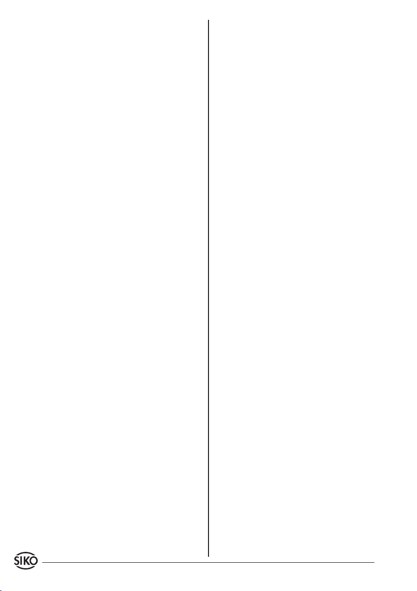
0.1 ... 1 mm
ohne Referenzpunkt
0.1 ... 0.4 mm
mit Referenzpunkt
Abstand Sensor/Magnetband
<1° <3°
Maximale Fluchtungsfehler
<1°
Referenzpunktlage zur Magnetbandbedruckung
Zul. Abweichung
Mitte Band/Sensor:
ohne Ref. ±2 mm
mit Ref. ±0.5 mm
MBxxxx GEK WT RP NNNNNN
• Abdeckband aufkleben (an beiden Enden leicht
überlappen lassen).
• DieüberlappendenEndendesAbdeckbandesgegen
Ablösen sichern.
• Der Magnetring MR200 muss möglichst kraft-
und spannungsfrei montiert werden. Eventuell
erforderliche Belastungen sind am Metallflansch
aufzubringen. Schläge auf den Magnetring sind
zu vermeiden.
• Ein Wellenfreistich entsprechend Abb. 6 wird
empfohlen
3.3 Montage Magnetsensor MSK210
Der Magnetsensor MSK210, Bauform A kann durch
Verwendung von 2 Schrauben M3 über die ø3.5mm
Durchgangslöcher befestigt werden. Es wird emp-
fohlen die beiliegenden Befestigungsschrauben
und Federringe zu verwenden (Anzugsmoment
0.25Nm).
• Kabel sind so zu verlegen, dass keine Beschädi-
gungsgefahr besteht. Zugentlastung und wenn
nötigSchleppketteoderSchutzschlauchvorsehen.
• Auf richtige Ausrichtung bezüglich der Zähl-
richtung achten (Abb. 6+7). Dies ist unerheblich
falls sich die Zählrichtung in der elektronischen
Auswertung umkehren lässt (wie z. B. bei den
Magnetbandanzeigen von SIKO).
Achtung! Die Toleranz- und Abstandsmaße müssen
über die gesamte Messstrecke eingehalten werden.
Anwendung LINEAR MSK210 mit MB200/1:
Achtung! Die Beeinflussung durch magnetische
Felder ist zu vermeiden. Insbesondere dürfen keine
Magnetfelder (z. B. Haftmagnete oder andere Dau-
ermagnete) in direkten Kontakt mit dem Magnet-
band geraten. In stromlosem Zustand werden Be-
wegungen oder Verstellungen des Magnetsensors
von der Folgeelektronik nicht erkannt und erfasst.
Montagebeispiele
Die einfache Montageart, durch angeschrägtes
Schutzband (Abb. 2), ist nur in sehr geschützter
Umgebung zu empfehlen. Bei ungeschützer Um-
gebung besteht Abschälgefahr. In solchen Fällen
sind Montagearten, wie in Abb. 3 und 4 gezeigt,
geeigneter.
Den optimalen Schutz bietet die Montage in einer
Nut (Abb. 5), die so tief sein sollte, dass das Ma-
gnetband vollständig darin eingebettet werden
kann.
3.2 Montage Magnetring MR200
Nach dem Aufschieben des Magnetringes auf die
Welle wird durch Anziehen des Gewindestiftes M6
der MR200 mit der Welle verbunden.
• Zwischen Welle und dem MR200 ist ein Schiebesitz
vorzusehen.

MSK210+MB200/1+MR200 Datum 11.05.2015 Art.Nr. 81417 Änd. Stand 87/15 3
Abb.7: Definition der Zählrichtung mit Magnetring
und Montage Sensor/Magnetring, Abstandsmaße,
Toleranzen
Freistich an
der Vollwelle
für Gewin-
destift wird
empfohlen
Kabelabgangsrichtung <3°
<1°
0.1 ... 0.8 mm ohne Referenzpunkt
0.1 ... 0.4 mm mit Referenzpunkt
Referenzpunkt
Signal
A vor B
Zul. Abweichung
Mitte Band/Sensor:
ohne Ref. ±2 mm
mit Ref. ±0.5 mm
Drehrichtung Magnetring
Abb. 6: Definition der Zählrichtung mit Magnetband
und Montage Sensor Magnetband, Abstandsmaße,
Toleranzen
Lage Ref.Punkt P=entspr. Lieferpapiere
Symbolische Dar-
stellung der Pole
Lage Ref.Punkt E=entspr. Lieferpapiere
min. 0.05 m
Referenzpunkt periodisch
Einmaliger Referenzpunkt
Abb. 8: Anschluss E1
so kurz wie
möglich
Schirm
4. Elektrischer Anschluss
• Verdrahtungsarbeiten dürfen nur spannungslos
erfolgen!
• Vor dem Einschalten sind alle Leitungsanschlüsse
und Steckverbindungen zu überprüfen.
Hinweise zur Störsicherheit
Alle Anschlüsse sind gegen äußere Störeinflüsse
geschützt. Der Einsatzort ist aber so zu wählen,
dass induktive oder kapazitive Störungen nicht
auf den Sensor oder dessen Anschlussleitung
einwirken können! Durch geeignete Kabelfüh-
rung und Verdrahtung können Störeinflüsse (z. B.
von Schaltnetzteilen, Motoren, getakteten Reglern
oder Schützen) vermindert werden.
Erforderliche Maßnahmen:
• Nur geschirmtes Kabel verwenden. Den Kabel-
schirm beidseitig auflegen. Litzenquerschnitt der
Leitungen min. 0.14 mm²; max. 0.5 mm².
• Die Verdrahtung von Abschirmung und Masse
(0V) muss sternförmig und großflächig erfolgen.
Der Anschluss der Abschirmung an den Potenti-
alausgleich muss großflächig (niederimpedant)
erfolgen.
• DasSystemmussinmöglichstgroßemAbstandvon
Leitungen eingebaut werden, die mit Störungen
belastet sind;ggfs. sind zusätzliche Maßnahmen
wie Schirmbleche oder metallisierte Gehäuse
vorzusehen. Leitungsführungen parallel zu Ener-
gieleitungen vermeiden.
• Schützspulen müssen mit Funkenlöschgliedern
beschaltet sein.
Spannungsversorgung
Die Spannungswerte sind abhängig von der Sen-
sorausführung und sind den Lieferpapieren sowie
dem Typenschild zu entnehmen.
z. B.: 24 VDC ±20%
Achtung! Die maximale Länge des Anschlusskabels
zwischen Sensor und Nachfolgeelektronik beach-
ten.
4.1 Anschlussarten / Anschlussbelegung
E1: Anschluss mit oenen Kabelenden.
Achtung! Verzinnte Litzen dürfen nicht in Verbin-
dung mit Schraubklemmverbindungen eingesetzt
werden.
Anwendung RADIAL MSK210 mit MR200:
1. Ummantelung entfernen.
2. Schirm auftrennen und verdrillen.
3. Litzen ca. 5 mm abisolieren und verdrillen.
4. Aderendhülsen aufquetschen.

4 MSK210+MB200/1+MR200 Datum 11.05.2015 Art.Nr. 81417 Änd. Stand 87/15
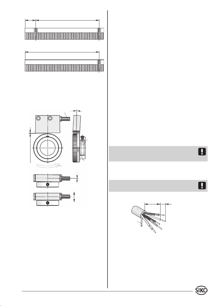
Abb. 9: Montage Anschlussart E6
Schirm
Schirm
Ansichtseite = Steckseite
Stiftkontakt
Ansichtseite = Steckseite
Stiftkontakt
Signal nicht invertiert invertiert
A PIN 3 PIN 1
B 4 2
+UB 2 4
GND 1 5
A/ - - - 6
B/ - - - 7
nc 5-7 3
Signal nicht invertiert mit
Referenzsignal
invertiert mit
Referenzsignal
A PIN 3 PIN 1
B 4 2
I, R 5 3
+UB 2 4
GND 1 5
A/ - - - 6
B/ - - - 7
I/, R/ - - - 8
nc 6, 7
E8: Anschluss mit 9-pol. D-SUB Stiftkontakt und
Buchsenkontakt.
Signal nicht invertiert invertiert
Arot rot
B orange orange
+UB braun braun
GND schwarz schwarz
A/ - - - gelb
B/ - - - grün
Signal nicht invertiert mit
Referenzsignal
invertiert mit
Referenzsignal
Arot rot
B orange orange
I, R blau blau
+UB braun braun
GND schwarz schwarz
A/ - - - gelb
B/ - - - grün
I/, R/ - - - violett
E6: Anschluss mit Kupplungsstecker und Kupp-
lungsdose. Steckermontage entsprechend Abb. 9.
1. Pos. 6 ... 10 über Kabelmantel schieben.
2. Kabel abisolieren.
3. Schirm umlegen.
4. Pos. 5 auf Litzen schieben.
5. Litzen an Pos. 3 löten (entspr. Anschlussplan).
6. Abstandhülse Pos. 4 aufweiten und über Litzen
stülpen, zusammendrücken und auf Pos. 3
stecken. Schlitz und Nut (Pos. 3 und 4) müssen
deckungsgleich sein.
7. Pos. 6 an Pos. 5 drücken, überstehen der Schirm
abschneiden.
8. Pos. 2 und 7 aufschieben und verschrauben.
9. Pos.8inPos.9stecken,beidesinPos.7schieben.
10.Pos. 10 mit Pos. 7 verschrauben.
Signal nicht invertiert invertiert
A PIN 3 PIN 1
B 4 2
+UB 2 4
GND 1 5
A/ - - - 6
B/ - - - 7
nc 5-9 3, 8, 9
11.Pos. 1 in Pos. 2 schieben.

MSK210+MB200/1+MR200 Datum 11.05.2015 Art.Nr. 81417 Änd. Stand 87/15 5
Signal nicht invertiert mit
Referenzsignal
invertiert mit
Referenzsignal
A PIN 3 PIN 1
B 4 2
I, R 5 3
+UB 2 4
GND 1 5
A/ - - - 6
B/ - - - 7
I/, R/ - - - 8
nc 6-9 9
5. Wartung
Die Oberfläche des Magnetbandes ist bei starker
Verschmutzung durch Staub, Späne, Feuchtigkeit
usw., von Zeit zu Zeit mit einem weichen Lappen zu
reinigen.
6. Fehlerbehandlung
Typische Fehler, die bei Anbau und Betrieb auftre-
ten:
• Das Magnetband wurde falsch montiert /aktive
Seite nach unten (siehe Kapitel 3.1).
• Zum Schutz des Magnetbandes wurde nicht das
mitgelieferteAbdeckbandverwendet.DasAbdeck-
band muss nicht magnetisierbar sein.
• DerSensoristnicht,odernichtkorrektangeschlos-
sen (Pinbelegung Kapitel 4.2).
• Die Abstandstoleranz zwischen Sensor und Ma-
gnetband/Magnetring wurde nicht eingehalten
(beim Band über die gesamte Messstrecke!), der
Sensor streift auf dem Magnetring (Abb. 6+7).
• Kabelunterbrechung / Abtrennung durch scharfe
Kanten / Quetschung.
• Der Sensor ist mit der aktiven Seite vom Band
abgewandt montiert (Abb. 6+7).
• Der Sensor wurde nicht entsprechend Abb. 6+7
ausgerichtet.
6 MSK210+MB200/1+MR200 Datum 11.05.2015 Art.Nr. 81417 Änd. Stand 87/15

MSK210+MB200/1+MR200 Datum 11.05.2015 Art.Nr. 81417 Änd. Stand 87/15 7
MSK210
MB200/1
MR200
ENGLISH
Exemplary sensor illustrations are valid for all sen-
sor types unless described separately.
1. Warranty information
• In order to carry out installation correctly, we
strongly recommend this document is read very
carefully. This will ensure your own safety and the
operating reliability of the device.
• Yourdevicehasbeenqualitycontrolled,testedand
is ready for use. Please observe all warnings and
information which are marked either directly on
the device or specified in this document.
• Warranty canonly beclaimed for componentssup-
pliedbySIKOGmbH.If the system is used together
with other products, there is no warranty for the
complete system.
• Repairs should be carried out only at our works.
If any information is missing or unclear, please
contact the SIKO sales sta.
2. Identification
Magnetic strip: identification by printing on the
strip.
User Information
MSK210 Magnetic sensor
MB200/1 Magnetic strip
MR200 Magnetic ring
Magnetic sensor, Magnetic ring: Please check the
particular type of unit and type number from the
identification plate. Type number and the corre-
sponding version are indicated in the delivery do-
cumentation.
e. g. MSK210-0023
version number
type of unit
3. Installation
For mounting, the degree of protection specified
must be observed. If necessary, protect the unit
against environmental influences such as sprayed
water, dust, knocks, extreme temperatures.
3.1 Mounting the magnetic strip
The mounting surface / measuring track must be
flat. Buckles or bumps will lead to measuring inac-
curacies.
For technical reasons the strip should be min.
57mm longer than the actual measuring distance.
Attention! To guarantee optimal adhesion oil,
grease dust etc. must be removed by using clean-
sing agents which evaporate without leaving resi-
dues. Suitable cleansing agents are e. g. ketones
(acetone) or alcohols; Messrs. Loctite and 3M can
both supply such cleansing liquid. Make sure that
the surface to be glued is dry and apply the strip
with maximum pressure. Glueing should preferably
be undertaken at temperatures between 20°C to
30°C and in dry atmosphere.
Advice! When applying long pieces of magnetic
strip do not immediately remove the complete
protective foil, but rather peel back a short part
from the end sucient to fix the strip. Now align
the strip. As the protective strip is then peeled back
and out press the tape firmly onto the mounting
surface. A wall paper roller wheel could be used to
assist in applying pressure onto the magnetic strip
when fixing it in position.
Mounting steps (Fig. 1)
• Clean mounting surface (1) carefully.
• Remove protective foil (2) from the adhesive side
of the magnetic strip (3).
• Stick down the magnetic strip (4).
• Clean surface of magnetic strip carefully.
• Remove protective foil (6) from adhesive tape on
the cover strip (5).
• Fixcoverstrip(bothendsshouldslightlyoverlap).
batch number
reference point
carrier strip
accuracy
MB type
MBxxxx GEK WT RP NNNNNN

8 MSK210+MB200/1+MR200 Datum 11.05.2015 Art.Nr. 81417 Änd. Stand 87/15
Fig. 1: Mounting of the magnetic strip
Fig. 2 Fig. 3
Fig. 4 Fig. 5
Travel direction
Signal A before B
active side
Direction of
outgoing cable
0.1 ... 1.0 mm
without reference point
0.1 ... 0.4 mm
with reference point
Gap sensor/magnetic strip
<1° <3°
Maximum alignment error
<1°
Position of the reference point relating
to the marking on the magnetic strip
Admissable deviation
middle of tape/sensor:
without ref. point ±2 mm
with ref. point ±0.5 mm
MBxxxx GEK WT RP NNNNNN
Attention! Do not expose the system to magnetic
fields. Any direct contact of the magnetic strip with
magnetic fields (e. g. adhesive magnets or other
permanent magnets) is to be avoided. Sensor mo-
vements during power loss are not captured by the
follower electronics.
Mounting examples
Mounting with chamfered ends (fig. 2) is not re-
commended unless the strip is installed in a safe
and protected place without environmental influ-
ences. In less protected mounting places the strip
may peel. There we recommend mounting accord.
to fig. 3 and 4.
Mounting in a groove (fig. 5) best protects the ma-
gnetic strip. The groove should be deep enough to
totally embed the magnetic strip.
3.3 Mounting of the magnetic sensor MSK210
The magnetic sensor MSK210, design A can be fa-
stened by using two bolts M3 over the ø3.5 mm
through holes. We recommend to use the enclosed
fixing screws and washer springs (fastening torque
0.25 Nm).
• Cables should be layed in such a way that there is
nodangerofdamaging.Provideten-sionreliefand
drag chain or casing, if necessary.
• Observe the correct alignment with regard to
the counting direction (fig. 6 and 7). This does
notapply if the counting direction can be reversed
in the electronic interpretation (e. g. in SIKO's
magnetic-strip displays).
Attention! The tolerance and gap measures must
be observed over the whole measuring length.
LINEAR application MSK210 with MB200/1:
3.2 Mounting of the magnetic ring MR200
Slide magnetic ring MR200 onto the shaft and then
tighten grub screw M6 to fix it to the shaft.
• Ensure sliding fit between shaft and MR320.
• Mount MR200 without force and without strain.
Possible forces should go to the metal flange.
Avoid knocks on the magnetic ring.
• Provide for a relief groove in the solid shaft (see
fig. 6).
• Also fix cover strip's ends to avoid unintentional
peeling.
MSK210+MB200/1+MR200 Datum 11.05.2015 Art.Nr. 81417 Änd. Stand 87/15 9
Fig. 7: Definition of the counting direction with ma-
gneticring and assemblagesensor/magneticring,gap
measure, tolerances
Undercut at
the solid shaft
for tread plug
is recommen-
ded
Direction of out-
going cable <3°
<1°
0.1 ... 0.8 mm without reference point
0.1 ... 0.4 mm with reference point
reference point
Signal
A before B
Admissable deviation
middle of tape/sensor:
without ref. point ±2 mm
with ref. point ±0.5 mm
Direction of rotation
of magnetic ring
Fig. 6: Definition of the counting direction with ma-
gnetic strip and assemblage sensor/magnetic ring,
gap measure, tolerances
Position of the reference point P = as
stated in the delivery documentation
Magnetic poles -
schema
Position of the reference point E = as stated
in the delivery documentation; min. 0.05 m
Periodical reference point
Unique reference point
Fig. 8: Connection type E1
as short as
possible
screening
4. Electrical connection
• Wiring must only be carried out with power o!
• Check all lines and connections before switching
on the equipment!
Interference and distortion
All connections are protected against the eects
of interference. The location should be selected
to ensure that no capacitive or inductive inter-
ferences can aect the sensor or the connection
lines! Suitable wiring layout and choice of cable
can minimise the eects of interference (e. g. in-
terference caused by SMPS, motors, cyclic controls
and contactors).
Necessary measures:
• Only screened cable should be used. Wire cross
section is to be at least 0.14 mm², max. 0.5 mm².
• Wiring to the screen and ground (0 V) must be se-
curedtoagoodpoint.Ensurethattheconnectionof
thescreenandearthismadetoalargesurfacearea
with a sound connection to minimise impedance.
• The system should be positioned well away from
cables with interference; if necessary a protective
screen or metal housing must be provided. The
running of wiring parallel to the mains supply
should be avoided.
• Contactor coils must be linked with spark sup-
pression.
Supply voltage
The voltages depend on the sensor designs; they
are to be taken from the delivery documentation
and the identification plate.
e. g.: 24 VDC ±20%
Attention! When connecting sensor and follower
electronics, please do not exceed the max. admis-
sable cable length.
4.1 Connection type / Pin outs
E1: Flying leads.
Attention! Tinned strands must not used in combi-
nation with screw/clamp connections.
RADIAL application MSK210 with MR200:
1. Remove cable coating.
2. Open screening and twist it.
3. Strip stranded wires to a length of 5 mm and
twist them.
4. Pinch stranded wires.
10 MSK210+MB200/1+MR200 Datum 11.05.2015 Art.Nr. 81417 Änd. Stand 87/15
Fig. 9: Mounting connection type E6
screening
screening
viewing side = plug-in side
plug pin
viewing side = plug-in side
plug pin
10.Screw parts 10 and 7 together.
11.Push part 1 into part 2.
Signal not inverted inverted
Ared red
B orange orange
+UB brown brown
GND black black
A/ - - - yellow
B/ - - - green
Signal not inverted with
reference signal
inverted with
reference signal
Ared red
B orange orange
I, R blue blue
+UB brown brown
GND black black
A/ - - - yellow
B/ - - - green
I/, R/ - - - violet
E6: Connection with plug pin and socket contact.
Plug mounting according to fig. 9.
1. Slip parts 6 to 10 over outer cable.
2. Strip cable.
3. Turn down screening.
4. Push part 5 onto ferrules.
5. Solder wires to part 3 (according connection
diagram).
6. Open spacer (part 4) and put it over ferrules,
squeeze and push it onto part 3. Slot and keyway
of parts 3 and 4 must align.
7. Press parts 6 and 5 together; cut prodruding
screening.
8. Push parts 2 and 7 together and screw.
9. Push part 8 into part 9 and slide both parts
into part 7.
Signal not inverted inverted
A PIN 3 PIN 1
B 4 2
+UB 2 4
GND 1 5
A/ - - - 6
B/ - - - 7
nc 5-7 3
Signal not inverted with
reference signal
inverted with
reference signal
A PIN 3 PIN 1
B 4 2
I, R 5 3
+UB 2 4
GND 1 5
A/ - - - 6
B/ - - - 7
I/, R/ - - - 8
nc 6, 7
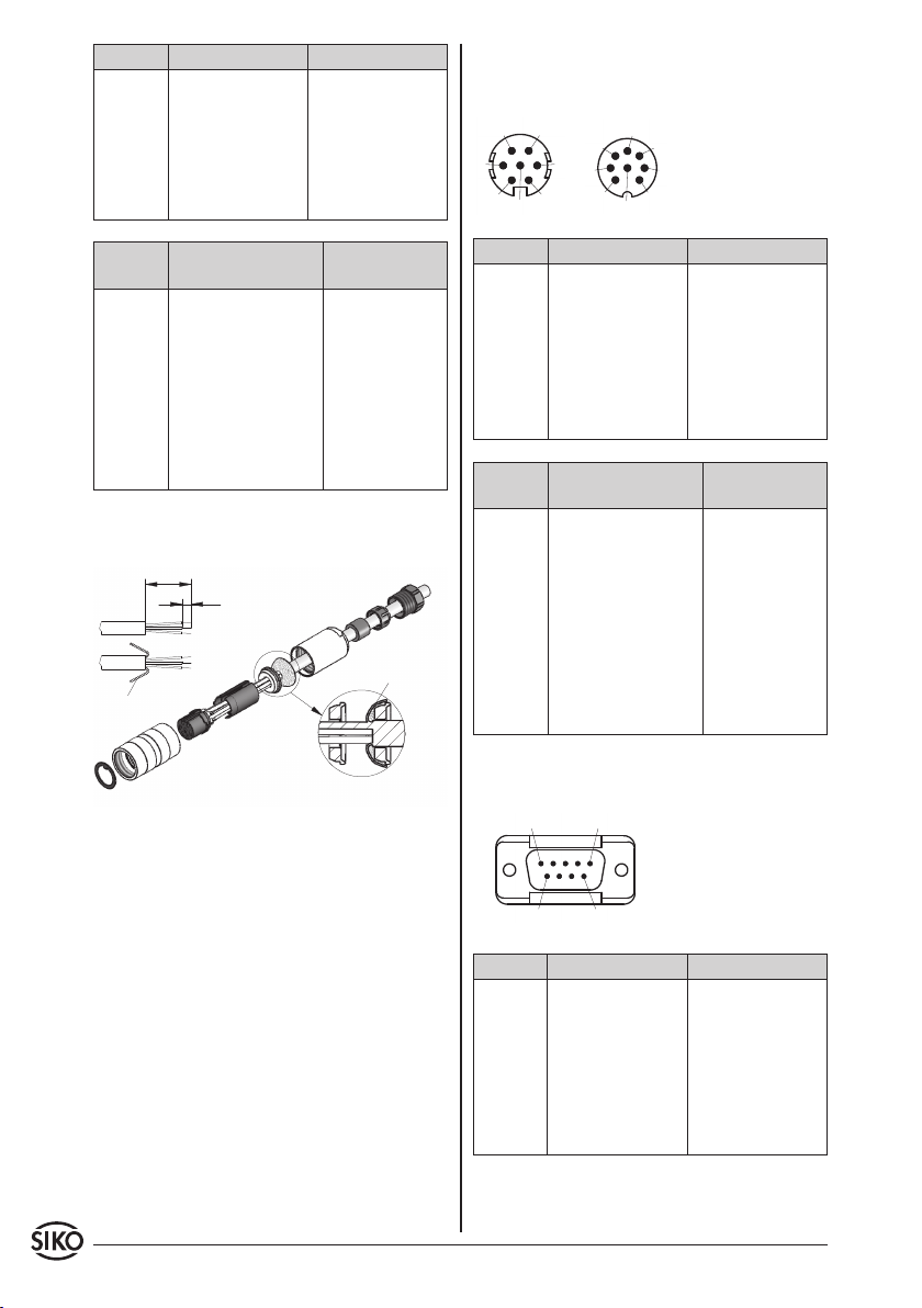
E8: Connection with 9 pole D-SUB plug pin and so-
cket contact.
Signal not inverted inverted
A PIN 3 PIN 1
B 4 2
+UB 2 4
GND 1 5
A/ - - - 6
B/ - - - 7
nc 5-9 3, 8, 9

MSK210+MB200/1+MR200 Datum 11.05.2015 Art.Nr. 81417 Änd. Stand 87/15 11
Signal not inverted with
reference signal
inverted with
reference signal
A PIN 3 PIN 1
B 4 2
I, R 5 3
+UB 2 4
GND 1 5
A/ - - - 6
B/ - - - 7
I/, R/ - - - 8
nc 6-9 9
5. Maintenance
We recommend cleaning the magnetic strip's sur-
face from time to time with a soft rag. This avoids
dirt (dust, chips, humidity ...) sticking to the strip.
6. Trouble shooting
Below are some typical errors which may occur duri-
ng installation and operation:
• Magnetic strip incorrectly mounted (active sur-
face must be mounted towards the sensor) (see
chapter 3.1).
• Use of foreign protective strip. Must always be
non-magnetic.
• Sensor not or incorrectly connected (pin connec-
tion, see chapter 4.2).
• Tolerance for the gap between magnetic sensor
and magnetic strip not observed over the total
traveldistance.Sensortouchesstrip(seefig.6+7).
• Cablesqueezed/ interrupted / cut by sharpedges.
• Sensor's active side not mounted towards the
magnetic strip (see fig. 6+7).
• Sensor has not been aligned according to fig. 6+7.

12 MSK210+MB200/1+MR200 Datum 11.05.2015 Art.Nr. 81417 Änd. Stand 87/15
SIKO GmbH
Werk/Factory:
Weihermattenweg 2
79256 Buchenbach-Unteribental
Postanschrift / Postal address:
Postfach 1106
79195 Kirchzarten
Telefon/Phone +49 7661 394-0
Telefax/Fax +49 7661 394-388
E-Mail info@siko.de
Internet www.siko-global.com
Service suppor[email protected]
Other manuals for MSK210
2
This manual suits for next models
2
Table of contents
Languages:


