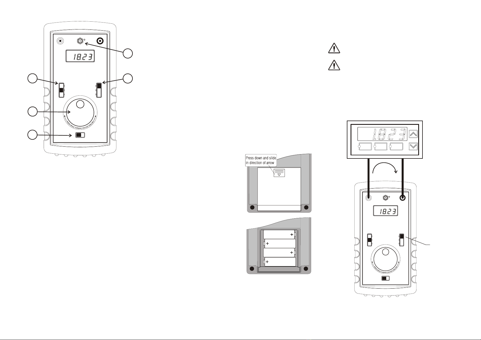
SIL CAL-2 User manual

mA Sink mode
In this mode the CAL-2 simulates a two wire transmitter. Use this
mode where the receiving instrument powers the current loop or
where the loop is powered by a separate power supply (as
shown below). The CAL-2 'sinks' (or regulates) the loop current to
the value set by the Output Level Selector / dial setting.
An external power supply of 12V to 30V DC is required.
For your personal safety and to avoid damage to the CAL-2, ensure
that the external circuit voltage is no greater than 30VDC before
connecting test leads.
Do not connect a power source directly across the CAL-2 output
terminals, the instrument will be damaged.
Please note: the CAL-2 displays a direct reading of the output
signal. With current output modes, in the event of an open circuit
loop, e.g. the instrument not connected or a loop fault exists, the
display will read '0.00'.
IO
+COM
Stroud Instruments Ltd www.sil.co.uk
SILCAL-2
mA / Volt Calibrator
Power
12V
DC
mA Source
Full-scale
Zero
Dial
Volts
C
mA Sink (2-wire
transmitter simulator)
+
+
_
+
_
Power
supply
30 V DC
max.
Switch the Output Mode
selector to 'mA Sink'
Volts mode
Use this mode for generating test signals in the range 0 to 10V.
Do not apply any external voltage to the output terminals in this mode,
this may result in damage to the CAL-2
For your personal safety, always ensure that the external circuit is
voltage free before connecting test leads.
STROUD INSTRUMENTS LTD,
36-40 Slad Road, Stroud Gloucestershire UK GL5 1QW
T. +44 (0) 1453 765433 F. +44 (0) 1453 764256
SIL
IO
+COM
Stroud Instruments Ltd www.sil.co.uk
SILCAL-2
mA / Volt Calibrator
Power
12V
DC
mA Source
Full-scale
Zero
Dial
Volts
C
mA Sink (2-wire
transmitter simulator)
+
+_
Switch the Output Mode
selector to 'Volts'
Doc ref UDCAL-2 Rev 1
WARNING!
It is important that this guide is read and fully
understood before attempting to use this
instrument. Instructions appearing in this
document, and current safety legislation,
must be observed to ensure personal safety
and to prevent damage to the instrument or
equipment connected to it.
Safety Information
The specifications for this instrument must not be exceeded. If the
instrument is used in a manner not specified, the protection provided
by the instrument may be compromised.
This instrument must not be used in explosive atmospheres, e.g.
explosive or flammable gas, dust or vapour.
This instrument contains no serviceable parts or user adjustments and
must not be dismantled. For servicing, repairs or recalibration the
instrument must be returned to the supplier.
Before connecting test leads to the external circuit, ensure the circuit
is voltage free for use in 'mA Source' and 'Volts' output modes and no
greater than 30VDC for 'mA Sink' output mode.
Product Specifications
Please refer to the product data sheet for full specifications. This
is available for download at www.sil.co.uk.
Receipt and unpacking
Please inspect the packaging and instrument thoroughly for any
signs of transit damage. If the instrument has been damaged,
please notify your supplier immediately.
mA / Volt Calibrator
Type CAL-2
User Guide
SIL

Basic operation
1. Power Switch - when switched on the CAL-2 performs
internal self-checking procedures. During this short period a
sequence of numbers are displayed.
2. Output Level Selector - provides for rapid selection
between three set-points: Full-scale (10V or 20mA) and Zero
( 0V or 0mA) fixed set-points, and the variable Dial setting.
NB for generating raised zero signals the Dial setting may be
used.
3. Dial - provides variable outputs across the output ranges
0 - 10.22V or 0 - 20.44mA (0.2% FSD ± 2 digits). To facilitate
rapid transition across the output range, dial speed is
increased 10-fold when the dial is pressed whilst turning.
The last dialled output value is retained in memory when the
CAL-2 is switched off. - this can be particularly useful for
storing a raised zero value. e.g. 4mA.
4. Output Mode Selector - selects between mA Source, mA
Sink and Voltage output.
5. External Power socket - for use with the optional universal
AC mains power supply (part no. CAL-2-PSU). When the jack
is inserted the battery supply is disconnected.
IO
+COM
Stroud Instruments Ltd www.sil.co.uk
SILCAL-2
mA / Volt Calibrator
Power
12V
DC
mA Source
Full-scale
Zero
Dial
Volts
C
mA Sink (2-wire
transmitter simulator)
+
1
3
2
5
4
Installing / replacing batteries
The CAL-2 mA / Volt Calibrator requires 4off Type AA (LR6,
MN1500, HP7) alkaline dry batteries. Replace the batteries when
the display indicates 'LOW BATTERY'.
To install batteries:
1. Turn off the power switch
2. Disconnect test leads
3. Remove the protective boot
4. Locate the battery
compartment cover on the
rear of the instrument, press
down as shown and slide off
the cover.
5. Note the polarity of the
batteries and fit as shown
(NB the polarity is embossed
on the floor of the
compartment).
6. Replace battery
compartment cover and
protective boot.
Mains power supply option
Only the optional universal mains power supply (part no.
3144-0012) should be used for this purpose. Switch off the
CAL-2 before connecting the power supply.
+
+
+
+
_
_
__
Examples
1. Voltage test signals required: 0V, 5V and 10V
Set Output Mode Selector to 'Volts'
Set Output Level Selector to 'Dial'
Adjust dial to set output to 5.00V
Use Output Level Selector to switch between full-scale (10V),
dial (5V) and zero.
2. mA test signals required: 4mA and 20mA
Set Output Mode Selector to 'mA Source' or 'mA Sink'
Set Output Level Selector to 'Dial'
Adjust dial to set output to 4.00mA
Use Output Level Selector to switch between full-scale
(20mA) and dial (4mA).
mA Source mode
In mA Source mode the CAL-2 provides the power source to
drive the current loop. Use this mode for passive (non-powered)
circuits (for powered current loops see mA Sink mode).
Do not apply any external voltage to the output terminals in this mode -
this may result in damage to the CAL-2
For your personal safety and to avoid damage to the CAL-2, always
ensure that the external circuit is voltage free before connecting test
leads.
Please note: the CAL-2 displays a direct reading of the output
signal. With current output modes, in the event of an open circuit
loop, e.g. the instrument not connected or a loop fault exists, the
display will read '0.00'.
IO
+COM
Stroud Instruments Ltd www.sil.co.uk
SILCAL-2
mA / Volt Calibrator
Power
12V
DC
mA Source
Full-scale
Zero
Dial
Volts
C
mA Sink (2-wire
transmitter simulator)
+
Alarm A
www.sil.co.uk
500-TT Process display
Alarm C
Alarm B
+_
Switch the Output Mode
selector to 'mA Source'
Table of contents
Other SIL Test Equipment manuals
Popular Test Equipment manuals by other brands

Chauvin Arnoux
Chauvin Arnoux C.A 757 user manual

ULTIMATE SPEED
ULTIMATE SPEED KH 4103 BATTERY AND ALTERNATOR TESTER manual

OfiTE
OfiTE 170-00-3 instruction manual

RenewAire
RenewAire PA ERV Series Installation, operation and maintenance manual

BACtrack
BACtrack View quick start guide

ATEQ
ATEQ Hydra Owner's/operator's manual