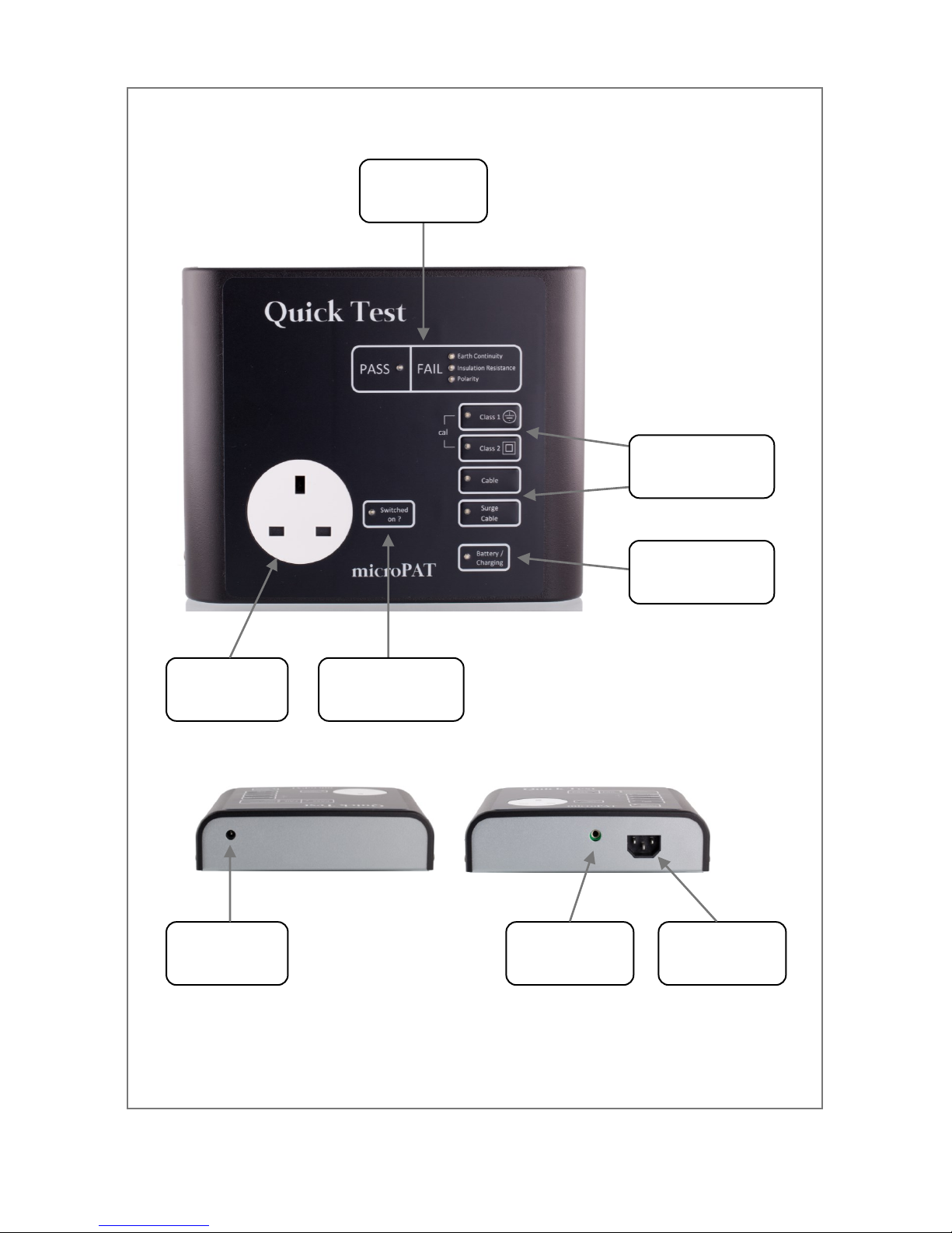
Quicktest microPAT User manual

microPAT
user manual

microPATCalibration
Your microPAT is calibrated for twelve months from the
date of purchase.
Have your microPAT re-calibrated with Quick Test any
time during the twelfth month and the calibration will be
valid for a full twelve months from the due date.
Contact calibration@quick-test.biz for details.
PAT Test Training
The Quick Test training team have successfully trained
thousands of people with all levels of experience.
We provide training in a professional and friendly
manner.
Contact training@quick-test.biz for details

1
Contents
Contents - - - 1
Introduction - - - 2
Features - - - 2
In-service Inspection & Testing 2
Overview - - - 3
Getting Started - - 4
Accessories - - - 4
Charging - - - 4
Battery Indication - - 4
Controls - - - 5
Results Display - - 5
Switched On Indicator - 5
Tests - - - - 6
Test Table - - - 6
Identifying Class 1 and Class 2 7
Testing a Class 1 Appliance 7
Testing a Class 2 Appliance 8
Testing an Extension Lead 9
Testing an IEC Lead - 10
User Cal Check - - 10
110V & 3-Phase Equipment 11
Specifications - - 12
Regulatory Information - 12
For your future reference please record your tester serial number:
Issue 1
MPAT -

2
Introduction
The microPAT Portable Appliance Tester provides the following features
in an attractive compact unit:-
Testing of Class 1 and Class 2 Appliances
Testing of IEC Leads
Testing of Extension Leads
It uses high tech electronics to ensure accurate and reliable operation
while being extremely simple and user friendly.
Features
In addition to carrying out the standard tests, the microPAT includes a
number of features:-
Additional 250V insulation test for surge protected extension leads
Tests different lengths of extension leads
Appliance 'switched on' check
User calibration check
In-service Inspection & Testing
Always carry out a full visual inspection of the appliance before
undertaking any tests. Although the microPAT is easy to operate, the HSE
recommend training to correctly carry out a regime of PAT testing.
Training with Quick Test will include guidance on what to look for when
carrying out a formal visual inspection, how to operate a PAT tester and
how often to carry out formal visual inspection and tests on appliances in
different environments.
Please contact Quick Test to arrange your training.

3
Overview
Charger
Connector
Results
Indicators
Test
Buttons
Battery/Charge
Indicator
IEC
Connector
Test Lead
Connector
Switched On
Indicator
Appliance
Socket

4
Getting Started
Accessories
The microPAT is supplied with the following accessories:-
Charger
Test Lead Set
Short IEC Lead ( used for testing extension leads )
Charging
The microPAT must only be charged with the supplied charger. It is
supplied partly charged but we suggest you charge your tester for at least
1 hour to boost the charge before using for the first time.
Your MicroPAT tester will perform in excess of 2000 tests per full battery
charge. It can also be used while plugged into the charger.
Battery Indicator
The Battery/Charging indicator will flash green for the
first hour when connected to the charger. This is a fast
charge period. After this the indicator will be a steady
green. To fully charge the microPAT it needs to be
charged for 24 hours. It is ok to leave it connected to
the charger.
If an incorrect charger is connected the indicator will flash red and green.
During testing if the battery is low, the indicator will flash red. When the
battery is too low for the microPAT to operate correctly the indicator will be
steady red and the test will stop.
WARNING
Under no circumstance must mains voltage be
connected to the microPAT

5
Controls
Results Display
Switched On Indicator
The microPAT is very simple to operate. The only controls
are four buttons used to select the required test.
To operate, simply press and release the appropriate test
button.
The indicator next to the test button will flash amber while
the test is being performed.
The test results are displayed for ten seconds after the test
is completed, the microPAT then shuts down.
When the test is complete the results appear on the results display.
If all the required tests pass, the green PASS indicator will light up.
If any of the required tests are a fail, the corresponding red FAIL indicator
will light up.
Additionally the indicator next to the test button will be green or red.
A new test can be started as soon as the results are being displayed,
there is no need to wait until the microPAT has shut down.
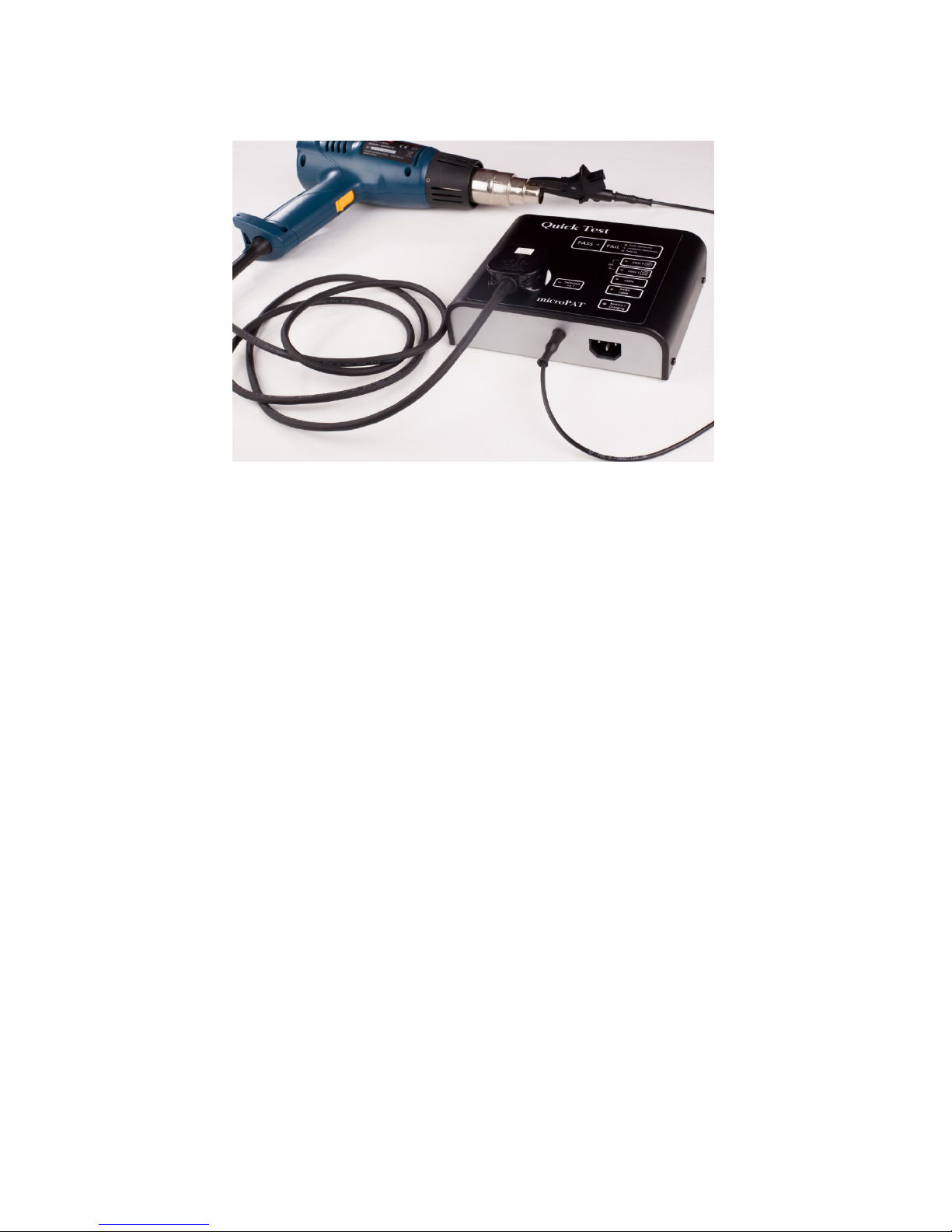
Any appliance switch must be in the ‘on’ position during
testing.
When testing Class 1 or Class 2, the microPAT will attempt
to determine if the appliance is switched on.
If it is unable to detect the appliance is switched on, the
‘Switched on ?’ indicator will flash red. If the appliance is
then switched on within five seconds the test will continue.
However because of the design of some appliances it is not
always possible for the tester to determine if it is switched
on. In this case pressing the corresponding test button will
continue the test immediately.

6
Tests
The microPAT carries out three different types of test. The actual tests
carried out depend on the equipment connected to the tester.
Earth Continuity
The earth continuity test measures the electrical resistance from the earth
pin of the mains plug to an earthed point on the appliance. This has to
have a very low electrical resistance to provide safe earth protection.
Insulation Resistance
The insulation resistance applies a high voltage ( 500V ) to the live and
neutral connections. This is then used to measure the electrical resistance
of the appliance to earth, or any exposed metal part.
This resistance has to be very high to protect the user.
Insulation Resistance - Surge Protected Extension Leads
The microPAT features an option to perform this test at 250V, this avoids
false fail indications when testing surge suppressed extension leads.
Polarity
This is used for extension leads and IEC leads. It checks that there is
correct connection between the live and neutral conductors through the
lead.
Test Table
Test Selected Earth Continuity Insulation
Resistance Polarity
Class 1 Y500V N
Class 2 N500V N
Cable Y500V Y
Cable Surge Y250V Y

7
Identifying Class 1 and Class 2
Testing a Class 1 appliance
1. Plug the test lead into the tester
2. Plug your class 1 appliance into the socket on top of the tester
3. Connect the crocodile clip or probe to some exposed metal on the
appliance
4. Press the Class 1 button
If the appliance is not switched on, the ‘ Switched on? ’ indicator will flash
to prompt you to do so. If the appliance is then switched on the tester will
proceed with the test. If it is not possible to switch the appliance on, press
the Class 1 button again to proceed with the test. The Class 1 test button
will flash amber while the test is underway.
When the test is finished, either the green PASS indicator will light up, or
the appropriate red FAIL indicators will light up. The Class 1 button will
also be green or red.
If the Class 1 appliance has no accessible metal part (including fixing
screws), then test as Class 2.
Class 1 appliances use an earth connection as a means
of protection.
Class 2 appliances do not use an earth connection. They
are frequently referred to as ‘double insulated’.
Class 2 appliances display the ‘double box’ symbol. Class 2 Symbol

8
Testing a Class 2 appliance
1. Plug the test lead into the tester
2. Plug your class 2 appliance into the socket on top of the tester
3. Connect the crocodile clip or probe to any exposed metal on the
appliance
4. Press the Class 2 button
If the appliance is not switched on, the ‘ Switched on? ’ indicator will flash
to prompt you to do so. If the appliance is then switched on the tester will
proceed with the test. If it is not possible to switch the appliance on, press
the Class 2 button again to proceed with the test. The Class 2 test button
will flash amber while the test is underway.
When the test is finished, either the green PASS indicator will light up, or
the appropriate red FAIL indicators will light up. The Class 2 button will
also be green or red.

9
Testing an Extension Lead
1. Plug the extension lead into the socket on top of the tester
2. Plug the IEC end of the short IEC lead into the IEC socket on the
front of the microPAT
3. Plug the 13A plug end of the short IEC lead into the first socket of
the extension lead
4. Press the Cable button, or Surge Cable button if the extension lead
is surge protected
The Cable or Surge Cable test button will flash amber while the test is
underway.
When the test is finished, either the green PASS indicator will light up, or
the appropriate red FAIL indicators will light up. The test button will also be
green or red.
The test must be repeated for ALL sockets on the extension lead.
If the extension lead has an earth connection, but the reading is high
because the lead is exceptionally long, the green PASS indicator will light
up, however the Earth Continuity FAIL indicator will flash amber. In this
case the extension lead should only be used in exceptional circumstances
where the risks are clearly understood.

10
Testing an IEC Lead
An IEC ( kettle ) lead is tested in exactly the same way as an extension
lead.
1. Plug the 13A plug end of the IEC lead into the socket on top of the
tester
2. Plug the IEC end of the IEC lead into the IEC socket on the front of
the microPAT
3. Press the Cable button
The Cable test button will flash amber while the test is underway.
When the test is finished, either the green PASS indicator will light up, or
the appropriate red FAIL indicators will light up. The test button will also be
green or red.
User Cal Check
In order to ensure that PAT testing equipment operates correctly, the IEE
Code of Practice for In-service Inspection & Testing of Electrical
Equipment states that ‘The accuracy of a test instrument should be
verified and recorded annually or in accordance with the manufacturer’s
instructions.’ The microPAT should be formally calibrated annually. Please
contact Quick Test to arrange calibration.
While formal calibration is required on an annual basis, the IEE
recommend that PAT testing equipment is checked on a regular basis to
confirm correct operation.
The microPAT incorporates a unique feature to perform this.
1. Plug the 13A plug end of the short IEC lead into the socket on top of
the tester
2. Plug the IEC end of the short IEC lead into the IEC socket on the
front of the microPAT
3. Press both the Class 1 and Class 2 buttons simultaneously
The Class 1 and Class 2 buttons will both flash amber and all three FAIL
indicators will flash red, but will turn off as each test passes. If the Cal
check passes the green PASS indicator will light up as well as the Class 1
and Class 2 buttons.

11
110V and 3-Phase Equipment
110V and 3-Phase equipment is tested in exactly the same way as any
other equipment.
The only additional requirement is the use of appropriate adapters to
connect to the microPAT.
Please contact Quick Test for details.

Specifications
Earth Continuity Test
Current Approx 120mA
OC Voltage 5V
Tolerance 5% +/- 10mΩ
Limits:
Class 1 <=200mΩ
Normal Ext <=300mΩ
Long Ext <=640mΩ
Insulation Resistance Test
Test Voltage 500V / 250V
SC Current 1mA
Tolerance 5%
Limits:
Class 1 & Cable >=2MΩ
Class 2 >=4MΩ
Supply
Voltage 12V +/-5%
Current 400mA max
Regulatory Information
LVD EN 61010
EMC EN 55011
12
The microPAT is produced by a registered WEEE producer:
Registration number WEE/HB3434XT.
This product should not be disposed of with household waste, it should
be handed over to an authorised collection site for recycling waste
electrical & electronic equipment.

Need Labels?
Accessories?
Quick Test can supply tested labels, adapters, and
spares for your microPAT.
Contact sales@quick-test.biz
Warranty Information
Quick Test warrants your microPAT against defects in
materials and workmanship for a period of one year from
the date of purchase.
This warranty covers only those defects which arise as a
result of normal use of the product, and does not apply
to improper use, modification, or maintenance.
This warranty does not affect your statutory rights.

www.quick-test.biz
Table of contents
Other Quicktest Test Equipment manuals
Popular Test Equipment manuals by other brands

Crowcon
Crowcon I-Test User's operation manual

HP
HP HP 85062A Operating and service manual

Polar Instruments
Polar Instruments T1500A Service manual

Burg Wächter
Burg Wächter SANTEC 513001 Quick installation guide

Siemens
Siemens Milltronics MWL Weight Lifter operating instructions

Saluki
Saluki DSO2000 user manual