Top Tronic T1105 User manual

ANALOGUE
EARTH RESISTANCE TESTER
T1105
INSTRUCTION MANUAL
ACV
6
8
10
12
4
2
0
0
5
10
15
20
25
30
Ω
BATT
GOOD
E P C
EARTH
VOLTAGE
BATT
CHECK
MAX.AC30V
CAT. IV 30V
Ω
X100
X10
X1
ALWAYS ENSURE CIRCUIT
TO TEST IS FREE OF VOLTAGE
BEFORE PROCEEDING
T1105
EARTH RESISTANCE TESTER
LOCK
PRESS TO TEST

INDEX
INTRODUCTION................................
SAFETY NOTES................................
FEATURES........................................
SPECIFICATIONS.............................
LAYOUT..............................................
MEASURING METHODS...................
MAINTENANCE..................................
PAGE
1
2
3
4
5
6-9
10-11

-1-
1. INTRODUCTION
NOTE
This meter has been designed and tested according
to CE. IEC / EN 61010-1, EN 61326-1 and other
safety standards. Follow all warnings to ensure safe
operation.
● Application:
Earth Resistance Tester is used to measure the
ohms (Ω) of an earth grounding installation for
buildings (residential, ofce, labs, hospitals),
computer server rooms, military installations,
cellular sites, radio and cable towers, etc.
It is used to determine if the earth (or ground)
is a good conductor of electricity.
● Purpose of Earth Grounding:
(1) Avoid human and animal electrical shock.
(2) Avoid unnecessary property and equipment
damage.
(3) Prevent re or explosion.
(4) Integrate electrical signal to attain proper
operation or measuring purpose.
(5) Provide a means of dissipation for power surges
caused by lightning strikes, static charges,
and other types of electrical interference.

-2-
2. SAFETY NOTES
● Read the following safety information carefully
before attempting to operate or service the meter.
● Use the meter only as specied in this manual,
otherwise the protection provided by the meter may
be impaired.
● Rated environmental conditions:
(1) Indoor and outdoor use.
(2) Installation Category IV 30V.
(3) Pollution Degree 2.
(4) Altitude up to 2000 Meter.
(5) Relative Humidity 80% Max.
(6) Ambient Temperature 0℃~40℃.
● Observe the International Electrical Symbols listed
below:
Meter is protected throughout by double
insulation or reinforced insulation.
Warning ! Risk of electric shock.
Caution ! Refer to this manual before using the
Meter.

-3-
3. FEATURES
● Capable of measuring earth voltage.
● 2mA measuring current permits the testing of earth
resistance without tripping earth leakage current
breakers in the circuit under test.
● In addition to facilitating for precision measurement,
test leads for simplied two-wire measuring system
also are supplied as standard accessories.
● Battery operated.
● Battery life indicator.
● Designed to meet IEC / EN 61010-1 EN 61326-1
safety standard.
● Calibration performed with supplied test leads.

-4-
4. SPECIFICATIONS
Measuring
Ranges
Earth Resistance
0-12Ω/0-120Ω/0-1200Ω
Earth Voltage
0-30V ac (40-500Hz)
Accuracy
Earth Resistance
±3% of full scale
Earth Voltage
±2.5% of full scale
Measuring
System
Earth resistance by constant
current inverter
(Square Signal) 820Hz
approx. 2mA
Power Source 1.5V (AA) x 8 or equivalent
Dimensions 175(L) x 85(W) x 75(D)mm
Weight Approx. 600g (battery included)
Accessories
Test leads (AL-36:red-15m,
yellow-10m,green-5m)
Simplied measurement probe.
(AL-33)
Auxiliary earth spikes.
Shoulder belt.
Instruction manual.
Batteries.
-5-
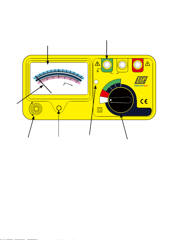
5. LAYOUT
(1)Terminal
(2)Scale
(3)Pointer
(4)Test Button
(5)Zero adjust screw
(6)LED
(7)Function switch
ACV
6
8
10
12
4
2
0
0
5
10
15
20
25
30
Ω
BATT
GOOD
E P C
EARTH
VOLTAGE
BATT
CHECK
MAX.AC30V
CAT. IV 30V
Ω
X100
X10
X1
ALWAYS ENSURE CIRCUIT
TO TEST IS FREE OF VOLTAGE
BEFORE PROCEEDING
T1105
EARTH RESISTANCE TESTER
LOCK
PRESS TO TEST
(5)
(4)
(3)
(6) (7)
(1)
(2)

-6-
6. MEASURING METHODS
BEFORE MEASURING, READ SAFETY NOTES ON
PAGE 2.
WARNING
Before testing.
● Check to see if the meter pointer is adjusted
exactly to the mechanical zero position of the
Ω or V scale. If not, turn the zero adjust screw
with ascrewdriver.
● Rotate the function switch to the "BATT.
CHECK" position and press to test. Battery
voltage is sufcient when the meter pointer
stays in "OK" position of the battery check
scale. If not, replace with the new batteries.
(1) Earth Voltage Check
a. Test leads connection
ACV
6
8
10
12
4
2
0
0
5
10
15
20
25
30
Ω
BATT
GOOD
E P C
EARTH
VOLTAGE
BATT
CHECK
MAX.AC30V
CAT. IV 30V
Ω
X100
X10
X1
ALWAYS ENSURE CIRCUIT
TO TEST IS FREE OF VOLTAGE
BEFORE PROCEEDING
T1105
EARTH RESISTANCE TESTER
LOCK
PRESS TO TEST
Fig.1
Green
Earth
Electrode
under test
Auxiliary
Earth
Spikes
Yellow
E P

-7-
ACV
6
8
10
12
4
2
0
0
5
10
15
20
25
30
Ω
BATT
GOOD
E P C
EARTH
VOLTAGE
BATT
CHECK
MAX.AC30V
CAT. IV 30V
Ω
X100
X10
X1
ALWAYS ENSURE CIRCUIT
TO TEST IS FREE OF VOLTAGE
BEFORE PROCEEDING
T1105
EARTH RESISTANCE TESTER
LOCK
PRESS TO TEST
b. Rotate the function switch to "EARTH
VOLTAGE" position. Earth voltage will be
indicated on the ACV scale.
When the earth voltage is more than 10V, it
may result in errors in earth resistance
measurement. Accurate earth resistance
measurement may not be made.
(2) Earth resistance measurement
a. Connect green, yellow and red test leads to
Instrument terminals E, P and C, with auxiliary
earth spikes P1, C1.
Stick the auxiliary earth spikes P1 & C1 into the
ground properly and deeply. Both of the P1 &
C1 spikes should be aligned from the earthed
electrode under test. The interal should be
5~10m(Fig.2).
The measured results may be inuenced by
induction if measurements are made with the test
leads twisted or connected to each other. When
connecting the probes, they should be separated.
Fig.2
Red
Green
5~10m 5~10m
Earth
Electrode
under test
Auxiliary
Earth
Spikes
Yellow
E P
C
P1 C1

-8-
b. Rotate the function switch to proper range, then
press the push-button to test and take the
reading.
(3) Simplied earth resistance measurement method:
a. This method is recommended where an earth
resistance higher than 10Ω is measured or
where it is not possible to drive auxiliary earth
spikes. An approximate value of earth
resistance can be obtained by the two-wire
system as shown in Fig.3.
b. Rotate the function switch to "EARTH
VOLTAGE" position and press to test. Make
certain that earth voltage is less than 10V.
c. First rotate the function switch to "x10" position
and press to test. Read earth resistance. If the
meter pointer indicates over full scale, switch to
"x100" position and read earth resistance.
d. The reading obtained (Rx) is an approximate
earth resistance value. There is no need for
external shorting since P and C terminals are
shorted by using the test leads specied for the
simplied measurement.
Fig.3
Green
Red
Rx=Re-re
Rx
re
E
PC
Secondary
Side
Supply
Transformer
Where earth for mains
power supply used.
Earth
Electrode
under test
Primary
Side

-9-
e. Rx = Re - re
Rx = True Earth Resistance
Re = Indicated Value
re = Earth Resistance or Earth Electrode.
f. Since the measuring current is as low as 2mA,
the earth leakage breaker (ELCB) does not trip
even if the earth side of the commercial power
supply with an ELCB is used.
Press lamp switch to turn on the lamp. The lamp
will automatically shut off after 10 seconds
Follow the proper connection as shown in Fig.2.
The LED (red) indicator will be lit.
This proves that a correct current circulation is
under its operation.
-10-
7. MAINTENANCE
● Battery replacement:
When setting the function switch to the "BATT.
CHECK" position and the meter pointer does NOT
stay in "OK" position, replace the batteries as
follows:
(1) Disconnect the test leads from the instrument
and turn off the power.
(2) Use a screwdriver to unscrew the screw on back
cover then slide away the cover out. Take out
the batteries and replace with new batteries,
type SUM-3 (R6P).
(3) Place back cover and secure bay with screw.
● Cleaning and storage:
WARNING
To avoid electrical shock or damage to the meter,
do not get water inside the case.
Periodically wipe the case with a damp cloth and
detergent. Do not use abrasives or solvents.
If the meter is not to be used for periods of longer
than 60 days, remove the batteries and store them
separately.

-11-
CAT IV - Is for measurements performed at the
source of the low-voltage installation.
CAT III - Is for measurements performed in the
building installation.
CAT II - Is for measurements performed on circuits
directly connected to the low-voltage
installation.
CAT I - Is for measurements performed on circuits
not directly connected to Mains.
Due to our policy of constant improvement and development, we reserve the
right to change specications without notice.
Table of contents
Other Top Tronic Test Equipment manuals


Popular Test Equipment manuals by other brands


Steren
Steren MUL-450 user manual

Hantek
Hantek IDSO quick guide

inTest
inTest Temptronic ThermoStream TP04300 Series Operator's manual

Baker Instrument Company
Baker Instrument Company D6000 DIGITAL TROUBLESHOOTING PROCEDURES & FAULT LISTING

Aeroflex
Aeroflex 2975 Operation manual

Besantek
Besantek BST-ELC06 instruction manual