An ISO 9001:2008 Company
®
All Specifications are subject to change without prior notice
D:\Chhaya\My Documents\Chhaya\backup\catlog\New Cat\KM 1320-3000B.cdr
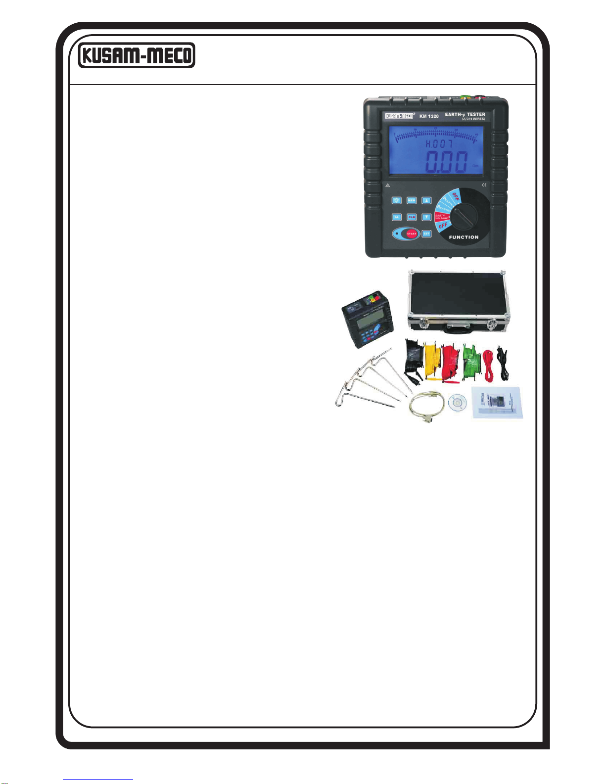
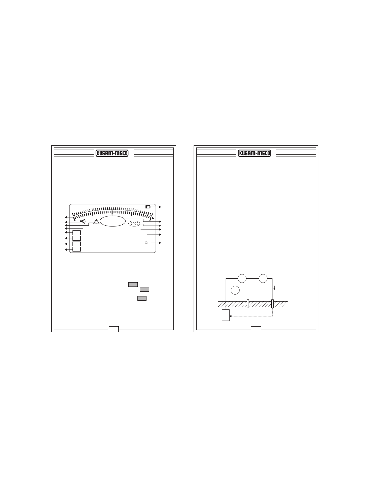
Earth Resistance Soil Resistivity Tester
2 / 3 / 4 Wire Model KM 1320
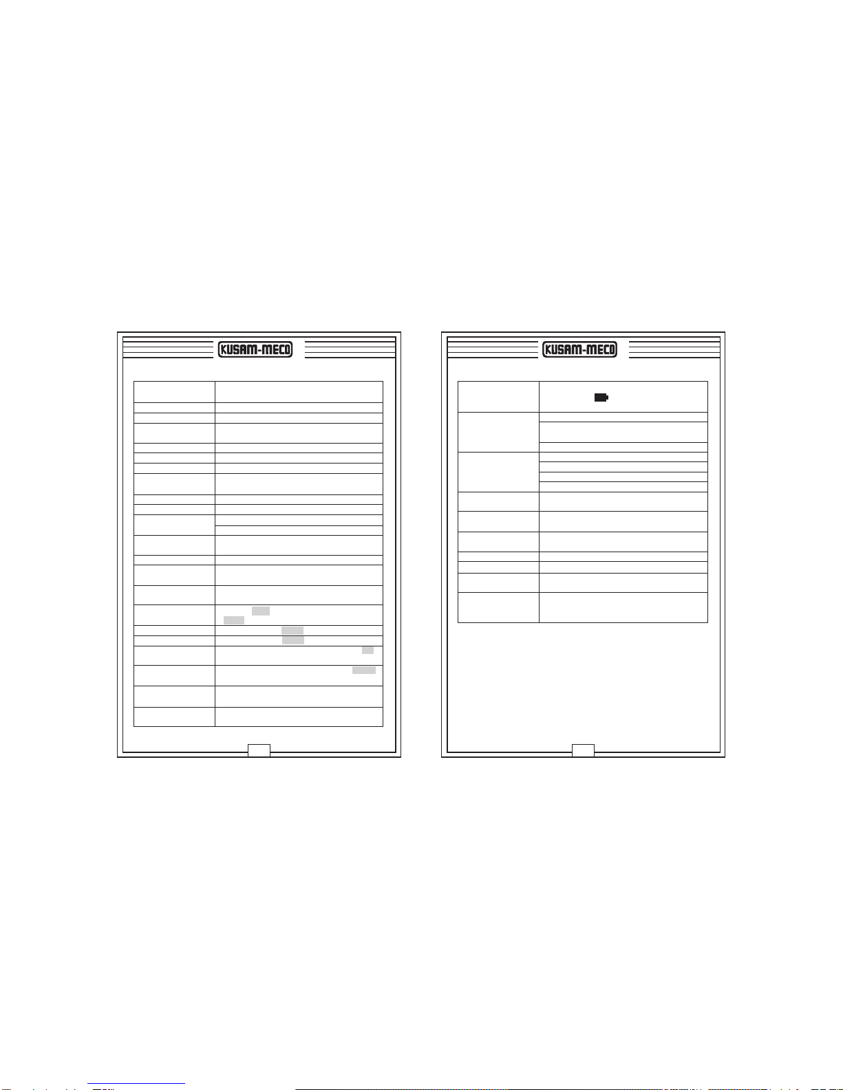
?Function : Measurement of 2/3/4-pole earth resistance, soil resistivity, earth voltage, AC voltage
?Measurement Range : Earth Resistance: 0.00Ω-30.00kΩ
Soil Resistivity: 0.00Ω-9000kΩ
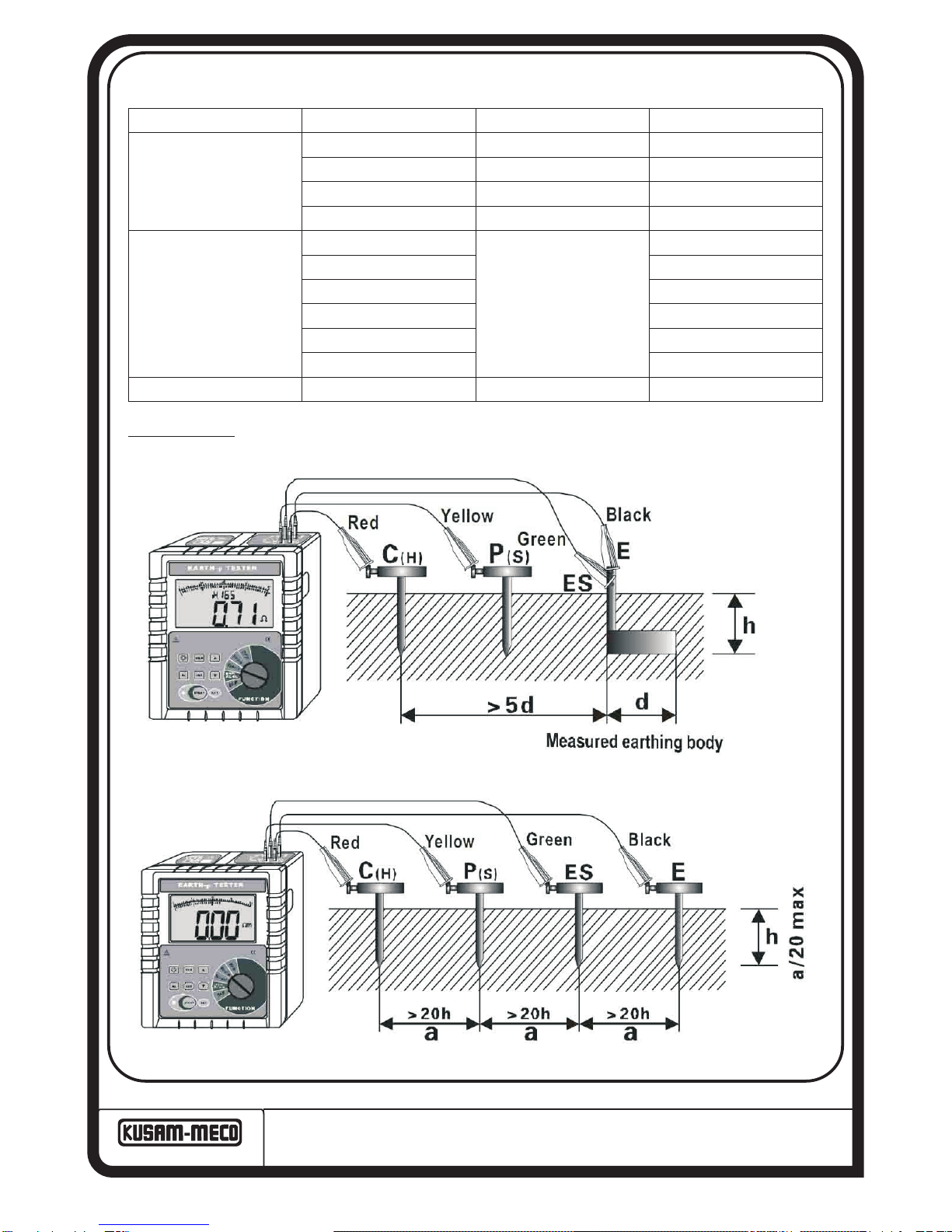
?Measuring Mode : Precise 4-pole measurement, 3-pole measurement, simple 2-pole measurement
?Measuring Method : Earth Resistance: rated current change-pole method, measurement current 20mA Max
Soil Resistivity: 4-pole measurement
Earth Voltage: average rectification(between P(S)-ES)
?Test Frequency : 128Hz/111Hz/105Hz/94Hz(AFC)
?Short-circuit Test Current : AC 20mA max
?Open-circuit Test Current : AC 40V max
?Test Voltage Wave : Sine wave
?Electrode Distance Range: Can be set 1m-100m
?Shift : Earth Resistance: 0.00Ω-30.00kΩ,automatic shift
Soil Resistivity: 0.00Ω-9000kΩ, automatic shift
?Backlight : Blue screen backlight, suitable for dim places
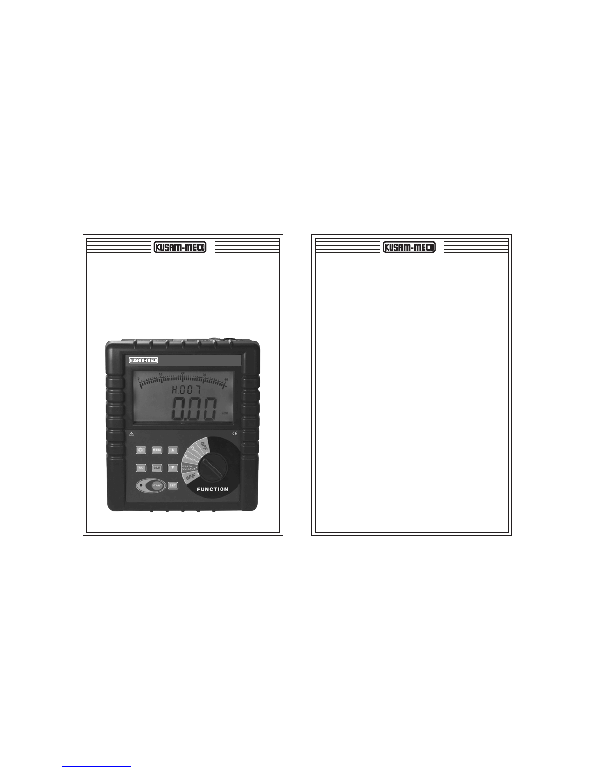
?Display Mode : 4-digital super-large LCD display, blue screen backlight
?Measuring Indicator : During measurement, LED flash indicator, LCD count down display, progress bar indicator
?LCD Frame Dimension : 128mm×75mm
?LCD Window Dimension : 124mm×67mm
?Standard Test Wire : 4 wires: each for red 20m, black 20m, yellow 10m, and green 10m
?Simple Test Wire : 2 wires: each for red 1.6m and black 1.6m
?Auxiliary Earthing Rod : 4 rods: Φ10mm×150mm
?Measuring Rate : Earth voltage: about 3 times/second
Earth resistance, soil resistivity: about 5 seconds/time
?Line Voltage : below AC 600V
KM 1320 Earth Resistance Soil Resistivity Tester is specially
designed and manufactured for measuring earth resistance, soil
resistivity, earth voltage, AC voltage. Adopting the latest digital
and micro-processing technology, precise 4-pole, 3-pole and
simple 2-pole method for earth resistance measurement,
importing FFT and AFC technology, with a unique function of
anti-interference capability and the ability to adapt to the
environment, consistency of repeat testing, to ensure high
precision, high stability and reliability for prolonged measure,
which is widely used in electric power, telecommunications,
meteorology, oil field, construction, lightning protection,
industrial electrical equipment and other earth resistance, soil
resistivity, earth voltage, AC voltage measurement.
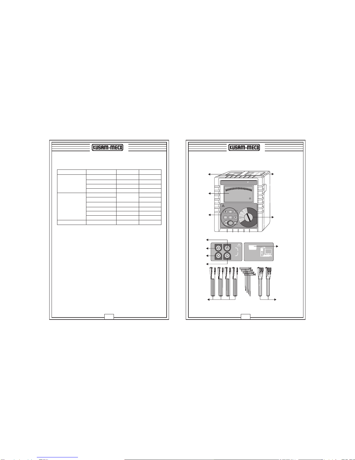
KM 1320 Earth Resistance Soil Resistivity Tester is composed
of host machine, monitoring software, testing wires, auxiliary
ground pillars, communication wires and others. The large LCD
display of host machine is with blue backlight & bar graph
indicating that can be seen clearly. At the same time it can
store 300 sets of data, fulfilling historical inquiry and online real-
time monitoring through monitoring software, dynamic display,
alarm indicator, and with the functions like historical data
access, reading, preservation, report forms, printing and so on.
GENERAL SPECIFICATIONS :