DELTA 2000 SA Operating manual - English
2 Copyright Silca 1998
GENERAL INSTRUCTIONS
The DELTA 2000 SA key-cutting machine has been designed according to the specifications of the
Machine Directives. From the design stage risks for the operator have been eliminated in all areas:
transport, regulation, cutting and maintenance.
The use of protective goggles is compulsory during cutting operations, as indicated on the machine
itself and in this manual.
The material used in the manufacture of this machine and the components employed during use of the
machine are not dangerous and their use complies with standards.
USE
The DELTA 2000 SA key-cutting machine must be installed and used in the way laid down by the
manufacturer, as illustrated in this manual.
If the machine is used differently or for purposes different from those described in this manual, the
customer will forego any rights he may have over SILCA S.p.A. Furthermore, unforeseen danger to the
operator or any third parties may arise from incorrect use of the machine.
Negligence in the use of the machine or failure on the part of the operator to observe the instructions
given in this manual are not covered by the guarantee and the manufacturer declines all responsibility
in such cases.
It is therefore indispensable to read the operating manual carefully in order to make the best use
of the DELTA 2000 SA key-cutting machine and benefit from its potential.
FURTHER RISKS
There are no further risks arising from the use of the DELTA 2000 SA key-cutting machine.
PROTECTION AND SAFETY PRECAUTIONS FOR THE OPERATOR
The DELTA 2000 SA key-cutting machine is built entirely to standards. The operations for which it has
been designed are easily carried out at no risk to the operator.
The adoption of general safety precautions (use of protective goggles) and observation of the
instructions provided by the manufacturer in this manual eliminate all human error, unless deliberate.
The DELTA 2000 SA key-cutting machine is designed with features which make it completely safe in all
its parts.
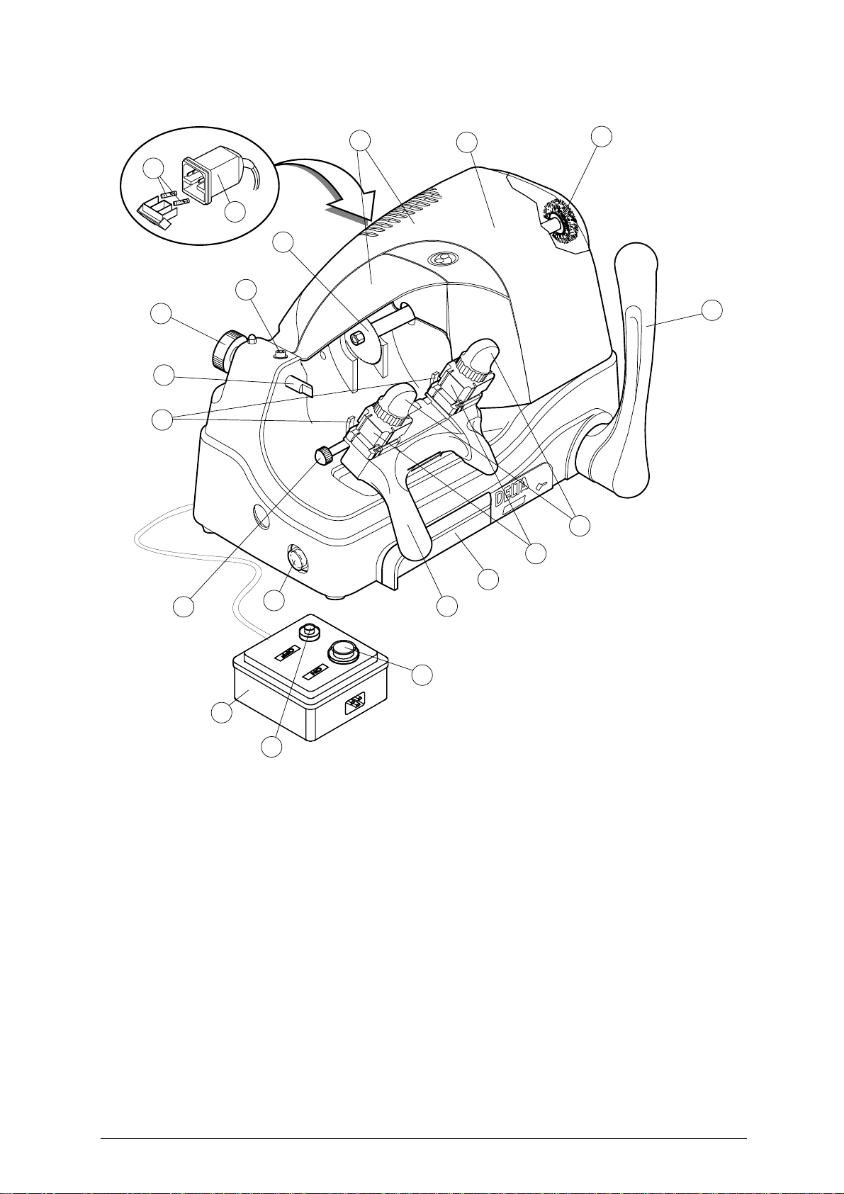
• Power supply
The key-cutting machine must be supplied with electricity by means of a safety device (*). The plug
must be earthed.
• Start-up
The machine is started up by means of:
1) the START button on the safety device (*);
2) the ON switch, situated on the machine, which activates the machine motor.
• Maintenance
The operations to regulate, service, repair and clean the machine have been devised in the simplest
and safest way possible. There is no danger of removable parts being replaced wrongly or unsafely.
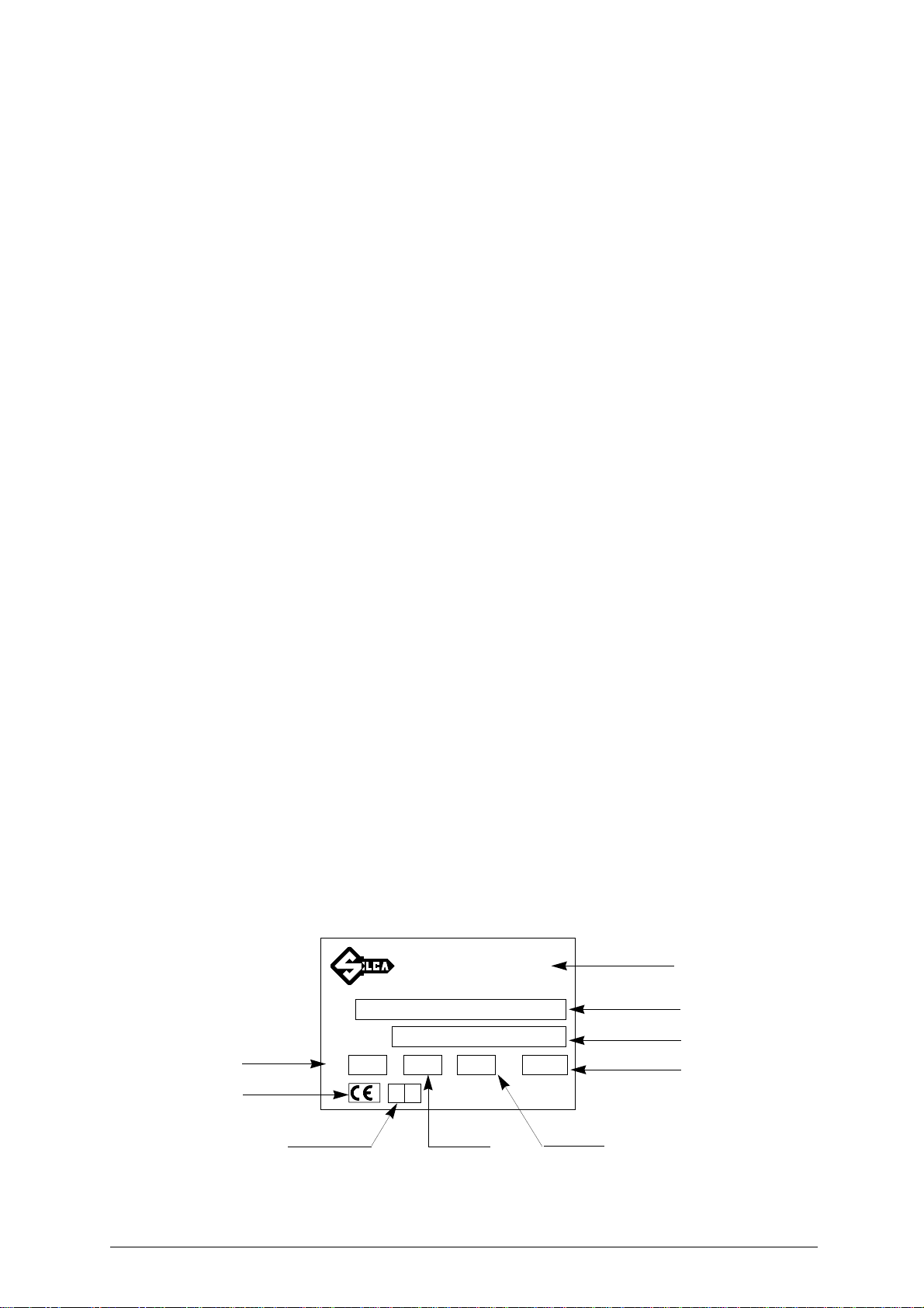
• Machine identification
The DELTA 2000 SA is provided with an identification label which shows the serial number (fig. 2).
ATTENTION: should the machine be left on continuously for over 50 minutes, the cutting tool motor is protected
against overheating and will automatically cut out.
In such cases, proceed as follows:
a) turn off the master switch (E);
b) let the motor cool for at least 2 hours before using the machine again.
Fig. 2
N˚ MATRICOLA
SERIAL No.
Telefax (0438) 913800
Telex 410579 SILCA I
SILCA S.p.A. - Via Podgora 20 (Z.I.)
31029 VITTORIO VENETO (TV) ITALY
TIPO
TYPE
VOLT A.
Hz. WATT
(0438) 9136
☎
Manufacturer’s
identity
Serial No.
Type of machine
Absorbed power
Working
frequency Absorbed
current
Year of
manufacture
CE mark
Working
voltage
®