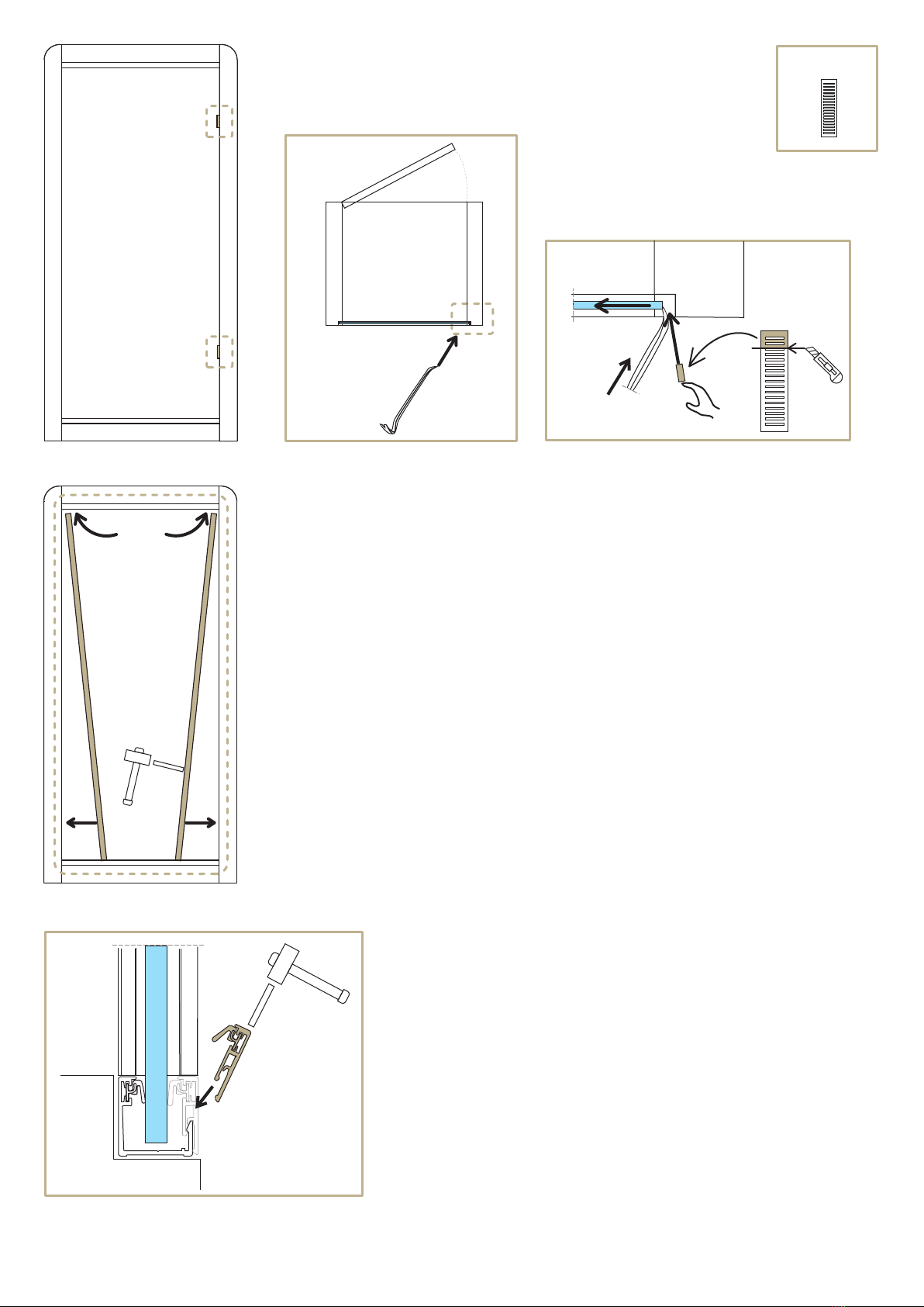
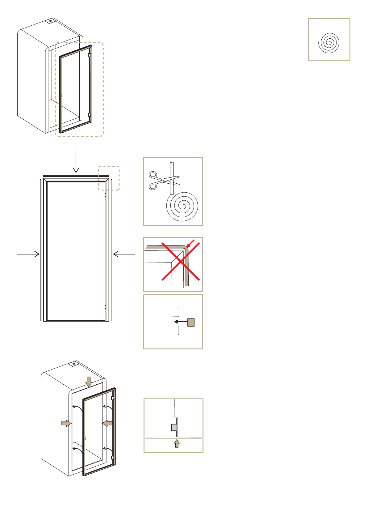
silen Space 1 User manual

silenspace.com
Silen Space 1
Assembly Manual
RIGHT HANDED

Ax1
Hx1
Dx1
Kx1
Ex2G1 x2
Fx2
G2 x2
Lx1
Jx1
Rx1
Px3
Bx1
Gx1
Cx1
Mx2 Nx2
2106mm
1096mm
1140mm
894mm
1
A
EE
F
F
B
C
G
H
J
K
L
M
N
P
P
P
R
G1
G1
G2
G2
D
M
N

f x1
e x1
3,5x35mm
T15
T25
T15
d x4
4,5x50mm
c x8
M10
5x60mm
a x4
b x4
2
TOOLS:
g x8
k x1
h x1
m x1
5
min
2350mm
NB!
Suction cups
min. 2x120mm 2pcs Level 1pcs Scissors 1pcs
Stepladder 1pcs
Utility knife 1pcs
Crowbar 1pcs Plastic Block 1pcs
Wrench 10mm 1pcs
Cordless drill with
drill bits set
Rubber mallet 1pcs
Screwdriver 1pcs
Vacuum cleaner 1pcs
Ratcheting wrench with
long 5mm Allen key
Cleaning supplies 1set
300L extrastong trash-
bags 5pcs
2-10mm 1set

3
A2.
2.
3.
3. B
A
1.
1.
1.
1.
2.
2.
1.
3.
3.
C

M10
a x4
4
85
85
120
120
510
1.
A
85
85
540
120
120
A
A
5mm
2.
A
B
3.
AB
10mm
a
1. Remove carpet plugs on marked positions and use
a long 5mm allen key to adjust 4 levelling glides in the
corners to avoid the floor module from shifting during
assembly
Note! Glides must be lowered minimally.
2. Insert the positioning rods attached to side modules
(B and C) into the floor module positioning holes.
3. Secure side modules to the floor
module using part “a” and tighten it
with 10mm wrench.
Note! Make sure there is no gap between
the side and floor module beams.

5
4.
6.
B
D
B5.
F
E
b
T25
5x60mm
bx4
E
F
5. 6.
4.
4.
B
D
EF
5.
4.
4.
C
4. Attach assembly support beams (E)
to the side modules.
5. Place safety support beams (F) on top
of the assembly support beams (E).
6. Lift ceiling module (D) on top of the side
modules (B and C) and secure the ceiling
module by lowering it between the side modules
until connectors are even to each other.

6
8.
7.
8.
7. F
F
E
E
L
B
B
L
7. Remove support beams (E) and (F) after
ceiling module is attached.
8. Connect the electrical fittings between side module (B)
and table (L), then place table on top of the pre-installed
laths on side module.

7
9.1
9.
9.2
1.
2.
D
G
A
3.
A
B
G
C
D
DG2
G2
G2
G1
G1
9.1 Click in profile (G2) to the ceiling module using a rubber mallet
and plastic block to secure it.
9. Back-glass panel installation:
9.2 Place the back-glass panel (G) into the aluminum profiles:
Step 1. Lift the glass panel (G) into the top aluminum
profile using suction cups,
Step 2. Push the bottom of the glass panel (G) towards
the front of the cabin,
Step 3. Carefully lower the glass panel (G) until it
stands on spacers pre-installed into bottom
aluminum profile.

e x1
8
9.5
9.3
9.4
G2
G2
G1G1
G
9.3
9.3
G2
A
G
C
G
e
BC
NB!
FRONT
9.3
BACK
9.3 Secure the back-glass panel by wedging two shims “e” between
the glass panel (G) and the wooden spacer making sure they
are tight.
Note! Shims “e” must be cut into fitting size first.
Carefully shift the glass panel with a plastic crowbar to create
clearance for the shims “e”.
9.4 Click in profile (G1) to the side modules using a rubber mallet
and plastic block to secure it.
9.5 Click in profile (G2) to the floor module using a rubber mallet
and plastic block to secure it.
Note! Glass panels MUST be shimmed for door to function
properly!
Note! Slide the vertical profile (G1) up between the top profile and
side module.

H
10.1
f
f
f
NB!
9
H
NB!
f x1
Hff
f
10.2
H
H
10. 10. Door frame installation:
10.1 Attach expanding tape “f” to the sides
and top of the door frame (H).
10.2 Position the door frame (H) in the front
opening and shift it evenly between side
modules.
Note! Expanding tape must be cut in the corners,
not curved around the corners.
Note! Make sure the front face of the door
frame(H) is in line with the front face
of the side modules.

T15
3,5x35mm
d x4
g x8
T15
4,5x50mm
c x8
10
10.3
10.5
10.6
J
A
H
J
H
A
10.4
c
g
d
c c
c c
c c
c c
ddd
d
10.3 Drive in screws (c) to attach the door frame (H)
to the side modules.
Cover the openings with plugs (g).
10.4 Drive in screws (c) to attach the door frame (H)
to the floor module.
10.5 Remove protection tape from decorative
door threshold (J).
10.6 Attach threshold with glue covered side to door frame.

11
K
NB!
HK
11.
H
H
3mm
4mm
H
K
11.1
11.2
11.3
11. Door glass installation:
11.1 Remove the covering plate from the hinges using a 3mm allen key
to unlock the pin.
11.2 Use 4mm allen key to remove the securing plate from hinges.
11.3 Use suction cups to lift door-glass panel (K)
to the hinges.
Note! Check if the door-glass panel (K) is straight.
If the glass has a curve to it, determine the
inside and outside by using a long straight
level tool.

12
11.4
K
6mm
6mm
6mm
6mm
H
H
H
11.4
K
11.5
11.6
H
4mm
K
Max 15Nm
11.4 Door-glass panel (K) must be equally centered in
relation to all four sides with approximate 6mm
gap between the glass and door frame.
11.5 Fix the glass by attaching the securing plate back
on the hinges using a 4mm allen key.
11.6 Reattach the covering plate on top of door frame hinges.

3mm
4mm
13
h x1
h
h
h
m x1
m
m
12.1
12.3
12.2
12.
Note! Before lock and handle installation see
manual „Switching the handedness on a lock case“
12. Lock and handle installation:
12.3 Use 4mm allen key to open the rest of the lock assembly “m”.
12.2 Attach the dedicated tool provided with lock assembly “m” to handle “h”
to remove the lock assembly “m” cover plates.
12.1 Use 3mm allen key to open the preassembled handle set “h”.

14
4mm
2mm
2mm
m
12.4
K
K
HNB!
NB!
3mm
h
hh
m
m
12.5
12.6
K
K
12.4 Place the lock assembly “m” on door-glass and
secure bolts with 4mm allen key.
Note! Make sure part “m” is positioned at a 90-degree angle
in relation with door-glass edge.
12.5 Reattach the cover plates on lock assembly “m” using the
dedicated tool with handle “h”.
12.6 Attach handle “h” to lock assembly “m” using 3mm allen key.
Make sure the plastic fasteners are covered with provided
metal covers on both sides.
Note! Handle with the spindle must stay inside the cabin
for safety measures.
In case of emergency you must be able to open the door to exit.
INSIDE
INSIDE
INSIDE

15
13.
13.1
13.2
13.2
13.2
13.3
13.3
13.4
13.4
M
M
N
N
P
R
P
P
M
N
R
P
NB!
1mm 1mm
P
N
13. Covering trim installation:
13.1 Attach engraved covering trim (R) on the front side of ceiling module.
13.2 Attach covering trims (P) on the front/back side of floor module and
back side of ceiling module.
13.3 Attach covering trim (M) on the front/back side of side module and
connect it with pins attached to part (R) and (P).
13.4 Attach covering trim (N) on the front/back side of side module and
connect it with pins attached to part (R) and (P).

A
5mm
min
A
16
14.
14. 14. 14.
14.
A
A
14. 14. To relocate the cabin, lift up previously lowered levelling glides and
move it to desired location. Repeat step 1. to secure the cabin again.
Note! Also adjust the middle glide so it supports the middle of the floor.

17
k x1
Schematic 1.
D
B
B
B
A
D
k
15.
16.
NB!
15. Clean all the interior and exterior surfaces.
16. Remove cover plate from the ceiling module
and continue based on one of the following options:
Option 1: To connect the „Space” to general power supply
with bottom connector use Schematic 1.
Option 2: To connect the „Space” to general power supply
with top connector use Schematic 2.

18
NB!
B
B
B
A
D
k
17.
Schematic 2.
17. Make sure LED lights and power socket are functioning properly
and your product is ready for use.
Thank you for choosing Silen Space.

SilenOÜ
Veerenni 38, Tallinn
ESTONIA
silenspace.com
Other manuals for Space 1
1
Table of contents
Popular Indoor Furnishing manuals by other brands

LapCabby
LapCabby Lyte MD instructions

baby&child
baby&child Antique Steamer Trunk Wide Dresser Assembly instructions

Osmond Ergonomics
Osmond Ergonomics Adapt 600 instructions

Alice's Home
Alice's Home MIKA IMKBUFFET160WD Assembly instructions

Moon Valley
Moon Valley M-1500 Assembly instructions

Whittier Wood
Whittier Wood Addison 1116DUET manual