Silent Sentinel Osiris PT User manual


OSIRIS INSTALLATION GUIDE
Commercial in Confidence 2/26
Silent Sentinel Limited reserves all the right. All in this manual including texts, pictures,
diagrams, and other contents belong to Silent Sentinel Limited. Without the written
permission, no one shall copy, photocopy, translate or disseminate all or part of this manual.
This manual is used as a guide. The photos, graphics, diagrams, and illustrations provided in
the manual are only used for explanation, which may be different from the specific product.
Please refer to the actual product. We try our best to make sure all the contents in this manual
are accurate. We do not provide any representations or warranties in this manual.
If you need the latest version of this manual, please contact us. Silent Sentinel recommends
that you use this manual under the guidance of professionals.
Version Control
Version
Author
Approver
Date
0.1
James Carlton-Long
James Carlton-Long
10/08/2021
1.0
James Carlton-Long
Matthew Short
12/08/2021

OSIRIS INSTALLATION GUIDE
Commercial in Confidence 3/26
Contents
System Overview ...............................................................................................................................................5
Overivew ........................................................................................................................................................5
Power / Interface Requirements ...................................................................................................................5
System Orientation........................................................................................................................................6
Mechanical Installation......................................................................................................................................7
Overview ........................................................................................................................................................7
Fixtures and Fittings;......................................................................................................................................7
Mounting the Jaeger PTU ..............................................................................................................................8
Attaching the Side Payloads ........................................................................................................................10
Wiper Assembly Installation ............................................................................................................................12
Overview ......................................................................................................................................................12
Fixtures and Fittings.....................................................................................................................................12
Boresight Guide................................................................................................................................................15
Overview ......................................................................................................................................................15
Horizontal Adjustment.................................................................................................................................15
Vertical Adjustment .....................................................................................................................................16
ANNEX 1 - Cable Information...........................................................................................................................17
Cable Overview ............................................................................................................................................18
Cable Pin Out ...............................................................................................................................................18
ANNEX 2 - Physical Connectors........................................................................................................................19
Osiris Base Connector..................................................................................................................................19
Side Payload Mounting Connector. .............................................................................................................20

OSIRIS INSTALLATION GUIDE
Commercial in Confidence 4/26
INSTALLATION SHOULD BE CARRIED OUT BY QUALIFIED PERSONNEL ONLY IN ACCORDANCE WITH THE
APPLICABLE LOCAL CODES.
THE MANUFACTURER CAN ACCEPT NO LIABILITY FOR ANY DAMAGES OR LOSSES CAUSED DUE TO
INCORRECT OR IMPROPER INSTALLATION.
Safety Information
Before installing the equipment, please read this guide carefully.
Installation of this product should only be carried out by a competent and suitably qualified
engineer. If you are in doubt, you should refer the installation to a suitably qualified person.
To prevent electrical shock hazards, disconnect the power from electrical sources before working
on the equipment.
Make all connections with the power turned off. Do not make or remove connections when the
power is turned on. Before using the product ensure that all cables are correctly connected and
that the power cables are not damaged.
Ensure that the product is secured correctly in all situations. Do not place the equipment on to a
trolley, table desk or other platform that is not stable; to avoid the product from falling over.
Ensure that the power supply to be used is correct for the equipment and the correct input voltage
for your region. If unsure, contact your local power supply company. If the power supply or cables
are broken, do not use them. Contact a qualified electrical services technician or your retailer.
1. Do not use any equipment that appears damaged or incomplete. If you detect damage,
contact your dealer immediately.
2. Do not allow connectors to be exposed to long-term water immersion.
3. Do not allow electrical contacts or leads to be exposed to dust, humidity or moisture. Do not
allow electrical contacts or cable-ends to become wet.
4. The equipment must be firmly secured using appropriate fixings and fastening as
appropriate to the mounting surface that the unit is being affixed to.
Notes:
1. Do not open the camera unit, doing so invalidates the unit’s warranty.
2. Do not back-drive the pan or tilt axis of the camera. To do so will damage the motor drive
mechanism and will invalidate the warranty.
3. Do not use caustic or abrasive cleaning products on the unit.
4. In situations where there could be a risk of injury should any part of the assembly become
detached for any reason and fall, normal safety precautions should be employed.
5. Use only the power source types indicated in this user guide or provided with the unit.
6. All power supplies should be appropriately fused.
7. Take extra care lifting or moving units due to their weight.
8. The central PT unit should be installed by itself with no payloads attached. The
camera/sensor and Radar payloads fitted individually, after it has been secured.
9. Take care to allow space around the unit for Pan and Tilt motion.
10.Take care to avoid striking persons or objects when the camera is in motion.
11. Not fitting the provided sun shields will invalidate the systems warranty.
12.This guide only concerns itself with the Mechanical Installation of the System.

OSIRIS INSTALLATION GUIDE
Commercial in Confidence 5/26
System Overview
Overivew
The Osiris PT system generally comprises of;
1. The Osiris PT Unit
2. QTY1 EO (Daylight Camera)
3. QTY1 Ti (Thermal Camera)
However, as the Osiris is a highly modular platform the number and nature of payloads may vary
from unit to unit. This Installation Documentation only considers the standard system as noted
above. If there is ANY uncertainty brought about by other combinations of payloads then Silent
Sentinel should be consulted prior to any installation efforts.
Power / Interface Requirements
Input voltages 28VDC (26-32 VDC)
Power 70W (150W peak) Standard payloads.
100W (150W peak) Large / Dual payloads.
These figures do not include the requirements of any large payloads, optional heating or cooling
devices added within the camera enclosures, nor optional infra-red lighting systems.


OSIRIS INSTALLATION GUIDE
Commercial in Confidence 7/26
Mechanical Installation
Overview
The system should be installed in the following order;
1. Pan / Tilt securely mounted to the Mast / Installation Location
2. Side Payloads
3. Cable / PSU
Note: The system should not be powered on when any of the payloads are attached.
Fixtures and Fittings;
The followings fittings are providing with the Jaeger System.
Figure 3 Jaeger Fittings
1. Sun Shield Fixings;
a. QTY4 –M4x10
b. QTY4 –M4 Nylon Washers
2. Side Payload Fittings;
a. QTY8 –M5x10
i. QTY3 for each Payload
3. Main Osiris Fittings
a. QTY4 –M8x20
b. QTY4 –Spring Washers
4. Duralac
a. To be used on all threads
Figure 4 - Duralac


OSIRIS INSTALLATION GUIDE
Commercial in Confidence 10/26
Attaching the Side Payloads
Note: please ensure you are attaching the payloads to the correct side. Please refer to the System
Overview section for further information.
Step
Detail
1
Protective caps are fitted to the ends of the
shafts to prevent moisture and impact
damage to the electrical connections.
Remove the three securing screws from the
tilt cover cap and remove the cap from the
tilt shaft.
Note: The IP67 protection of the unit is
compromsied whilst this cap is removed
and the payload is unattached.
2
Securely hold the tube and offer it up so
that the alignment holes engage on the
ends of the rods.
Level the tube so that the connector faces
are parallel with no leaning in any direction.
Push the tube inwards, along the alignment
rods such that the connector assembly
engages.
Care should be taken to keep the tube level
so as to reduce the risk of damage to the
electrical plug assembly.

OSIRIS INSTALLATION GUIDE
Commercial in Confidence 11/26
3
Once the tube is fully located on the shaft
the top securing screw should be inserted
and partially tightened – not all the way.
The remaining two screws should be
inserted in to their respective holes and,
once in place, all three tightened fully.
OSIRIS INSTALLATION GUIDE
Commercial in Confidence 12/26
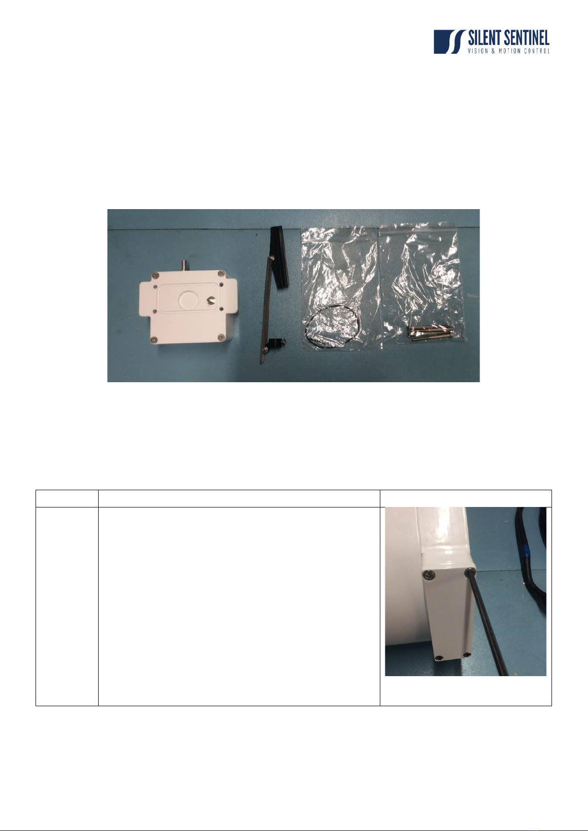
Wiper Assembly Installation
Overview
This guide details the steps involved to install the wiper assembly onto a RHT camera housing.
Fixtures and Fittings
1. Wiper Assembly
2. Wiper Blade
3. O-Ring
4. Fixings
Step
Detail
1
Power down the camera unit and remove the
bottom cover at the front of the camera housing.

OSIRIS INSTALLATION GUIDE
Commercial in Confidence 13/26
2
Insert the supplied O-Ring into the groove on the
wiper box.
3
Align the wiper assembly holes with camera house
jack plug holes
3
Screw the supplied M4x 50 screws into the QTY4
fixing holes. Ensure that the O’ring is seated
properly when screwing together
3
Insert the spring into the wiper assembely shaft.

OSIRIS INSTALLATION GUIDE
Commercial in Confidence 14/26
3
Fit the wiper onto the shaft, locate the wiper at the
desired park position and tighten.
Note: the wiper ‘wipes’ anti-clockwise as you look
at the face of the tube. Therefore, the park position
should be to the right of the window and outside of
the FOV of the camera.

OSIRIS INSTALLATION GUIDE
Commercial in Confidence 15/26
Boresight Guide
Overview
As standard Silent Sentinel factory boresights the cameras ‘parallel’at full tele. Therefore, the
separate between FOV should never be any greater than the separation of the payloads.
However, should it be desired the boresight position can be adjusted externally as detailed below.
Please note, boresight adjustment is carried out on the Daylight camera. The Thermal is fixed
relative to the cameras housing.
It is recommended that the boresight adjustment is carried out at full zoom (full tele).
Horizontal Adjustment
Step
Detail
1
Remove the cover plate from the rear
(Horizontal) adjustment mechanism
to reveal the adjustment wheel and
locking screws.
The cover is secured by four screws
requiring an M3 Allen key tool.
2
Using an M2.5 Allen key, loosen (do
not remove) the two locking grub
screws that are located in the recess
holes either side of the adjustment
wheel.
3
The horizontal action can now be
made by turning the adjustment
wheel using a chisel-tip (slot) screw
driver.
Turn the wheel until the centre-line of
the picture corresponds to the centre
of the target.

OSIRIS INSTALLATION GUIDE
Commercial in Confidence 16/26
Vertical Adjustment
Step
Detail
1
The cover is secured by four screws
requiring an M3 Allen key tool.
2
Using an M3 Allen key, loosen (do
not remove) the locking screw that is
located beside the adjustment wheel.
3
The vertical action can now be made
by turning the adjustment wheel using
achisel-tip (slot) screw driver.
Turn the wheel until the centre-line of
the picture corresponds to the centre
of the target.

OSIRIS INSTALLATION GUIDE
Commercial in Confidence 17/26
ANNEX 1 –Galvanic Kit
Galvanic Kit
Provided with the Galvanic Kit:
1. 4 x M8x20 aluminium bolts
2. Rubber matting for underneath base
3. Aluminium lanyard
The galvanic kit prevents galvanic corrosion from happening on the base on the unit. It isolates the
metal of the unit from the metal of the mast or platform it’s secured on.

OSIRIS INSTALLATION GUIDE
Commercial in Confidence 18/26
ANNEX 2 - Cable Information
Cable Overview
The UCM cable supplied with the Osiris can come in various lengths (up to 50m) and in two
different formats;
1. Double ended;
a. Each end of the Aeron cable is terminated with a UTS6JC14E19S Connector
i. This is typically the case if a pre-terminated PSU is purchased.
2. Bare Ended
a. The Aeron end is terminated with UTS6JC14E19S the Connector
b. The PSU end of the Cable is left as ‘flying leads’ with only the RJ45 and BNC
conductors terminated.
Cable Pin Out
Multiway Cable Conductor Assignments.
Conductor
Function
Conductor
Function
Red
PTZ Power + (Pos) [26-32VDC]
Green/Yellow
Earth (Chassis)
Black
PTZ Power - (Neg)
Grey (Drain wire)
Cable screen – overall multicore shield.
Orange
Aux / Washer Relay Pos – (Specific models only)
Coaxial 1
Composite Video 1 - miniRG59
White
Aux / Washer Relay Neg – (Specific models only)
Coaxial 2
Composite Video 2 - miniRG59
Brown
Pass-through Power Pos
Blue
Pass-through Power Neg
Yellow (UTP)
UTP - RS485 (Data +)
Cat5e - Grey
Net 1 (A) – Ethernet network – PTZ/Side camera
payloads
Blue (UTP)
UTP - RS485 (Data -)
Cat5e - Blue
Net 2 (B) – Ethernet network – Passthrough to top
payload
Netwok connection leads.
Cat5/8P8C pinout configuration –10/100BASET
(TIA568B)
Network connectors.
Pin Function
1 Tx D+
2 Tx D -
3 Rx D+
6 Rx D -

OSIRIS INSTALLATION GUIDE
Commercial in Confidence 19/26
ANNEX 2 - Physical Connectors
Osiris Base Connector
View of the socket face.
EATON
Base Socket: U14EN (UCM)
Cable Connector: UTS6JC14E19S
Contact arrangement: 21-29.
Contacts No.20 and No.25 are Coaxial types for Video transmission.
Installation cable - Contact assignments and conductors (CA-UCM cable).

OSIRIS INSTALLATION GUIDE
Commercial in Confidence 20/26
Side Payload Mounting Connector.
MIL-D38999 G39
View in to Socket face.
Amphenol D38999 Series-III / TV.
PTZ Hub Socket: Amphenol D38999/20FG39SN
.
(Connector on payload: Amphenol D38999/26FG39PN – For attached equipment)
Contact arrangement: G39 / 21-99 - [G39T].
Contact “r” is a Coaxial type for Video transmission on HD-SDI models.
(available on limited pan models only).
Block 2
Pin
(G39A)
Function
Note
Pin
Function
Note
A
Power Positive
12VDC (4A)
c
Ethernet 1 (Rx-)
TIA-568B Gn 6
B
Power Negative / Ground
0V (4A)
d
Ethernet 2 (Rx+)
TIA-568B W/Gn 3
C
Serial 1 (D -) (INV)
Ti side Camera (RS485) (P1)
g
Ethernet 3 (Tx-)
TIA-568B Or 2
D
Serial 1 (D+) (NON)
Ti side Camera (RS485) (P1)
h
Ethernet 4 (Tx+)
TIA-568B W/Or 1
K
Serial 4 (D+)
Aux Comms (IP RS485 +)
i
P2 Comm switcher
(Not Fitted)
L
Serial 4 (D -)
Aux Comms (IP RS485 -)
j
Return-video Signal
For IP encoder cameras
S
Serial 2 (TMU Rx)
Day side Lens/Cam (RS232) (P2)
k
Return-video Ground
For IP encoder cameras
T
Serial 2 (TMU Tx)
Day side Lens/Cam (RS232) (P2)
n
Video CVBS Signal
X
Serial 3 (TMU Rx)
Ti side Lens (RS232) (P0)
p
Wiper Trigger
Y
Serial 3 (TMU Tx)
Ti side Lens (RS232) (P0)
q
Video CVBS Ground
r*
Video HD-SDi
Coaxial contact
(Not Fitted to all types)
Contact identity letters are case sensitive. (* Wide/Coaxial contact)
This manual suits for next models
2
Table of contents


