Silent Witness SW2300 User manual
USER GUIDE
FULL HD VEHICLE RECORDER
•Thank you for purchasing the SW2300 Vehicle Recorder.
•Please ensure that you read and understand this USER GUIDE
and use it before connecting and installing this Recorder.
•Please store the USER GUIDE in an easily accessible location.
VER 1.0.0 1st Edition
SW2300

INDEX
■Safety advice .................................................................................3
■GPS reception.................................................................................4
■Contents...........................................................................................5
■Introduction......................................................................................6
■Functions .........................................................................................8
■LEDs & Buzzer Specification ......................................................10
■INSTALLATION ............................................................................11
■SOFTWARE USER GUIDE ........................................................12
■SOFTWARE INSTALLATION ...................................................13
■Initialize SD Card..........................................................................14
■Settings .........................................................................................15
■PC Viewer Software Viewing Settings.......................................17
■Open the SD card.........................................................................18
■Playback ........................................................................................19
■Log File Playback .........................................................................20
■Save JPEG and AVI File.............................................................21
■Print Image ....................................................................................22
■Backing up Files ...........................................................................23
■GPS Log to KML Converter ........................................................24
■Driver Report ................................................................................25
■Analysis Criteria settings .............................................................26
■Grading Criteria settings ............................................................28
■Grading method ............................................................................31
■Graph display settings .................................................................32
■SPECIFICATION ..........................................................................33
■Appendix Recording time table ..................................................34
■Appendix Upgrade ......................................................................35
■Technical support and Warranty ................................................36
2
SAFETY ADVICE
CAUTION
RISK OF ELECTRIC SHOCK
DO NOT OPEN
CAUTION: TO REDUCE THE RISK OF ELECTRIC SHOCK,
DO NOT REMOVE COVER.
NO USER‐SERVICEABLE PARTS INSIDE.
REFER SERVICING TO QUALIFIED SERVICE PERSONNEL.
Please make sure you follow the safety advice/instructions given in the user guide.
Caution
RISK OF EXPLOSION IF BATTERY IS REPLACED BY AN INCORRECT TYPE.
DISPOSE OF USED BATTERIES ACCORDING TO THE INSTRUCTIONS.
Battery for RTC(Real Time Clock) inside
Caution
Install the product where it does not block driver’s visibility and where there
is no airbag installed. This could cause an accident or might injure passengers
in case of accident
Caution
Damages due to production malfunction, loss of data, or other damages occurring
while using this product shall not be the responsibility of the manufacturer.
Although the product is a device used for recording videos, the product may not
save all videos in the case of a malfunction. In the case of an accident, the sensor
may not recognize the shock when the impact is light and as a result it may not
begin recording automatically.
WARNING:
TO PREVENT FIRE OR ELECTRIC SHOCK HAZARD, DO NOT EXPOSE
THIS APPLIANCE TO RAIN OR MOISTURE.
GPS RECEPTION
1. Activate the product in an area without large buildings to
improve GPS reception.
The commercial purpose GPS has the average rage error of more
than 15 meters and the range error could be more than 100 meters
due to environmental conditions like buildings, roadside trees etc.
2. The temperature range for optimum operation of the
GPS receiver in your car is ‐10 ~ 50°C.
3. When using the product for the first time or after a long
period (more than three days), it may take a little longer
to recognize your current location.
It may take between five and thirty minutes to get GPS reception.
GPS reception may be impaired under the following circumstances
1) If there is an object at the end of the GPS antenna
2) If your vehicle has metallic elements on the windshields
3) If equipment generating electromagnetic waves that interfere with the GPS
signal is installed in the vehicle e.g.: Other GPS devices such as a certain type
of wireless activated alarms, MP3 and CD players and camera alarms using
GPS.
4) If you are using a receiver connected by cable, electric interference can be
avoided by simply changing the location of the receiver (antenna).
5) On heavily overcast or cloudy days, if the vehicle is in a covered location
such as under a bridge or raised roadway, in a tunnel, an underground
roadway or parking area, inside a building or surrounded by high‐rise
buildings.
6) If GPS signal reception is poor, it may take longer to locate your current
position when the vehicle is moving than when it is stationary.

4
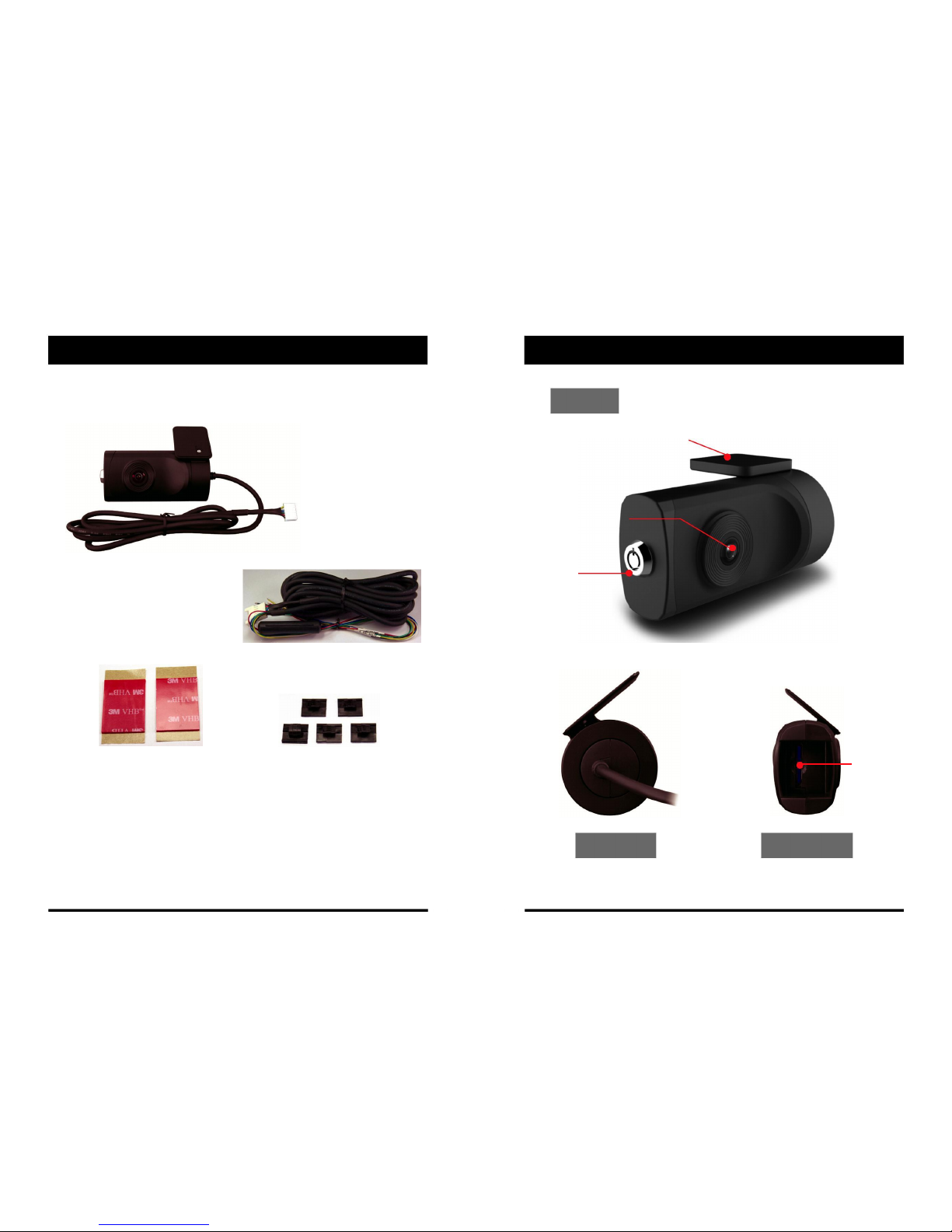
CONTENTS INTRODUCTION
FRONT
Bracket
Camera Lens
SW2300 Lock
Vehicle Recorder
Power Cable
Sticker for Windscreen mounting
SD
Wire Splice clips (x5)
Memory
(double sided tape x1)
Card Slot
Left side Right Side

56
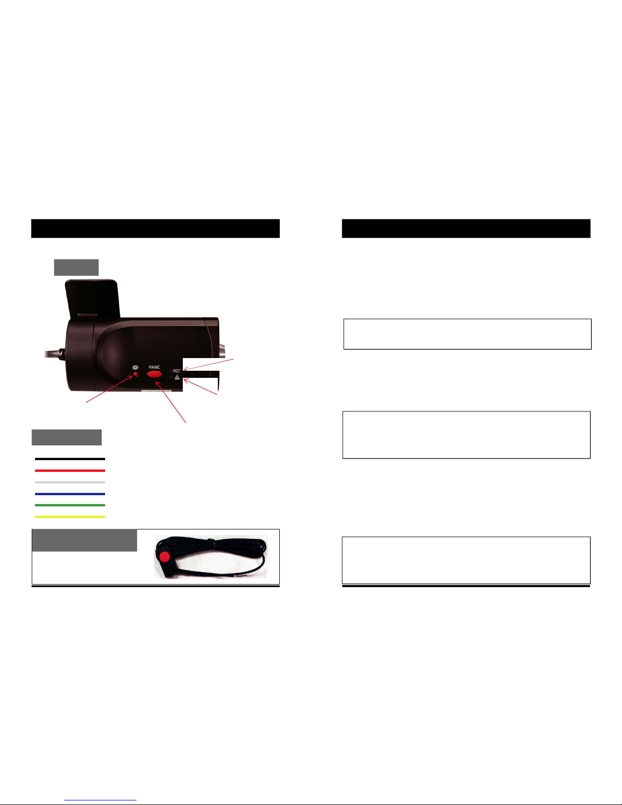
INTRODUCTION
BACK
Record LED
BLUE LED
Warning LED
G‐Sensor Calibration button
RED LED
Panic Record Button
Power Cable
Black (Ground)
Red (Power +)
White (External panic button+ )
Blue (External panic button ‐)
Green (Alarm out1), Low(0V) to High (5V) 2seconds
Yellow (Alarm out2), Low(0V) to High (5V) 2seconds
External Panic Button
(optional Item)
Cable length: 2m90cm
Button Case Size: 18 x39x10 mm
FUNCTIONS
Automatic Booting
Once the SW2300 has been wired to your car power source the SW2300 will be
boot up, this will take around 1 minute for the unit to be ready to record.
The default setting for record is the continuous recording at 30fps, 720P resolution.
This setting allows for separate event and panic recordings. On this setting the SD
card storage may be used up quicker and depending on the settings, overwrite or
stop recording when full. To avoid losing valuable data, back up data to a separate
storage or PC device after any incidents.
NOTE: The unit will not start recording immediately after power on. It takes
around 1 minute for the built‐in power backup system to charge. Thereafter, the
internal flash memory will be ready to record.
Continuous Record (When Record mode set as “Continuous”)
This is the default mode for recording. In this setting the unit will begin recording
after boot up and record the entire time the unit is powered.
The resolution and frame rates can be set as per your requirements. You can change
the configuration of the recording using the SW2300 Software. To do this, please see
the ‘Settings’ section on page 15.
Parking mode: If G‐Sensor value is not changed during 5 minutes, the record
frame rate will be automatically change to 1FPS. When a vehicle starts to move
then the parking mode will switch off automatically and start the continuous
recording immediately
This “Parking mode” can be set when the record mode set as “Continuous”.
Event Record (When Record mode set as “Event”)
The unit will record when triggered by either an impact or a push of the ‘PANIC’
button. In such events, 15 seconds of pre and post events will be stored separately on
the SD card.
NOTE:
When recording at 30fps, (1080P HD) resolution, separate event files (Shock and
Panic) will not be stored. If you wish to keep separate event files, change the
settings to a lower resolution or frame rate.
For example, 1080P @ 10fps or 720P @ 30fps
78

FUNCTIONS
G‐Sensor Calibration
1. Install the unit and park the vehicle on a flat surface .
2. Turn on the unit and press the blue button one time.
3. Then calibration will be done with “beep” sound.
Built‐in power backup (Super Capacitor)
When power to the unit is interrupted, VT1000 creates the last
file using the internal Super Capacitor.
Time and Date
There are no time and date settings as the SW2300 gets this information from the
GPS satellites.
SD Memory Card Format
Please format [initialize] the SD card using the PC viewer software.
Safely Removal SD Card
There are 2 ways to remove the SD card, the first requires the vehicle to be powered
down and the second you can safely remove the SD with the vehicle is powered on.
Please see below details for both methods.
Power off vehicle and take out SD memory card
Turn off the power and then check the BLUE LED light. Once the LED light
is not on, you can now safely remove the SD memory card.
Take out and Insert SD memory card during power on
[SD un‐mount] Press the Blue button for 3 seconds and release it, then the Blue
LED will stay on all the time. Now you can take out the SD memory card.
[SD reset] Press the Blue button for 3 seconds and release it after inserting the
SD card, then the SW2300 will reboot.
LEDS & BUZZER SPECIFICATION
BLUE LED (RECORD)
The blue LED shows the power is on.
During the continuous recording: blue LED will be on 4seconds and off 1second.
During the event recording: blue LED will be on 0.5 second and off 0.5 second.
During the Parking mode: blue LED will be on 8seconds and off 1second.
RED LED (Warning LED)
The red LED will be turned on when system failure.
Buzzer
A ‘Beep’ sound will occur when event recording starts (this can be turned off, if
required by uncheck “Event Beep” at Settings)
Status
BLUE LED
RED LED
BUZZER
Booting
on
on
off
Upgrade
heartbeat
heartbeat
off
Continuous recording
4sec / 1sec
off
off
Triggered
0.5sec on/off
off
100msec on
Event recording
SD fault
off
0.5 sec on/off
off
System fault
on
on
off
SD umount
on
off
0.1sec on 2 times
SD reset
on
off
0.1sec on 2 times
SD Full
off
2sec / 2sec
off
G‐Sensor calibration
‐
‐
0.1sec on 1 time
Parking Mode
8sec / 1sec
off
off
Power off
off
off
off

910
INSTALLATION
Park your vehicle on a flat level surface.
Turn off the engine before installing the SW2300.
Attach the SW2300 using the provided double sided 3M tape.
The surface must be clean and dry before you install. We recommended to install
the product behind the rear view mirror on the front windshield.
NOTE: The 3M adhesive tape will not stick well with dust or oil, etc.
Please make sure the surface is clean before applying.
Adjust camera view. Make sure the lens has an unobstructed view. Check from
outside the vehicle to check the camera angle, you can adjust the angle via the
bracket teeth.
Arrange the power cord neatly alongside of the windshield and door pillar trim.
The VT1000 requires a continuous 12/24volt power source from the vehicle.
The cable supplied will allow you to hard wire the SW2300 unit to the fuse box of
your vehicle.
Connect the “red cable (+)” to a fuse (see picture below). It should be connected
to a fuse that have power when you start the engine.
The ground cable should be connected to the car body or battery negative.
Start the car after installation.
SOFTWARE USER GUIDE
PC Viewer Software
PC SYSTEM REQUIREMENT
Recommended PC specifications for PC Viewer Software
OS
Windows Vista. Windows 7, Windows 8/8.1
CPU
Core 2 Duo 2.5GHz or Higher
RAM
2GB or Higher
Interface
SD Memory Card Reader
HDD
Install : 55MB or Higher
Free space
Backup : 4GB or Higher
Display
1024 x 768 pixel/True Color or higher
If the PC does not meet the minimum system requirement, the PC Viewer
Software may not function properly.
11 12
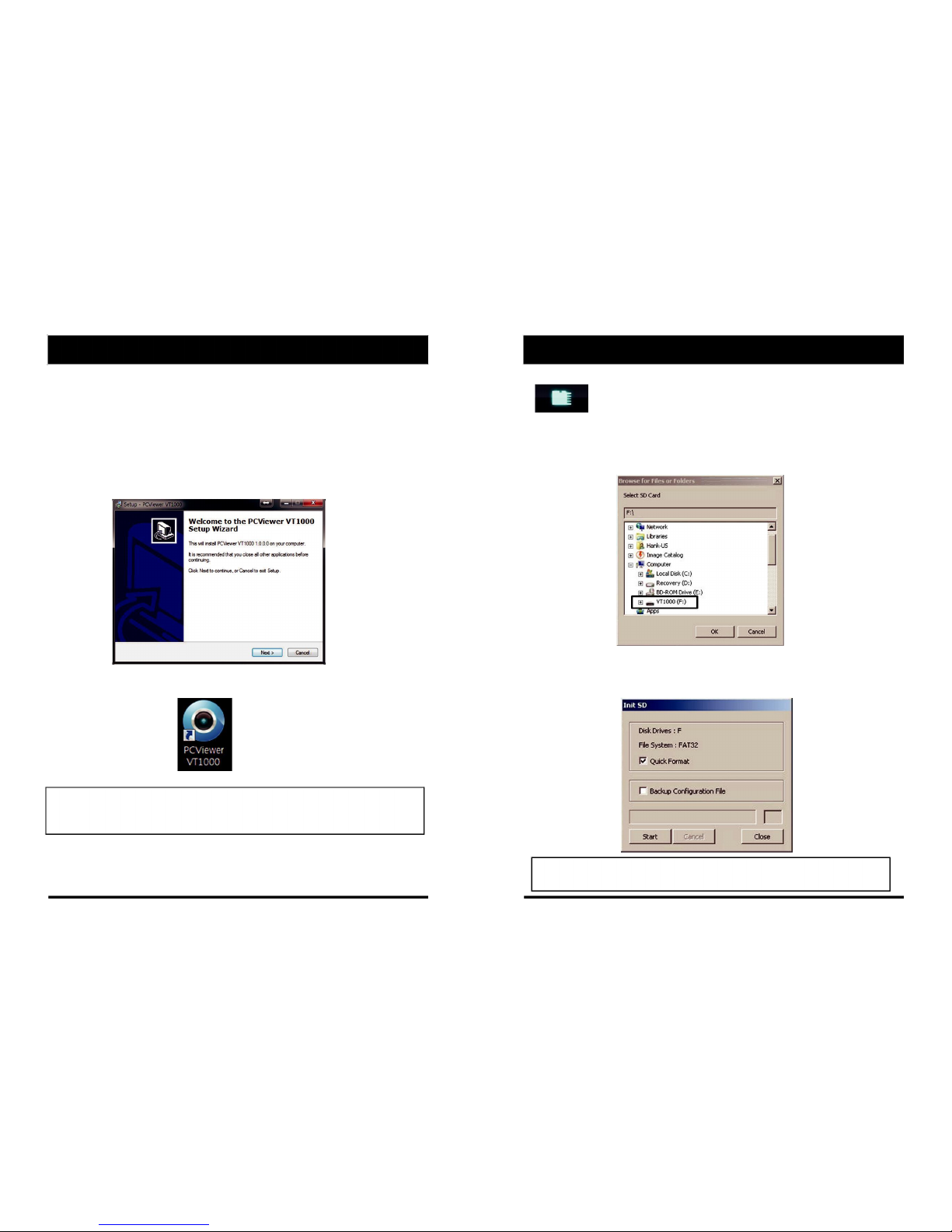
SOFTWARE INSTALLATION
The PC Viewer Software is on the provided SD card. (Also available on our
website.)
1. Connect the SD card into your PC (if your computer does not have and
SD card slot use the USB SD card reader) and open the “My Computer”
2. Right‐click the “VR1000” drive and select [Open]
3. Double click [SETUP.EXE] in the [pcsw] folder.
4. Select the language and then follow the dialog box prompts.
5. The “PC Viewer VT1000” icon will be displayed on your desktop.
NOTE: To Un‐install the PC Viewer Software
Make sure the program is not running and open the ‘Control Panel’
Select ‘Remove Program’ and remove the PC Viewer Software.
INITIALIZE SD CARD
initialize SD Card’ Icon
To initialize the SD card, click on the above icon and you will be
presented with the following screen to choose the card to initialize. Click ‘Ok’
when selected.
On the following screen, check the ‘Quick Format’ button and uncheck the
‘Backup Configuration File’ and click ‘Start’ to begin initialisation.
NOTE: The PC Viewer software will automatically be copied to [pcsw]
folder on the SD card.

13 14
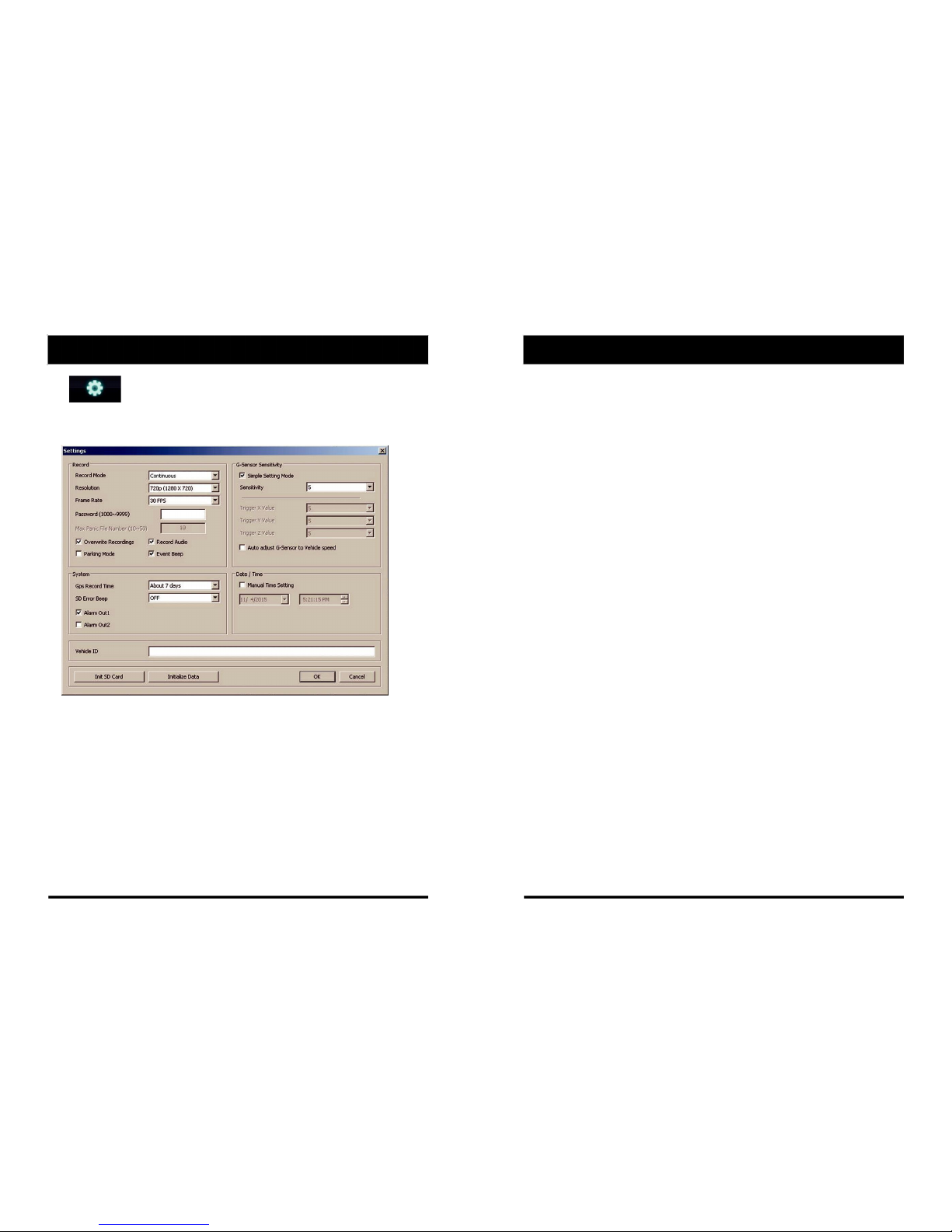
SETTINGS
[Settings] icon
This option allows you to adjust the settings on the recorder. Click the above
icon to bring up the screen below.
Record Mode
Event (Automatically starts recording by G‐sensor or Panic button.)
Continuous (Always recording when powered by DC 12/24V.)
Resolution
VGA (640x480), 720P (1280x720), 1080p HD (1920x1080).
Frame Rate
Adjust the frame rate from 30fps, 15fps, 10fps, 1fps
Password
Enter 4 numbers from 1000 to 9999 as a password
Overwrite Recordings
This function allows the unit to overwrite old files on the SD Card
automatically. You can overwrite the continuous, panic or G‐Sensor
recorded files.
Record Audio
Turn the audio recording on or off.
SETTINGS
Parking Mode
Set Record Mode as Continuous and then you can check the Parking Mode box.
If G‐Sensor value does not change for 5 minutes, the record frame rate will be
automatically change to 1FPS. When a vehicle starts to move then the parking
mode will switch off automatically and start the continuous recording
immediately
Event Beep
Turn on the event beep to make the unit ‘beep’ when the G‐sensor has been
triggered or the Panic button has been pressed.
G‐Sensor Sensitivity
The shock sensor sensitivity can be set to ‘Simple setting Mode’ or ‘Custom’. Set
to easy allows you to set the sensitivity to 9 (High), 5 (Medium) or 1 (Low).
In custom set, you can set 3 different shock sensor values individually.
Auto adjust G‐Sensor to Vehicle speed
Once it checked, SW2300 will automatically decrease the G‐Sensor sensitivity
at higher vehicle speeds to compensate for the naturally added G‐forces that
are experienced due to velocity.
GPS Record Time
Select the total log file size.
About 2days (80MB)
About 7days (280MB)
SD Error Beep
Turn on the SD Error beep to make the unit ‘beep’ when the SD Error occurred.
Alarm Out1
High voltage 5V out when G‐sensor or Panic triggered. (Low to High 2 seconds)
Alarm Out2
High voltage 5V out when SD error occurred. (Low to High 2 seconds)
Date/Time
Automatically synchronize with GPS time. However this manual time setting is
also available to use the unit at the inside of building.
Vehicle ID
Set a vehicle ID for the unit.
Init SD Card (Initialize SD Card)
All video and GPS data will be deleted and create necessary folders and copy
necessary files into the SD card.
Initialize Data
Click this option to delete all recorded files on the SD card. Please backup all data
files you wish to keep before doing this.

15 16
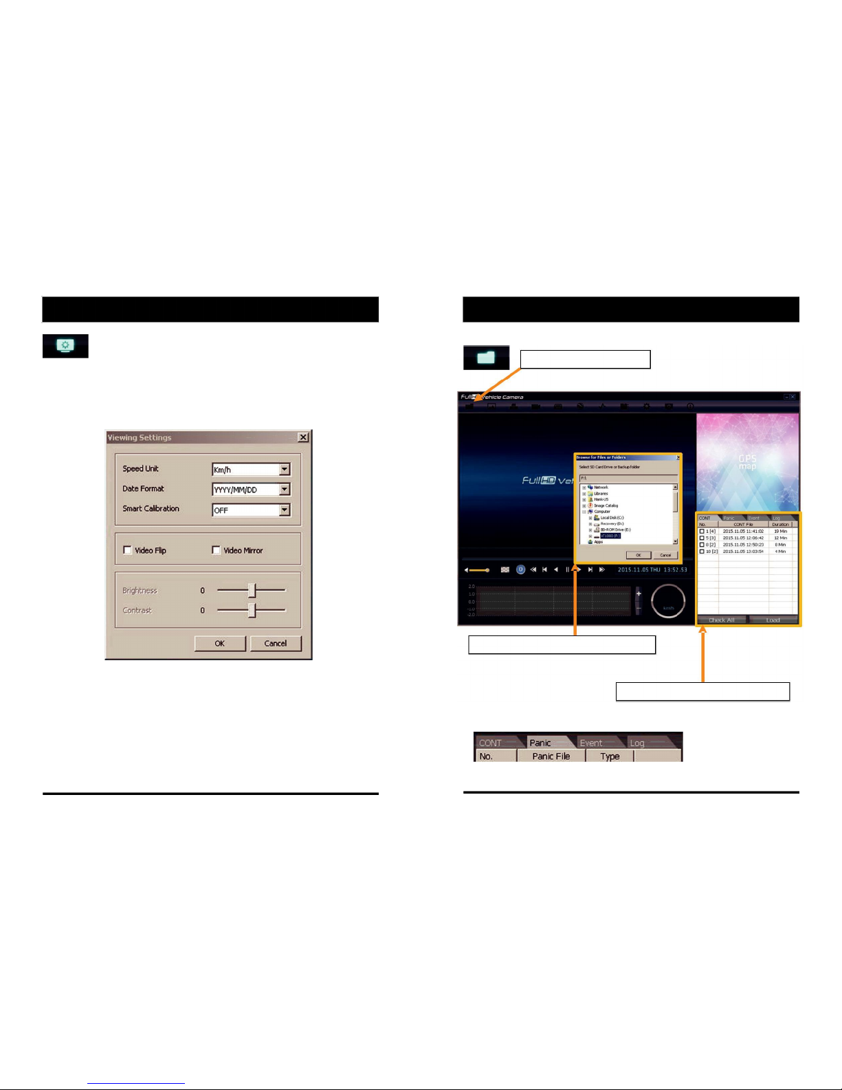
PC VIEWER SOFTWARE VIEWING SETTINGS
Viewing settings
This setting is for the PC Viewer Software itself. To set the Recorder, refer to
page 15.
The ‘speed’ unit & ‘date’ formats can be changed with this Viewing settings.
Video Flip, Video Mirror, Brightness and Contrast can be set in this Viewing
Settings
Open the SD card
Insert the SD card into your PC
① Click “Select SD Card” icon
② Select the SD card drive and click “OK”
③ Click “Check All” and then click “Load”
Change tap to load the Panic Events or G‐sensor Events or Log files.
17 18
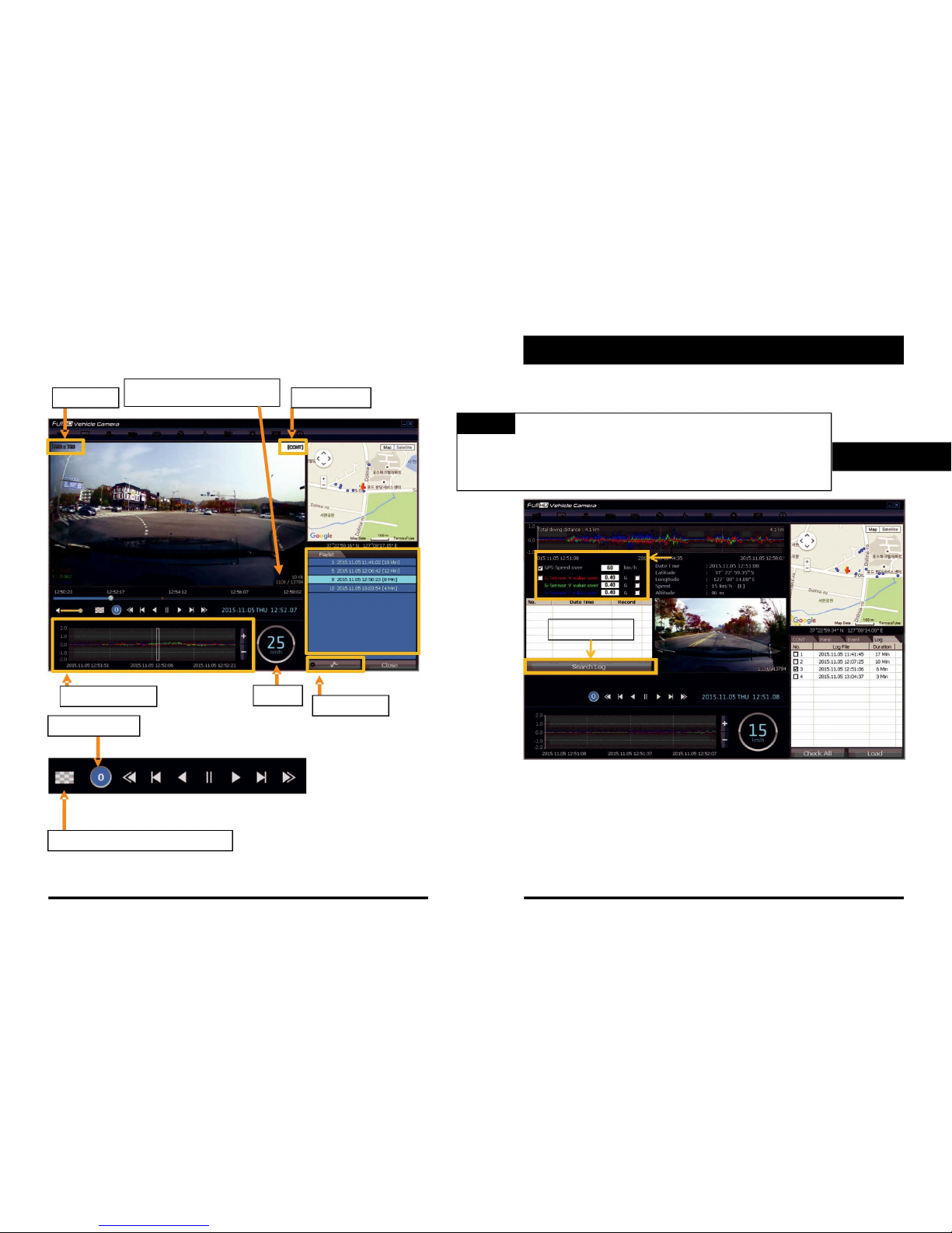
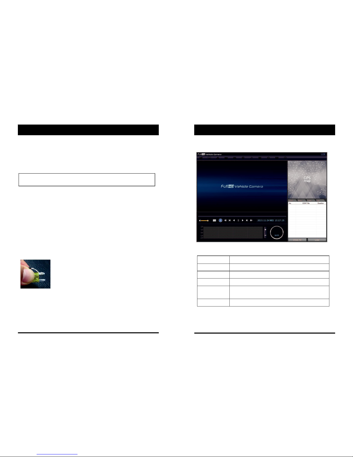
Playback
Frame Size
Resolution
Display Frame / Total frames number
Record Mode
G‐Sensor Graph
Speed
Event Search
Playback Speed
X0.5, 1
X0.5, 1
Reverse
Play
X2, 4, 8, 16
Pause
Fast Forward
X2, 4, 8, 16
Previous
Next
Fast Reverse
Image
Image
4x4 Multi View (Thumb‐nail function)
LOG FILE PLAYBACK
Select [LOG] tap.
Check the log from the log list using mouse or click [Check All]. Then click [Load].
Log data will be recorded during driving even if there are no
events. The total log data size can be set from 2 days, to 31days. The log data
overwrites the oldest data. Using this log data, you can use the data sorting
function which helps to find a specific data like more than 80mph(or 80km), for
example.
Input sorting data
Search button
GPS speed, G sensor X value, G sensor Y value, G sensor Z value,
can be checked first on the small check box at right side of each value.
Then input data for data sorting.
If there is recorded video data, [Switch] or [G Sensor] mark will be
displayed on list.
G sensor X value: Front & Back (like Quick brake or Quick Start)
G sensor Y value: Left & Right (like Quick Turn)
G sensor Z value: Up & Down
19 20
Log data
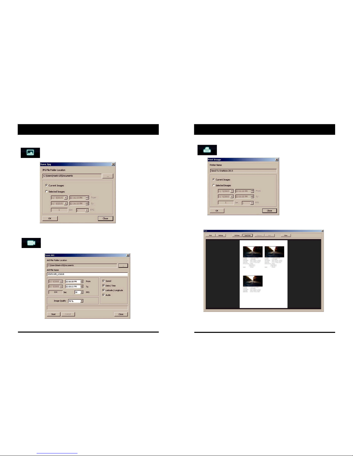
Save JPEG and AVI File
Pause the playback and click “Save JPG” icon to make JPG images.
“Save JPG” icon
Pause the playback and click “Save AVI” icon to make an AVI file.
“Save AVI” icon
Print Image
Pause the playback and click “Print Image” icon.
“Print Image” icon
Choose to print the current image or select another image from the same
file you are in by searching the time and date.
See a preview of the printed image and alter the printer settings to change
paper size/orientation etc.

21 22
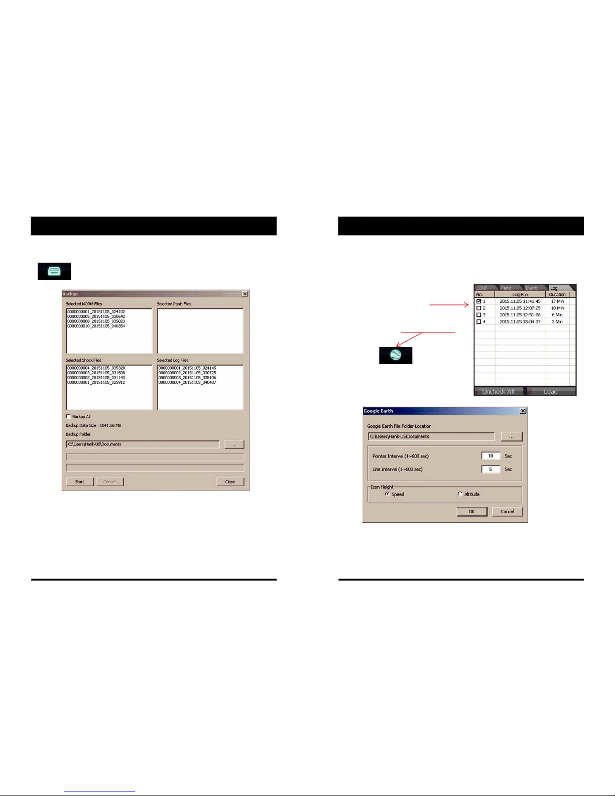
BACKING UP FILES
Select “Cont”, “Panic”. “Event”, “Log” tap and select the files first.
And then click the Backup icon to backup the files to the PC.
“Backup” icon
To backup the whole data from the SD card to the PC, check the “Backup All”
option.
GPS Log to KML Converter
To see the whole route on Google Earth, select the log file and click the Google
Earth icon, as shown below.
STEP 1. Install Google Earth on your PC. (http://www.google.com/earth/)
STEP 2. Check the log file
STEP 3. Click the Google Earth Icon
Select the folder location of the KML file.
Click “OK” and the route will then be shown on Google Earth.
We recommend you use Google Earth Version 5.0 or above.
23 24
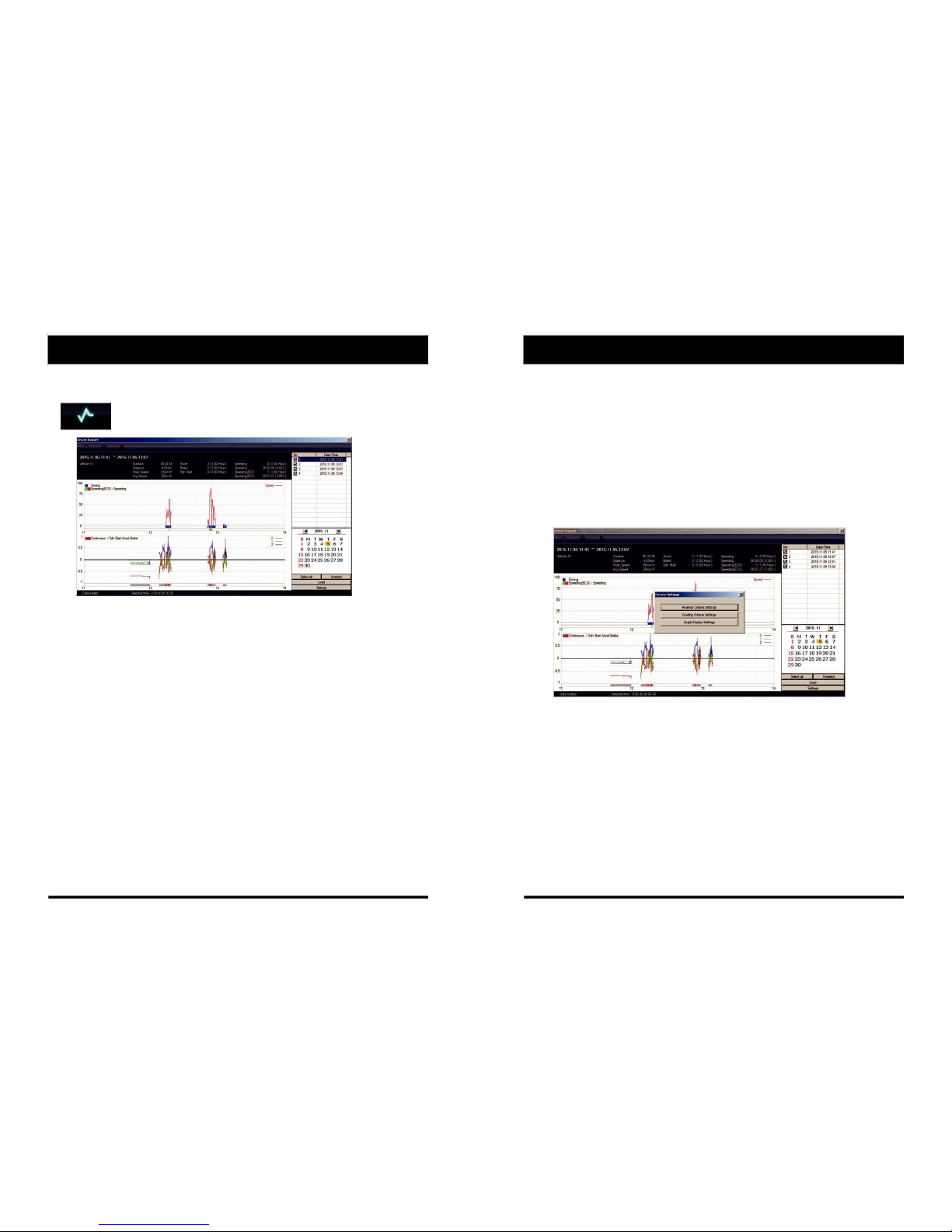
Driver Report
During the viewing, click the “Driver Report” icon to view the below Driver
Report Screen.
“Driver Report” icon
From the calendar in the bottom right corner, choose the date you wish to inspect
among the dates highlighted in blue. Dates that are not highlighted in blue, do not
have the relevant data.
All data from the selected date will be automatically chosen from the
selection on the right. You can unselect data that you do not need. When data
is selected, click the ‘Load’ button to load the data.
A summary of information can be found on the top of the window including;
vehicle ID, user ID, total duration and total distance. In addition you can analyze
the number of over‐accelerations, over‐decelerations, sharp turns, over‐
speeding, over‐RPMs that exceeded the pre‐set limit.
Top Graph
The top graph shows the speed (red) and below are three indicator bars that
show driving patterns. The first bar shows driving (blue) and idling (grey) and
the second bar shows the speed.
White means that the vehicle was within both the permitted speed and eco‐speed
limit, green means above eco‐speed but within permitted speed limit, and red means
above the legal speed limit. The last bar shows the state of the engine where white
means the engine is off, blue means it is running properly within the pre‐set RPM limit,
and red means over acceleration, i.e. exceeding the pre‐set RPM limit.
Analysis Criteria Settings
Bottom Graph
The lower graph shows the G‐sensors. The x‐axis is in red, y‐axis in blue, and
z‐axis is green.
The indicator bar below shows jolts in the G‐sensor values, i.e. G‐sensor
values that exceed the pre‐set limit. Grey means normal conditions, red
means jolts in the x‐axis direction, blue in the y‐axis direction, and green in
the z‐axis direction.
Configurations for this function can be set by clicking the [Setting] button in
the right bottom corner. The limits for G‐sensor, permitted speeding,
excessive RPM, and eco‐speeding can be set under the ‘Analysis’ tab and
ranges for the two graphs can be set under the ‘Component’ tab.
Table of contents


