SILENTRON 4001 Centrale Sil-Bus 4A User manual

1
REGULATION COMPLIANT CONTROL PANELS
EN 50131-1 ; 50131 A1/IS1; 50131-3; 50131-6; 50136-1; 50136-2
GRADE II - CLASS II - ATS: SP2/DP2 (with GSM inside)
Instruction manual 2001-3EN-GD160802GM
Control panel firmware version from 3790J02A and following versions (touch screen keypad from 3720J01A and following versions).
All products versions can be upgraded using the PC and special software
CONTENTS OF THE FIRST SECTION –USER AND INSTALLER MANUAL
1) FOREWORD Current regulations and their application –Certified System –Silentron FW 2
2) FEATURES Overview and differences between the two control panel models 2
Figure of the two control panel models –Diagram of IMQ compliant system 3
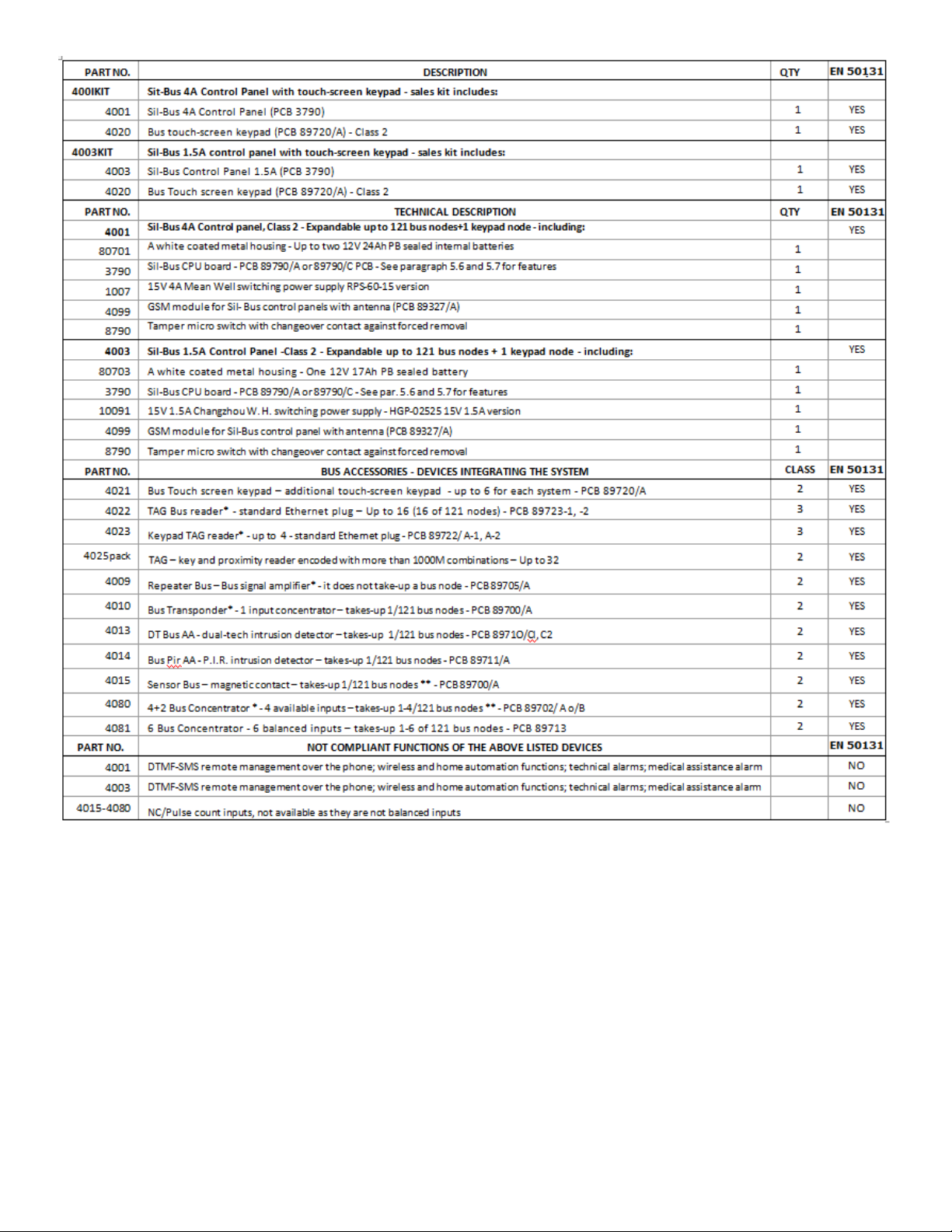
Table of IMQ certified products and accessories 4
Hardwired devices –Installer responsibility and performance–System designing –Audio Wizard 4
Minimum system requirements 4
3) USER MANUAL Table - User access during standard conditions 5
User codes and user access levels –Meaning of icons –Master and Slave codes 6
Changing codes - arming –test - Time/data and display settings 6
Temporary detector exclusion - Display event history 6
Access and event history log display –Entry/Exit delay - Disarming - Tag readers and applications 7
Disarming under duress –Direct and home automation controls 8
User access with events table 8
Remote control panel management over the telephone 8
Remote audio monitoring –Editing phone book –Alarm modes: intrusion and other modes 9
System protection 10
4) ALARM CALLS Outside calls 10
5) SPECIAL FUNCTIONS (not compliant) Home automation controls - Audio alerts - Access control - TTL connections TTL 10
6) USER INFORMATION Alarm systems overview 10
7) INSTALLATION MANUAL Upgrading control panels –Firmware version –Opening and mounting 11
Sistem's protection features –230V connections and batteries 11
Electronics logic board (HW) 11
Power supply and batteries - current availability - Electric connections table 12
Hardwired balanced lines (not bus) –Bus cable sizing and safety 13
End of line resistors –Bus repeater 13
8) Touch-screen keypad Setting and addressing Bus elements 13
Built-in telephone transmitter - Features –Settings 14
Initialing operation –Addressing Bus elements 15
Table of installer access during operations 15
9) TOOLS menu Setting user code –Tag –Bus modules –Bus modules parameters 16
Modules' settings table 17
Detectors "AND" function 18
Setting multi-purpose Bus modules –Slave Touch-screen –Bus relay boards 18
Bus TAG readers 19
Adjusting Bus detectors –Managing hardwired inputs –Replacing Bus modules 19
10) SETTINGS menu System's parameters –Time functions 20
Scheduling weekly arming/disarming 21
Scheduling weekly home automation functions 21
SIM card management–Built-in relay–Excluding detectors–GSM/PSTN priority–Utility functions 21
11) MESSAGES menu Audio messages 21
SMS/SMT (technical) text messages 21
12) PHONE BOOK menu Setting phone numbers 22
13) DIGITAL MESSAGES Setting calls to the central monitoring station 22
Dual phone lines: setting calls to the central monitoring station 22
14) SETUP OVER THE PC Local and remote management 23
Connecting, configuring and managing the system from a local PC 23
Reading and writing data –Parameters of peripheral devices –Control panel's technical sheet 24
15) REMOTE MANAGEMENT Connecting, configuring and managing from a local PC-Remote management over GMTS 25
16) MULTI USER SYSTEMS Available configurations 25
17) MAINTENANCE Control panel maintenance instructions 26
18) APPENDIX EC conformity declaration –Applied regulations
SILENTRON FIRMWARE Variations supplied by Silentron Firmware 27-31
DIGITAL PROTOCOLS CODES TABLE 32

2
1 FOREWORD - CURRENT REGULATIONS AND THEIR APPLICATION (legal notes supplied by the manufacturer)
1.1 Laws and Regulations
These control panels must be installed in compliance with the local Laws.
1.2 IMQ Italian Certification - SECURITY SYSTEMS - EN 50131 . . . .
Compliance is achieved when all components have been certified. The system’s grade corresponds to the system component/components with lower grade.
1.3 INCERT certification of these control panels
This certification prevides the EN 50131 conformity and some caracteristics for Belgium only. To activate this FW it needs to entry in the right menu (see diagrams par. 8.4 and 10.6) to
confirm the choice. The control panel will function as here is described.
If used with the firmware automatically offered and within the limits and/or the instructions outlined for each application, these control panels fully comply with standards EN 50131-1;
50131 A1/IS1; 50131-3:2009; 50131-6:2008; 50136-2-1. Any adjustments and/or configurations must be performed within the specified limits.
1.4 SILENTRON firmware
In compliance with general regulation criteria, this firmware allows to perform operations with are not consistent with the aforementioned regulations. These operations are therefore not
compliant. Main not compliant operations are: 1) external detectors’ differentiated alarm management, which the standard does not mention 2) immediate alarm transmission dynamics,
the standard requires that it be delayed, 3) immediate display of alarm location during partial arming and therefore with user on the premises, which is not accepted by the standard. The
other operating differences are specified in the paragraphs pertaining to each topic.
IMQ certification will be void when this other firmware is selected. Installer and user are responsible for firmware selection. The manufacturer is available to maintain that some of the
operational decisions envisaged by its firmware improve user’s safety and usability.
1.4.1 Silentron firmware selection
The control panels are developed with the IMQ firmware and you must enter the appropriate menu (see Figure at paragraph 8.4 and paragraph 10.6) to change firmware. Please refer to the
specific Silentron Sil Bus manual should you wish to replace the firmware even though all of the programmed settings will be maintained.
2 OVERVIEW
Sil Bus control panels are devices that allow to manage and control alarm and home automation systems. They are formed by two modules which make up a "kit":
a) the control panel, enclosed in a metal, which houses also the power supply and the electronic control board as well as an optional GSM network board.
b) a black and white touch-screen user interface which must be connected to the control panel through a proprietary serial line (Bus) which is an integral part of the unit.
Various accessory devices may be connected to the control panels using a 4 way serial cable (Bus –see cable features). These devices are used to handle the control panel, detect various
kinds of events and generate various types of warning and/or deterring alarms. Devices that convert hardwired ones to wireless ones (not certified) are also available to make use of the full
Silentron wireless range along with home automation actuator boards.
The control panels are supplied with outputs for analogue operations and may be hardwired using conventional connections.
2.1 DIFFERENCES BETWEEN THE TWO CONTROL PANELS
Sil-Bus are extremely powerful control panels that may be used to develop small and large systems using from 1 to over 120 detectors. You can select one of the two available control panel
models based on the type and size of the system to be installed. The two models differ only for the control panel’s housing a nd its power supply which allows for a different number and type
of batteries (see figures) as well as different type and number of powered devices (see electric energy consumption table).
The specifications supplied in paragraph 7.4 must be taken into account because the different power supply and the resulting different installable batteries are clearly appropriate for
different sized systems.
3
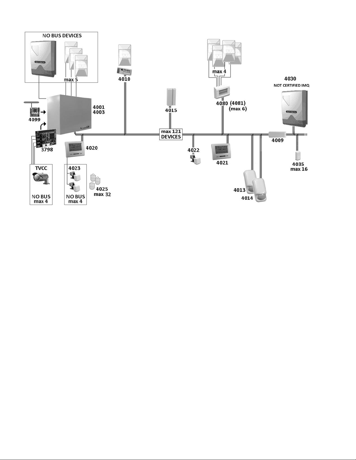
2.2 EXAMPLE OF A FULLY EXPANDED CERTIFIED SYSTEM
2.3 CERTIFIED SILENTRON PRODUCTS
Please find following a table listing IMQ certified products. This table also lists the main components of the control panels and th e special installation requirements of some components.
To show other compatibles devices, that are not EN 50131 certified, please see al page 27.
2.4 CONVENTIONAL HARDWIRED PERIPHERAL DEVICES
Control panels are fitted with lines that are not Bus to which you can connect:
Up to 5 detectors powered over 3 wire balanced line
no. 1 (or more) self-powered siren with built-in battery
no. 1 (or more) not self-powered built in siren
no. One 12V microphone for remote audio monitoring
no. 1 Management Card for 1-4 hardwired CCTV cameras (not certified accessory device)
Caution! The NOT BUS devices that comprise the system (alarm intrusion devices –those supplied by other manufacturers) must feature at least a Grade 2 certification in order not to
downgrade the overall system. The 4099 GSM module is certified as part of the overall system Cameras control board part no. 3798 is not part of the provisions foreseen by the EN 50131-1
standard and its following amendments.
2.5 INSTALLER’S RESPONSIBILITY & PERFORMANCE
Each alarm system consists of several peripheral devices, detectors, sirens, control points, keyboards, etc. which are controlled by one of the control panels that are featured in this manual.
This manual describes all of the panels features, their use and their operation. A professional installer has the essential task of identifying which functions are required by the customer, to
foresee the safety measures required by the system and to install the system with diligence and professionalism. The installer must integrate the instructions supplied in this manual with the
operating variables being implemented in the system in order to allow the user to fully master all of these functions.
2.5.1 INSTALLER AND USER AUDIO WIZARD
In order to facilitate the system’s implementation and use, these control panels feature an audio wizard that illustrates the available operations during their use. For this reason some
marginal and/or highly intuitive aspects of the control panels may not be mentioned in this manual. Control panels have been designed in such a way that no user operation could damage
the system.
2.5.2 MINIMUM SYSTEM REQUIREMENTS FOR EN 50131-1 AND FOLLOWING STANDARD COMPLIANCE
The system must foresee at least one control panel battery, a keypad with enabled built-in telephone dialer, a detector and an external siren (Grade 2 certified).
4
* Devices must be installed with tamper protection in order to comply with the standard.
** Terminal board’s NC not balanced inputs are not compliant and therefore not available.
5
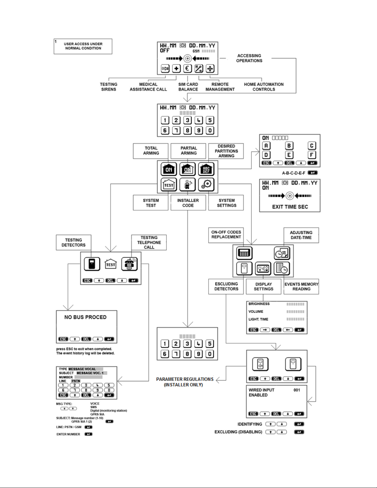
3 USER MANUAL : The following figures describe all of the operations that the user can perform on the control panel using tactile keypad part no. 4020. The figures specifically describe how
to partially and fully arm the system, how to test it and the user settings.
6
3.1 ACCESS CODES - Caution! Keypad locks for 3 minutes when the wrong code is entered more than 5 times!
You must use 2 access codes, the USER code and INSTALLER code, in order to operate the control panel.
These different codes are programmed by the installer during the installation. After the installation, the user must change the temporary user code programmed by the installer to have full
system’s ownership. Any future changes made by the installer will need to be authorized by the user employing this new user code.
3.2 ACCESS LEVELS
Level 1: Control panel can be accessed by all: anyone can see the display’s basic screen
Level 2: User Access: user can access control panel by entering a MASTER user code (5 digits) or a SLAVE user code (see par. 3.4.2)
Level 3: Maintenance access: control panel's settings can be accessed only by entering the installer code
Level 4: Manufacturer access: control panel’s upgrading operations may be performed only when the control panel is disabled.
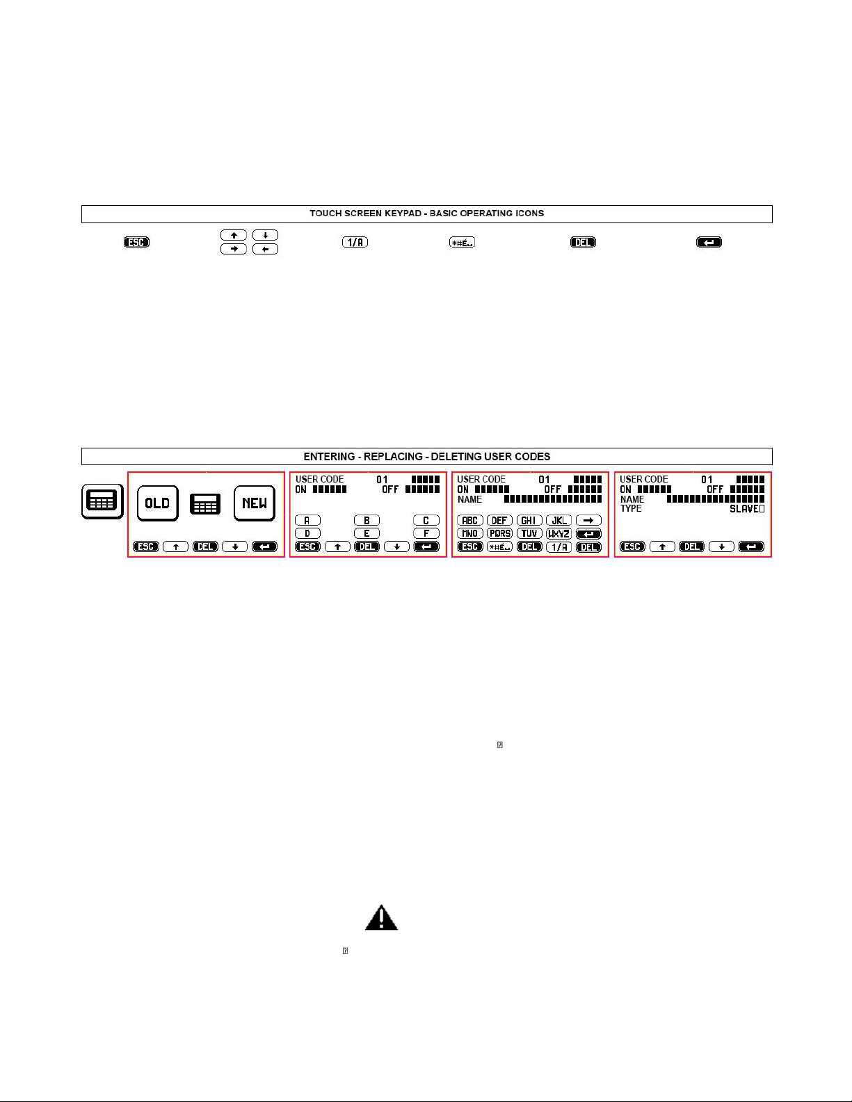
3.3 MEANING OF ICONS
ESCAPE: exit screen
without saving any
changes
move inside a screen or
exit writing mode
switch keypad operations
from letters to numbers
special characters
delete any changes that
have been made without
saving
confirm entered data
ALWAYS SELECT
AFTER HAVING MADE
ANY CHANGES
---------------------------------------------------------------------------------------------------------------------------------------------------------------------------
3.4 USER ACCESS DURING STANDARD CONDITIONS (only MASTER codes - see table 1)
TIME/DATE-DISPLAY: apply pressure to the center of the display and enter user code to access: fully arming mode, default partial arming mode (to arm zones previously set during system
installation) and selectable partial arming mode. The decreasing exit time (entry/exit delay after which control panel is armed) will display after selected arming procedure has been
performed.
TEST: use to test system’s components, beginning with the Bus network. Follow the instructions on the display.
INSTALLER ACCESS: used to enter installer code and to service control panel.
3.4.1 SETTINGS: some operations, such as setting the control panel’s clock or setting the display, are intuitive and simply require that you follow the text and audio prompts. Please find
following a description of the other operating procedures:
3.4.2 REPLACING/CREATING USER CODE (up to 32) –please see par. 9.1 - 9.1.1 and above figure.
The USER code, which allows you to access the control panel, may be MASTER or SLAVE. You are enabled to perform all of the procedures described in the User Access Tables when you use
the MASTER code. The SLAVE code gives you access only to the previously enabled zones.
After installation is complete, user may access the control panel with the user code set by the installer to change it so that it is not known even to the installer. You can also add and/or
delete other third party codes, restricting operations to specific zones where they are necessary (e.g. A + B + C arming, A + B disarming - any possible combination of the above The user will
authorize installer’s access for servicing by entering his user code.
3.4.3 ISOLATING (EXCLUDING) a detector (only with MASTER codes). When necessary, in the event of failure for example, one or more detectors may be excluded. Please see the following
table for the relevant instructions.
INCERT - Detectors' isolating : the installer only, with his code, can isolate one or more detectors when it's necessary. The operation will be signalized by the vocal message 2 (please, register
as "Periferic device isolation") and SMS 2 (automatic text inside).
3.4.4 DISPLAYING EVENT HISTORY LOG (only with MASTER or INSTALLER codes - see also table at par. 8)
Press the event history log icon to displays the control panel’s last 500 events. Events are displayed showing (↓ ) event’s date and the device that triggered the event. Voice calls and SMS
messages are displayed as follows:
VOICE CALL . (type of message) 1-10 ; (result) OK/NO/OCC (busy) –Dialed number –Name. Examples:
VOICE CALL . 1 OK 333444555 Gianni SMS TRANS. - 1 OK 333444555 Gianni
VOICE CALL .[RESULT] –[TYPE] - PH NO. COMISSIONING –LABEL
DETEC. ESCL. –bathroom OPEN WINDOW/DOOR –main entrance
START Firmaware (reboot after a total disconnection) Upgrade firmware (reboot when a new FW is placed)
3.4.5 ARMING WITH USER CODE (with both Master and Slave codes - see table 1)
Enter the user code and press the relevant icon to fully or partially arm the control panel. Partial arming zones are set during system’s installation. Press SELECTABLE ARMING to arm
different zones, then select items to be armed. You can also set an arming delay time as well as conditions where partial arming is blocked - see par. 3.5.1.
3.4.6 AUTOMATIC ARMING: see par 10.1.2 when automatic arming has been set during installation.
3.5 USER ACCESS WITH NEW EVENTS (only with MASTER codes - see Table 2).
The "warning" icon displays when new events to be verified have occurred. The different type of events (alarm, masking, tampering, failure, etc.) are clearly described for the user to read.
Events that are no longer taking place are deleted when the user confirms that same have been read. Events that are still occurring will not be deleted.
INCERT - Tamper Alarm: the installer only, with his code, can force the arming and/or replace the system.

7

8
3.5.1 ARMING DELAY - Caution: in the following circumstances, control panels may not arm!
An arming delay ranging from 1 to 99 seconds is set during the installation. During this preset time the control panels check the system’s condition and a “warming” icon will display if any
detector has triggered an alarm. Should an alarm have occurred, you will need to read the event from the even history log after having entered the appropriate code. You can force control
panel’s arming by confirming this option ( ) in which case all detectors that are not alarmed will be enabled.
Arming is denied and the condition is displayed on the keypad if one or more detectors are alarmed during arming delay.
Caution! We therefore recommend that you wait for the system to successfully arm before leaving the premises.
Caution! Forced arming may be performed only using the keypad and only by entering the MASTER code. When arming is blocked, you must remove the cause of the blocking before you can
arm the system again.
3.5.2 DISARMING
You must enter the user code to disarm the control panels. Any occurring alarms will end when the system is disarmed. Check any new occurring events.
If any detector has been set with an alarm delay (adjustable from 1 to 45 sec.), same will trigger an alarm unless the control panel is disarmed in the meantime. An immediate alarm will take
place when a detector with an alarm delay detects a movement and a second detector without an alarm delay is also triggered. In this case, telephone transmissions will begin after 30
seconds or, when set for a longer time, after entry/exit delay time.
3.6 TAG ARMING/DISARMING
Control panels can also be controlled by a small electromagnetic key, called a TAG. Each TAG is supplied with more than 1000 million code combinations and operates by simply bring it close
to the reader. 4020 and 4021 keypads feature a built-in reader which is located on the top right hand side. This reader is pulse operated and each reading either arms or disarms the control
panel. The keypad reader does not supply any other function other than arming or disarming.
3.6.1 OPTIONAL TAG READERS
The system may foresee additional TAG readers (part no. 4022 which is bus operated or part no. 4023 which is hardwired to the keypad) whose sensitive element is located in the front
section (see relevant instructions). The above readers supply the following functions:
ON - full arming: bring the TAG close to the reader and remove it as soon as the red LED indicator turns on.
ON/P - partial arming: bring the TAG close to the reader and remove it as soon as the red LED indicator begins to flash.
OFF - disarming: when the control panel is armed, bringing the TAG close to the reader and hold it there until the green LED indicator turns on.
Yellow LED: these readers feature a yellow LED indicator. If the yellow LED indicator flashes when the system is being armed (ON - ON/P) it reports that there are open windows/doors
and/or alarm events taking place. In this case, close the open windows or try to force arming using the keypad. If the LED flashes after disarming, it means that an alarm has occurred during
arming period and that you must therefore display the event history log.
Caution! Red, green and yellow LED indicators can be programmed to stay on or to switch off after 30 seconds in order not to display system’s condition. The LEDs will turn on again when
you bring an enabled TAG near them if they are setup to switch off.
3.6.2 DISARMING UNDER THREAT - DURESS ALARM
TAG reader can be programmed to require that USER code is also entered on the keypad within 30 seconds from disarming. With this setup, the system will continue to be disarmed even
when the code not be entered within 30 seconds, but the control panel will send a preset ROBBERY message over the phone line enabling a silent alarm. This feature is useful if you run the
risk of being forced to disarm the system against your will.
3.7 SPEED DIAL COMANDS NOT REQUIRING CODE ENTRY (see Tables 1 and 2)
The user can enable these functions for different needs by simply pressing the relevant keypad icon.
Caution! Functions 3.7.1/2/4/5 are not IMQ compliant.
3.7.1 TESTING SIREN: press once to enable sirens, press again to disable them. This function can also be used as a neighborhood alert. Sirens will be silenced automatically after the preset
time when they are not previously manually turned off.
3.7.2 MEDICAL ASSISTANCE: press and hold icon for 2 seconds to enable preset emergency telephone calls.
3.7.3 SIM BALANCE: press and hold icon for 2 seconds to enable the call to request SIM remaining balance to SIM provider.
3.7.4 REMOTE MANAGEMENT: press and hold icon for 2 seconds to enable electronic connection with the installer (if foreseen).
3.7.5 HOME AUTOMATION FUNCTIONS (controlling electric charges):
Control panels can be used to control any type of electric device (automations, lights, engines, etc.), through the built-in relay or the keypad using the appropriate boards part no. 4035 Relay
Bus and by confirming operation. The installer must clearly describe the functions that are shown on the display since these vary greatly from one installation to the other.
Commands are simple to use and can be performed in different ways using:
the system’s touch-screen keypads that display which controls to execute. Identify the actuator by making
phone calls followed by number combinations corresponding to the required commands (see par. 3.8.1)
especially written SMS messages (previously stored to be retrieved using the phone –see par. 3.8.2)
specific APP downloadable from website www.silentron.com and programmable on the user’s SMART PHONE.
3.8 REMOTE REQUESTS AND CONTROLS - Caution! The functions described in this paragraph are not IMQ compliant as same are not foreseen by the standard.
3.8.1 Accessing the control panel using the landline (PSTN) number –Only with audio wizard message recording.
Dial the number - wait for two rings - hang up - dial the number again within 1 minute. The control panel answers using the audio wizard message recording followed by a beep. Dial the
USER code followed by # to open the connection with the control panel. Continue as follows:
3.8.1.1 Sending commands the control panel. Press the following keys to send the corresponding command to the panel: it will reply with an audio message.
check control panel's ON-OFF condition 0 # arm control panel 0 * 1 #
arm only A+B zones 0 * 2 # disarm control panel 0 * 0 #
INCERT - Note ! The remote arming/disarming will be confirmed by 3 beeps/arming and 1beep/disarming to the first number on the phone book.
3.8.1.2 Sending commands to the control panel’s relay. Press the following keys the send the corresponding command. The control panel will reply with one or more beeps
check relay status 20 # relay is enabled = 3 beeps - relay is disabled = 1 beep
enable relay 20 *1 # 3 beep
disable relay 20 *0 # 1 beep

9
3.8.2 Accessing the control panel using the mobile network (GSM)
The numbers stored in the control panel’s address book by the installer can be programmed allowing their direct access or not as long as the dialing number is not anonymous.
a) Making a call from a number that is recognized and enabled for direct access. Dial control panel’s SIM card number, the control panel answers using the audio wizard message recording
(when same has been recorded) followed by a beep or by an immediate beep. You are connected to the control panel and can perform the following described operations once you hear this
beep.
b) Making a call from a number that is not enabled for direct access. Dial control panel’s SIM card number, listen to audio wizard message recording (when same has been recorded)
followed by a beep. Enter the USER code followed by # after hearing the beep. You are now connected to the control panel and can perform the required operations.
Operations. Press the same key combinations used when calling from a PSTN line (see above) to check control panel and to perform operations.
INCERT - Note ! The remote arming/disarming will be confirmed by 3 beeps/arming and 1beep/disarming to the first number on the phone book.
3.8.3 SENDING COMMANDS VIA SMS (only when calling from a number enabled for a direct access)
You can control the control panel using SMS messages. The control panel may not receive these commands immediately since same are subject to the SIM card's provider transmission
service. Caution! ײַ= space
3.8.3.1 Controlling the control panel via SMS
operation SMS text to send control panel's SMS reply
check control panel's ON-OFF condition C? ON ײַOK ON ײַACF(zones) ײַOK OFF ײַOK
fully arm control panel ON ON ײַOK
partially arm zones ON ײַACF(zones) ON ײַACF(zones) ײַOK
disarm control panel OFF OFF ײַOK
read event history log MEM? last 3 events displayed in the event history log
request SIM card balance ? € according to SIM card's provider mode
INCERT - Note ! The remote arming/disarming will be confirmed by 3 beeps/arming and 1beep/disarming to the first number on the phone book.
3.8.3.2 Controlling control panel's built-in relay
operation SMS text to send control panel's SMS reply
check R? R ײַON (OFF)
enable R ײַON R ײַON ײַOK
disable R ײַOFF R ײַOFF ײַOK
3.8.4 Controlling system's Bus relay boards 4035
These boards can be managed only through the touch screen keypad (see par. 3.7.5) or via SMS (if GSM module has been installed). For easier operations, you can use APP icons that replace
sending SMS messages.
Caution! You must transmit the number of the Bus node corresponding to the setup relay board (for example:32).
operation SMS text to send control panel's SMS reply
manage 32? 32 ײַON (OFF)
enable 32 ײַON 32 ײַON ײַOK
disable 32 ײַOFF 32 ײַOFF ײַOK
3.8.5 REMOTE AUDIO MONITORING
Install and connect to the control panel a remote microphone to perform remote audio monitoring. Press during a phone call to hear what is happening where the microphone has been
installed. Two way conversations are not possible.
3.8.6 EDITING PHONE NUMBERS IN THE CONTROL PANEL'S PHONE BOOK
Edit one or more phone numbers stored in the control panel's phone book by sending the following SMS message: A old number A new number (without any spaces in between). Reply:
number HAS BEEN CHANGED
3.9 ALARM MODES
Once enabled, the control panels are always operational to assure tamper protection. You can temporarily disable tamper protection only by enabling TEST mode. Enter the INSTALLER code
to enable TEST mode (maintenance - see. par. 19). Enabling TEST mode by entering the USER code does not disable tamper protection functions.
Operating modes: intrusion alarm zones
a) Disarmed control panel OFF only 24 hour zones, direct and automation controls are enabled
b) Partially armed control panel ON/P also armed intrusion alarm zones are enabled
c) Fully armed control panel ON all zones are enabled
3.9.1 ALARM MODE, REPORT AND MANAGEMENT
The keypad does not display any alerts during fully armed or partially armed mode. The event history log icon prompting to check the log can instead display when the control panel is
disarmed or during disarmed mode (see par. 3.5).
The foreseen alarm devices, telephone calls/preset text messages are activated when an alarm event takes place. Disarming the control panel stops any alarm and/or telephone call, apart
from digital ones to the central monitoring station which cannot be blocked until the end of the cycle (contact central monitoring station’s staff if alarm is triggered by mistake).
Warning! Telephone messages are sent only if they have been properly enabled, assigned and recorded or written (Installation).
3.9.2 INTRUSION ALARM FUNCTIONS
Foreword: all detectors and alarm delayed detectors in the system can be set with a 1 to 99 seconds arming delay. Alarm delayed detectors will trigger an alarm after the time set during
installation (adjustable from 1 to 45 seconds). Arming delay allows user’s entry/exit when the keypad is installed in a protected zone within the premises. The following alarm modes take
place when the system is fully or partially armed.
3.9.2.1 IMMEDIATE ALARM: alarm devices (sirens and/or other) and text/audio alarm phone messages are activated when a detector set for an immediate alarm is triggered. The alarm lasts
for an adjustable time (from 1 to 999 seconds) and can be repeated over time if a new event is triggered by a detector.
3.9.2.2 DELAYED ALARM: the alarm delay time count down begins when a detector set for a delayed alarm is triggered. The alarm will activate at the end of the delay time unless the control
panel is not previously disarmed. Telephone messages are sent only at the end of delay time when delayed alarms are triggered. See 3.5.2.
3.9.3 TECHNICAL ALARM FUNCTION - Not EN 50131 compliant
A technical alarm is triggered by smoke, gas, flooding detectors when these events take place in the setup zones. These detectors are always enabled, regardless the control panel's
condition. This alarm only displays a "warning" alert during disarmed mode.
Caution! Alarm disabled! Every detector is automatically excluded after 3 alarms have occurred during a continued period in which the control panel is fully armed or partially armed. A
disabled detector is reset when the control panel is armed again.

10
3.9.4 PROTECTION FUNCTIONS OF THE SYSTEM
TAMPER: this function constantly monitors all of the system's components and its hardwired lines reporting any sabotaging attempts. All visual, audio and communication devices are
activated triggering a general alarm when tamper takes place and the control panel is armed . The "warning" icon displays and telephone calls are dialed without any other audio alarm
taking place when the control panel is disarmed.
MASKING: the masking protection function is supplied by any anti-masking detectors that may have been connected to the Bus. All visual, audio and communication devices are activated
triggering a general alarm when masking takes place and the control panel is armed. The "warning" icon displays without any other audio alarm taking place when the control panel is
disarmed.
INCERT - Caution ! The reset of anti-tamper/masking alarms will be possible by the installer only
BUS FAULT: this function constantly monitors the Bus line to which all of the system's components are connected. When the control pane l is armed any detected bus faults trigger a cycle of
telephone calls without activating any audio alarm.
TELEPHONE FAULT
PSTN line: the landline is constantly monitored. When the system detects that there is not line or that a fault has occurred for more than 10 seconds, this is displayed on the keypad
and reported via GSM (if available).
GSM line: when the GSM board in installed, any fault on the GSM line is displayed and reported after 15 minutes using the PSTN landline. When line is reset, the system sends SMS
messages confirming GSM's availability.
SUPERVISION CALLS: the control panels call and transmit monitoring messages every 1-25 hours (adjustable).
The first number stored in the control panel’s phone book will be dialed to send a 3 second beep when the PSTN line is the only operating one. When also the GSM line is operational, preset
no. 5 SMT will be sent to the preset phone numbers stored in the phone book.
230V POWER FAILURE/POWER RESTORED: any power failure is displayed after 10 seconds. If failure persists for more that preset time (adjustable from 1 to 60 min.), telephone calls will be
made and SMS will be sent. The system immediately reports when 230V power is restored.
LOW BATTERY: batteries are monitored only when there is not power available. Low battery visual/audio alerts are displayed on the keypad and audio/SMS messages are enabled after 10
seconds. The system reports a low battery level when battery is below 10.9V. Battery level is restored with a 11.2V charge. Temporarily disconnect the control unit from the power line to
check battery level.
OPEN WINDOW/DOOR: the system reports any passage that has been left open. These events are logged in the event history log and can be displayed after having entered the USER code.
Open windows/doors prevent control panel from being armed. You must force arming or close windows/doors that have been left often in order to arm the system.
4. ALARM MESSAGES SENT BY THE CONTROL PANEL : acknowledgement pass-trough
During an alarm the control panel will call all the numbers has been stored in the phone book and jointed to the alarm event, as described above.
Caution ! The called user must confirm the reception by pressing a number on his phone. Without this confirm, the call will be stored as "unreceived" on the panel memory.
Digital message to the central monitoring station: this message has priority over any other transmission. Completing
this function may take a few minutes, as long as it takes for the surveillance staff to reply.
Caution! This is the only type of message that is not disabled by disarming the control panel.
SMS messages: alarm SMS are sent by the control panel when the GSM module is available. SMS message transmission is stopped when the control panel is disarmed.
Audio messages: the control panels dial every setup phone number in sequence and transmit an audio message. When both GSM and PSTN landline are available, you will select which
line has priority during system's setup. If a number does not reply or is busy or without reception confirm, each number is dialed up to three times after the first sequence of calls has
been completed. The control panel will stop dialing when it is disarmed, but the digital calls to Security cannot be stopped.
Disabling calls remotely: press # after having heard the “end of message” beep to disable additional calls.
5. NOT EN 50131 COMPLIANT SPECIAL FUNCTIONS
Control panels supply some complementary functions which may be useful to the user based on the individual system.
5.1 Detectors and Bus relay board 4035 (CHIMES - HOME AUTOMATION FUNCTIONS)
Each detector can control one or more Bus relay boards 4035 when the control panel is armed and/or disarmed. It can, for example, automatically turn lights on, enable a door bell or other
similar automations.
5.2 Controlling Bus relay boards 4035 with a TAG (ACCESS CONTROL FUNCTION)
An access control system can be implemented using special TAGs that differ from those used to arm/disarm the control panel. The TAG will allow to open doors, gates, etc. through a Bus
relay board and each access will be stored in the event history log listing entry time and date.
Caution! This use requires to frequently display/ download the event history log based on the number of accesses that typically take place.
5.3 TTL Connections
The control panel can be connected to other devices using a TTL port. Through a Silentron proprietary protocol, this port allows different devices to communicate with each other and to
centralize alarms transmitted by different control panels. Please contact Silentron's Technical Department to use this function and to receive its operating instructions.
6. USER INFORMATION
This manual comprehensively describes Sil-Bus Control Panels' extensive capabilities. Many functions are tied to the way in which the system is installed, its setup and its appropriate
maintenance. The installer must supply any integration to this manual that will allow the user to achieve the described operations.
Although Silentron is available to provide information and advice upon request, it declines any responsibility regarding for the use and/or lack of use of the significantly varying uses that are
made possible by the equipment. Specifically:
a) malicious events that are not reported or that are insufficiently reported which could occur for a variety of causes, such as defective or insufficient charging of the batteries, alarm
devices' shortcomings, lack of adequate SIM card funds, inability to connect to the telephone line, mistaken selection/positioning of employed detectors, failure to arm the system, other
fault reports that are not corrected, etc. (the list is merely indicative and not comprehensive);
b) false alarms There are two types of false alarms: a) false alarms due to failure of system components, b) improper alarms caused by various types of environmental factors and/or
installation errors. The manufacturer's warranty applies according to the terms and conditions published online and in the general catalogues in the event of proven flawed material. The
dealer/reseller who sold and installed the product to the user is responsible for finding a solution in the event of unflawed mate rials.
c) partial or total lack of the described functions: this manual describes the Sil-Bus control panel including all of its accessories and/or peripherals; any shortcomings are therefore due to an
incomplete installation, settings and/or function enabling. Silentron's technical staff is available to assist in this regards.
For additional information please visit www.silentron.com
11
7 -INSTALLATION AND PROGRAMMING MANUAL
7.01 Caution! Since the control panel and keypad operations are described in the user section, you must also read the first section of this manual in order to fully understand the
instructions!
7.02 Caution! Updating Sil-Bus control panels : Overtime, the control panels can be updated with the latest FW version. Control panels with 3790D or earlier FW versions (featuring
individual anti-masking and tampering reports) are updated to achieve full compliancy by positioning dip-switch 1 to ON before powering the control panel.
7.03 Caution! Updating control panels with firmware versions that are earlier than 3790G98 and touch-screen keypads with firmware versions that are earlier than 3720G12 does not
make them "IMQ compliant".
7.1 OPENING AND MOUNTING THE HOUSING TO THE WALL
Open the control panel by unscrewing the two screws placed on the housing's front cover and by removing it. Make sure that you appropriately reconnect with its cable the ground
connector placed on the cover when you close the housing again.
The control unit must be securely fastened on the wall using screws and bolts (see figure below) and installed at a suitable height for operation ease. Cables are routed through the openings
supplied on the bottom of the housing. All of the electric connections must be properly performed, in compliance with the relevant regulations and using suitable cable gauges (see relevant
table).
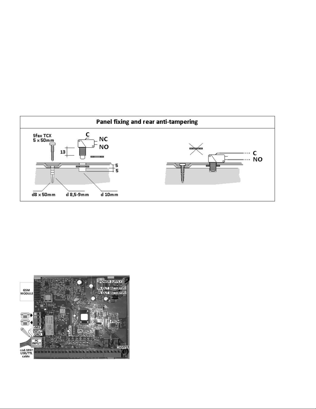
7.2 TAMPER PROTECTION AGAIN OPENING AND FORCED REMOVAL
The tamper spring switch located on the board assures that housing’s opening is reported. Make a 10 mm diameter/5 mm deep hole on the wall (see drawing) and place the supplied switch
between the hole in the wall and the housing’s opening (see page 4) to achieve tamper protection against its removal. The bulk of the switch must enter into the hole on the wall to prevent
tampering.
7.3 230V POWER CONNECTIONS - Carefully perform the following precautions:
Use flexible cable conductors with at least a 0.75 mm gauge.
Secure the cable by tightening the screws of the appropriate terminal board after having connected the two wires to the terminals. One of the terminals is protected by a 5x20mm
3.15A 250V fuse which must be removed during the connections and placed back again at the of the job.
Always disconnect the control panel from the power supply before working on the unit. The unit must be connected to the power supply using a 16A curve C Circuit Breaker.
Anchor the power supply cable to one of the fixtures using an appropriate non-removable nylon cable tie that avoids it being unplugged.
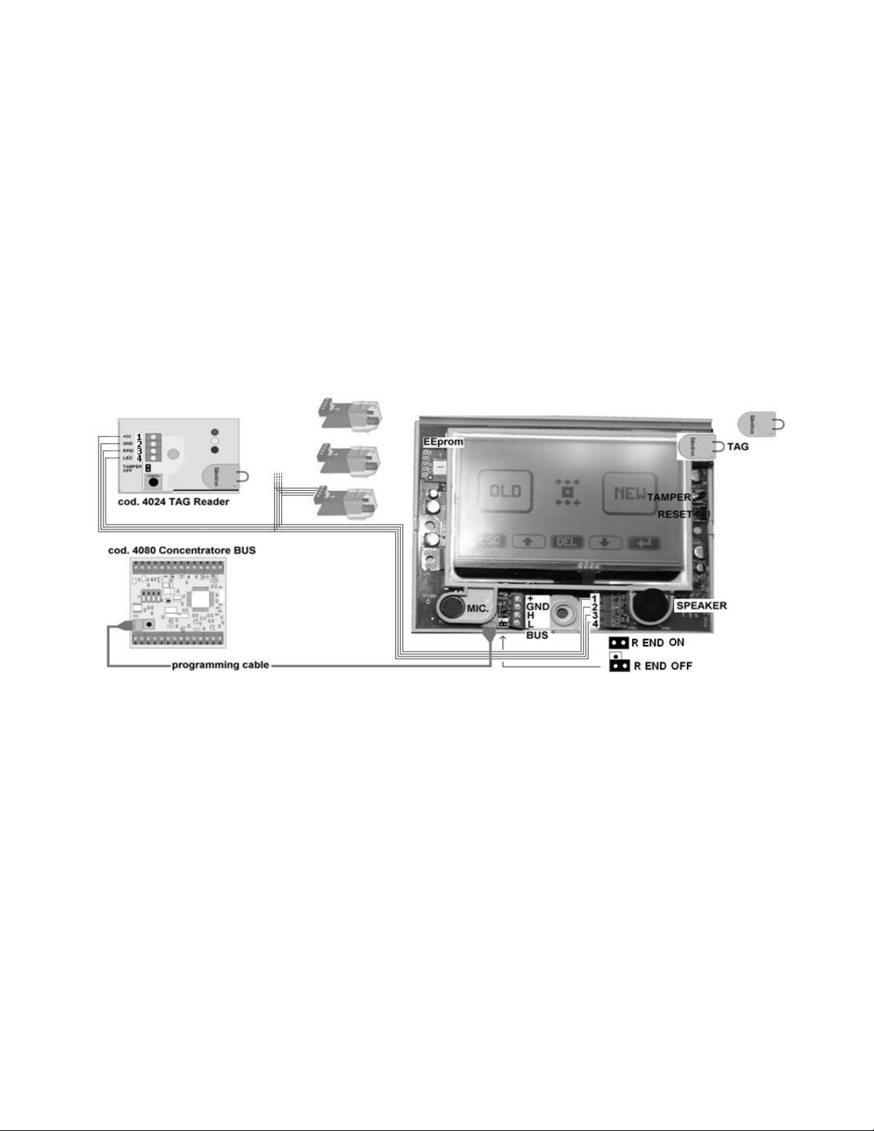
7.4 POWER SUPPLY UNIT –BATTERY AND SYSTEM'S BACK-UP POWER
The two power supply unit models are identified in the table on page 5
The following table displays the power supply units’ technical specifications with their maximum output current for the devices (OUTPUT CURRENT –do not exceed this value! ). The table
displays the system's back-up power capability in the event of mains failure (MAX BLACK OUT TIME) and the length of time required to recharge the batteries according to the EN 50131-
3:2009 Standard.
Batteries: you must use sealed lead-acid rechargeable batteries with a UL94-HB flammability rating.
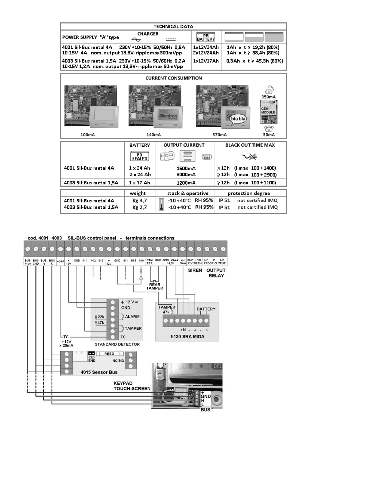
7.5 ELECTRONIC BOARD FITTED ON BOTH CONTROL PANELS
Sil Bus board 3790 connections:
14.4V power supply cable connector
one or two 13.8V battery cable connectors
Circuit board connections:
GSM module part no. 4099 with antenna. The antenna must be placed outside of the control panel
using the foreseen top opening.
1 PC to setup the control panel connected with cable part no. 5997
To the same connector can also connect the optional CCTV control board part no. 3798
an optional pre-amplified microphone to monitor audio in a different zone
the external PSTN telephone cables inputs
the telephone cables for the internal local network
all of the main terminal board cables required to install the system.
EEprom: a non-volatile removable Eeprom which can be used to preserve the data should the control panel
be replaced.
4-way DIP-SWITCH: 1 = see note 5.02; 2 = not used ; 3 = ON: terminal board's TAMPER input. Caution! For
regulatory compliance, use the input to connect tamper protection against forced removal; 4 –enable
(ON) the Bus end of line resistor where required.
12
7.6 MAIN TERMINAL BOARD CONNECTIONS
7.6.1 DETECTORS –BALANCED LINES
The conventional detectors directly connected to the control
panel or to the Bus modules operate over balanced lines thereby
requiring that the relevant resistors be installed as illustrated.
This allows to connect each conventional detector using only 3
wires. An appropriate wire gauge must be used in order to
prevent detector voltage drops.
You have a positive TC signal when the control panel is disarmed
which is used to lock standard detectors fitted with the relevant
input; In Test condition this signal is not ON, therefore detectors
will be working.
7.6.2 HARDWIRED BUS CONNECTIONS
The employed bus system –Can-Bus Controller Area Network - is
extremely reliable and does not require any special cables. It is
important to use the appropriate cable length and diameter to
prevent power drops at network ends which could lead to
devices' fault when their length exceeds 2000m. Use the
following table to size connecting cables. It displays which
voltage is available at the end of a Bus section with same
beginning at 12V based on the corresponding cable length and
device's electric energy absorption.
Example: 0.50mm gauge 100m long cable, 0.020A (20mA)
absorption of the connected device, 11,76. voltage to the device.
Voltage drop is acceptable in this instance.
Caution! Input 6 (auxiliary fault input): connect to GND with 47K
when it is not used.
Caution! Voltage drops that are less than 0.8V are acceptable for
the system's appropriate operations.
Caution! Should signal loss occur over long cable sections, install
a Repeater part no. 4009 at about mid line.

13
Diameter mm 1,000 - Resistance 0,027 - Cable length 100 m
Current (A)
0,015
0,020
0,025
0,030
0,040
Voltage (V)
11,9190
11,8920
11,8650
11,8380
11,7840
Diameter mm 0,050 - Resistance 0,060 - Cable length 100 m
Current (A)
0,015
0,020
0,025
0,030
0,040
Voltage (V)
11,8200
11,7600
11,7000
11,6400
11,5200
Diameter mm 0,022 - Resistance 0,120 - Cable length 100 m
Current (A)
0,015
0,020
0,025
0,030
0,040
Voltage (V)
11,6400
11,5200
11,4000
11,2800
11,0400
Diameter mm 1,000 - Resistance 0,027 - Cable length 200 m
Current (A)
0,015
0,020
0,025
0,030
0,040
Voltage (V)
11,8380
11,7840
11,7300
11,6760
11,5680
Diameter mm 0,050 - Resistance 0,060 - Cable length 200 m
Current (A)
0,015
0,020
0,025
0,030
0,040
Voltage (V)
11,6400
11,5200
11,4000
11,2800
11,0400
Diameter mm 0,022 - Resistance 0,120 - Cable length 200 m
Current (A)
0,015
0,020
0,025
0,030
0,040
Voltage (V)
11,2800
11,0400
10,8000
10,5600
10,0800
7.6.3 SAFETY OF THE SYSTEM
Although any Bus line tampering is reported by a specific alarm, any such tampering causes the failure of all of the devices connected to that line and therefore requires a remedial action. It
is therefore recommended that bus cables are not routed in pain sight, let alone outside of the protected zones.
7.6.4 END OF LINE RESISTORS: they are normally enabled (ON) on the devices' end of line as displayed in the figure. Warning! You may install up to 5 resis tors. In order to check devices'
connection and location, the control panel checks the line and reports if any setup modules are not connected along with their location.
7.6.5 REPEATER BUS part no. 4009: this device is used to electrically separate the bus line (for example, to protect Bus lines located outside of protected zones) and to amplify bus signal
when using very long cable lengths. Since it is not recognized as a Bus “module”, the repeater's operation is not checked by the control panel. It must be appropriated installed in such a
matter that it is protected against opening and/or removal, in order to comply with the standard.
8 KEYPAD OVERVIEW
You must connect the touch-screen keypad to the control unit and power the control unit (with battery or power supply) in order to program the system using the keypad. Sil-Bus are the
only hardwired control panels on the market that can be fully programmed at the factory, thereby requiring very few operations at customer's premises.
System's factory setup can be performed in one of the two following ways:
14
8.1.1 TOTAL PROGRAMMING: knowing where all peripheral devices are positioned, we can fully program them in the lab, appropriately number each device and then installed them when
they are already programmed.
8.1.2 PARTIAL PROGRAMMING: we only address the devices in the lab and then program them using the touch-screen keypad or a PC after the installation.
8.2 TOUCH-SCREEN KEYPAD - INSTALLATION
Opening the housing: open the keypad by applying pressure with a paperclip as shown in the drawing and then by removing the cover from the housing base.
Connections: connect the keypad to the control panel over the Bus line using a 4 cables as shown in the figure. You can connect up to 4 fl ush mount 4023 TAG readers. Any fault due to
tampering will not effect the Bus line since TAG readers are connected directly to the keypad.
Addressing connector (programming cable): the keypad is supplied with a cable to temporarily connect the Bus devices to be addressed. The device will continue to be addressed until same
is erased.
Calibration operations: the keypad can be adjusted as follows should screen not properly display images. Press the RESET key when the control panel is disarmed to display 4 crosses one at
the time. Adjust the keypad using a paperclip to touch the center of the cross.
Touch-screen operations : touch the icons that are shown on the display with your fingertips, as if they were keys. You must touch and hold your finger over the icon for 1-2 seconds in some
instances.
Built-in TAG reader : the keypad is fitted with a built-in TAG reader (digital electromagnetic key). The TAG must touch the closed keypad as shown in the figure in order to operate .
Caution! Connect keypad and TAG readers using a 4 way wire that is not longer than 20m.
Caution! The Touch-screen is provided of a 2k2 resistor connected between terminals 1 and 3 of the external TAG readers connectors. Remove the resistor when one or more than one TAG
reader is connected.
Note: TAG-BUS readers part no. 4022 are also available (see relevant instructions) which connect directly to the Bus line to arm/disarm the system as well as to control accesses and electric
loads remotely.
8.3 BUILT-IN TELEPHONE TRANSMITTER - FEATURES
Control panels are fitted with a built-in PSTN (landline) telephone transmitter which complies with ETSI ES 203-21 and R & TTE Standards, employing the ATS 2 transmission system with
emission that comply with EN 61000-6-3 standards. Voice transmission takes 12 seconds to start and contact-id digital transmission takes 19 seconds. See item 3.9 regarding operating
details.
Control panel can also manage an optional GSM telephone transmitter part no. 4099, which complies with ETSI ES 203-21 and R & TTE Standards, employing the ATS 2 transmission system
with emission that comply with EN 61000-6-3 standards. Voice transmission takes 12 seconds to start and contact-id digital transmission takes 10 seconds. See item 3.9 regarding operating
details. See paragraphs 11 and 12 to program numbers and messages and for additional details regarding their features.
8.3.1 PSTN CONNECTION: the external telephone line must be connected directly into the control panel, without placing any other equipment in between. Connect the line to the relevant
terminals taking into account their polarity. The devices located downstream from the control panel can be connected to the output terminals.
8.4 SETUP
The audio wizard will guide you trough all of the operations. The settings will not be lost even if the device is disconnected from the power supply.
Connecting the touch-screen keypad to the control panel
Temporarily connect the programming cable to the keypad to address modules.
Install optional GSM module part. no. 4099 (when foreseen) having placed the SIM card in its slot. Caution! You must either delete SIM card's PIN code or program it as 1234.
Connect the control panel to a battery or to the main power supply (ensuring that there are no electric risks).
Follow the instruction supplied in the table. Always confirm each performed step (). The name of the installation company along with at least one temporary user code must be
entered (see 3.4.1) since the user must authorized installer to access the control panel (see 3.4). The keypad will therefore display the Home screen again where you will be prompted to
enter the user code to authorize installer access. Please follow the instructions if you wish to install Silentron firmware (not compliant).
Caution! You will automatically exit from the main menus (not supplied with an ESC icon) when not operation is performed for over 5 seconds.

15
8.4.1 ADDRESSING BUS MODULES: connect a bus module to the addressing cable. Enter the TOOLS menu (wrench icon). The type of module that has been connected and the assigned
sequence number will display. You can quickly address the devices by connecting one module after the other (8.1.2), or you can begin to program the first connected module (8.1.1).
8.4.2 SETTING BUS ELEMENTS: if you choose to postpone setup, same will take place after the system has been installed using the Bus line and without directly connecting each device to the
keyboard. You can setup the system using the PC once all modules have been connected and installed (see par. 9.3).
8.4.3 OTHER SETUP OPTIONS: press the additional icons on the main menu screen to access other setup options. Please see the following table for their description.
8.4.4 SETUP SUMMARY TABLE
16
9. DEVICE SETUP TOOLS menu
Hardwired (detectors and similar devices) and virtual peripherals (codes) can be programmed in several stages, according to the installer's convenience. Each setup is stored in the system
and specific operations must be performed to delete it.
Caution! The menus display the option "OLD/NEW". Select OLD when you want to change an item that has already been addressed (see par. 8.1. and following). Select NEW for entirely new
operations.
9.1 SETTING USER CODES –5 DIGITS –See also 3.1 –3.5.2
Caution! A MASTER code user is enabled to perform this operation at any time.
Press the "keypad" icon to enter the menu. Select NEW to display the first available user code.
Follow the voice prompts and perform the explained procedures. You must first enter a mnemonic code for the user, after which you must enter:
which zones (A, B, C, D, E, F) this code is authorized to arm, followed by those that it can disarm. This selection allows you to enable users to control the entire system or only a part of it,
as required.
the name of the user of this code, in order to identify the author’s actions from the events recorded in the event history log.
Enter the code's type: MASTER or SLAVE (see 3.2) based on the authorization level that you wish to grant individual user.
Confirm the settings () to display the option to enter another code.
9.1.1 Editing - Deleting codes. Select OLD to enter and locate the required code (↑↓). Use the CANC (delete) option to delete the code or select the item you want to edit (), then confirm
the selection ().
17
9.2 TAG MANAGEMENT –ACCESS KEYS WITHOUT ELECTRIC CONTACTS
NEW: setting a new TAG. OLD: editing/deleting a TAG that has already been setup.
Press the "keypad with TAG" icon to enter the menu. Select NEW to display the first available TAG code. Place the TAG near the touch-screen as shown in the figure (figure par. 8.2). The data
entry screen will display showing the TAG code and location. If the TAG does not display and you instead hear three beeps, it means that the specific TAG has already been programmed. If
the TAG is not displayed and nothing happens, carefully start over from the beginning. If this fails, the TAG is probably faulty. Try with another-
When the data entry screen displays, enter data as prompted (user code, etc.) to complete the operation.
Enabling duress function (see 3.6.2). Highlight the option (↑↓) and enable it () selecting between "ON-code-OFF". After disarming the control panel with the TAG the user must also enter
the user code within 30 seconds when this option is enabled. The control panel will continue to be disarmed if user code is not entered, but phone calls transmitting the message "ROBBERY"
will be dialed.
9.3 SETTING BUS MODULES
Any device that is connected to the BUS line is defined as a MODULE. Many different types of modules are available, each one with its different function (please also see each module's
instructions). Each MODULE BUS must be addressed (8.4.1) and then programmed (8.4.2). This can be performed also at different times. Addressing takes place automatically while setup
requires knowing the module’s use and location within the alarm system.
The following instructions take into account that modules have already been address and that you must therefore select the OLD option to program them.
a) single purpose BUS modules: these are modules that have a single Bus "address"
1. 4010 BUS TRANSPONDER: module to be installed in standard detectors.
2. 4014 PIR BUS AA: intrusion detector (passive infrared)
3. 4013 DT BUS AA: dual technology intrusion detector (p.i.r. + radar Doppler)
4. 4021 SLAVE BUS TOUCH SCREEN: additional optional keypad
5. 4035 RELAY BOARD: actuator controlling electric loads
6. 4015 BUS SENSOR: magnetic contact (Caution: terminal board inputs are not compliant and therefore not usable).
7. 4022 BUS TAG READER: TAG key reader
b) multi-purpose Bus modules: these are modules that feature several addresses and that control several devices. Their addresses are displayed on the touch-screen when they are
programmed for the first time. You must select (↓↑), confirm () and enable (↓) one address at a time. Confirm settings using .
1. 4080 BUS Concentrator 4 + 2: 4 balanced inputs are available (the two NC inputs are not compliant)
2. 4081 BUS Concentrator 6: 6 inputs are available.
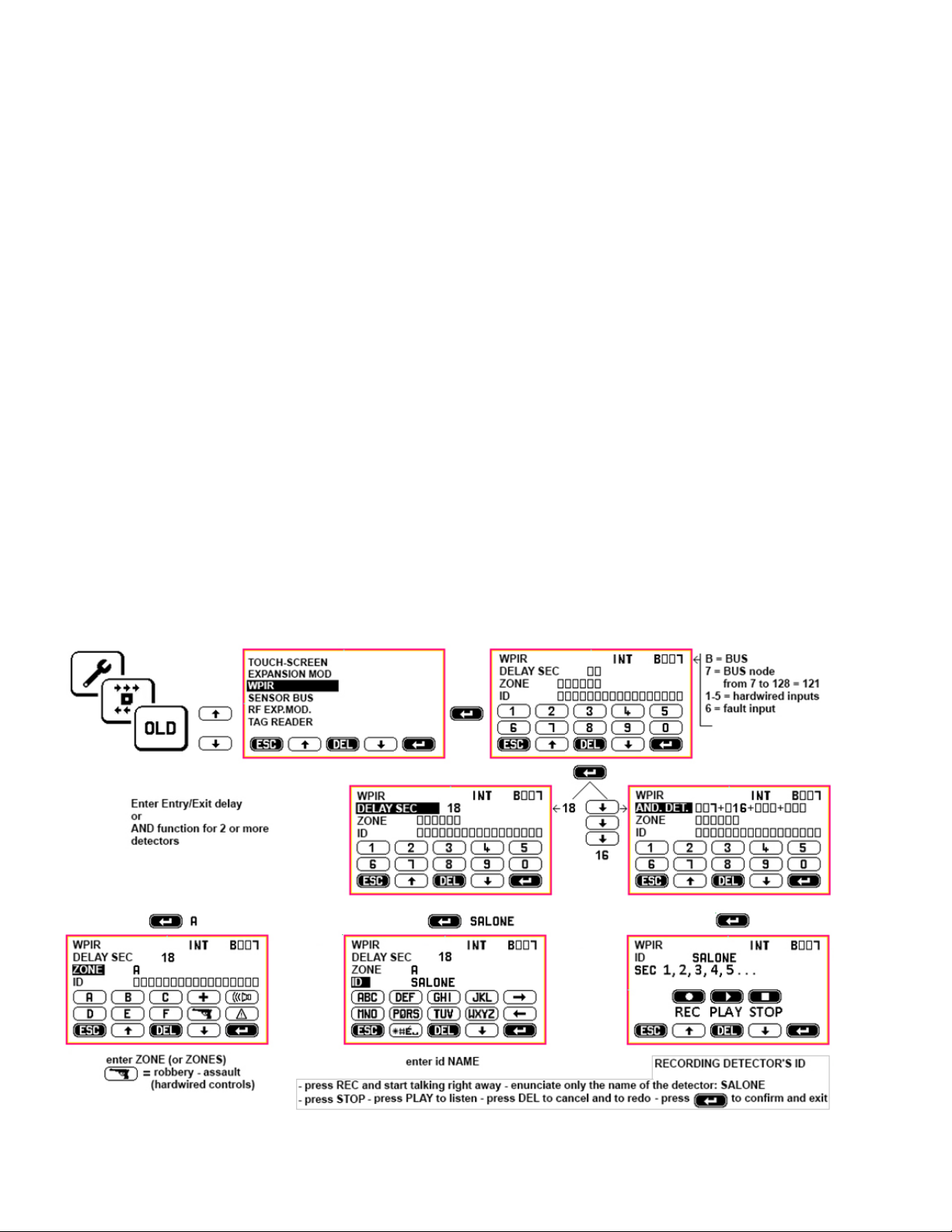
9.3.1 SETTING SINGLE PURPOSE BUS DETECTORS (a1, a2, a3, a6)
Select the OLD option, then the addressed detector and setup the following operating parameters.
ENTRY/EXIT DELAY: enter seconds from 0 to 45 (Warning! Setting entry/exit delay automatically disables DET.AND. function. –see paragraph 9.3.1.1)
ZONE: enter the unit’s operating intrusion zone/zones (one unit may be used for two or more zones) or use the icons to select the 24 hour zone (only one for each detector –functions
are not compliant).
ZONE OR/AND: if the detector has been associated with several zones the "OR" text will display. Select between zone AND (↓) and zone OR.
OR = the detector is enabled when a single zone is ON. AND = the detector is enabled when all zones are ON).
ID: identification (the location of the device, e.g. "PIR detector kitchen").
REC: perform voice recording identifying the device for audio playback. The recording is played back after the alarm audio messages and allows to precisely identify which device has
triggered the alarm.
Caution! See 9.1 for information regarding recording times.
Caution! Do not confuse zone OR and AND with detector’s AND function (see below).
Caution! When CCTV board part. no. 3798 is installed, its parameters will also display. Please see the board's instruction manual.

18
9.3.1.1 DET.AND. FUNCTION (intrusion detector's AND function and/or 24 hour function)
The DET.AND. function can be enabled by pressing ↓ instead of setting entry/exit delay time. This function allows to minimize the likelihood of improper alarm being triggered, especially if
detectors operate in tough conditions. With this setup, the signal triggered by one or more detectors will be handled as follows:
a) RECIPROCAL "AND" (two or more detectors are setup with the AND function and linked together)
- An alerted AND detector activates a not adjustable alarm delay of 30 seconds.
- The alarm is triggered only when another AND function detectors is alerted within the preset 30 seconds.
Application: this function is used when two are more volumetric detectors (or a volumetric detector + a barrier or other device combinations) protect the same zone where an intrusion
would be reported by all of these devices.
b) NOT RECIPROCAL "AND" (two or more detectors are setup with the AND function and are linked with other detectors but not vice versa)
Example: detector 10 with AND function linked with detector 11 and 12 - detector 11 with AND function linked with detector 10 - detector 12 is set with the AND function.
- Alert signal from 10 + from 11 (or 12) received within 30 seconds = alarm
- Alert signal from 11 + from 10 received within 30 seconds = alarm
- Alert signal from 10 + from 12) received within 30 seconds = alarm
- Alert signal from 12 + from 10 (or 11) = no alarm
Application: outdoor protection of zones that are not foreseen by the EN 50131 standard.
c) AND ALL (all detectors located in the same zone are setup with the AND function and linked one another): the alarm is triggered only when at least two detectors are alarmed within 30
seconds.
Application: indoor protection of zones where an intruder is likely to trigger at least two detectors within 30 seconds. This is the best solution to use when many volumetric detectors with
signals crossing each other are installed in large zones with interferences.
d) SETTING "AND" FUNCTION
The following must apply in order to be able to setup a detector with the AND function:
detectors must already be setup and you must have written down the number of their location
detectors must be setup in the same zone/zones or not be set for any zone.
The first detector programmed with the AND function is setup as the MASTER (M) detector. When you enter the number of the other AND detetectors' location along with the one of the
first and confirm the settings with , these become SLAVE detectors that are automatically assigned to the MASTER detector of that zone/zones. Continue setup procedure until you enter
detectors' ID and your perform the voice recording for the MASTER detector.
e) RECIPROCAL "AND": the slave detectors that have been setup as above are automatically programmed with a mutual "AND" function.
You must therefore retreive each one of them one by one (↑↓) after selecting the OLD option to complete their setup and enter their ID () and voice recording.
f) NOT RECIPROCAL "AND": the system automatically sets up detectors for reciprocal AND function. Press DEL when the detector's location number is displayed if you do not wish to setup
the detector with the reciprocal AND function. Press to confirm selection. Continue setting up the device by entering its ID and voice recording.
g) AND ALL : press (↓) at the AND row to skip the boxes with the location numbers until the text ALL is displayed. Press to confirm the selection. Continue setting up the device and enter
its ID and voice recording.
You must setup at least another detector with the previous detectors options when AND ALL is selected. The AND ALL option is used to speed up programming when you have more than 4
detectors located in the same zone that need to be setup. The AND ALL option allows you to have several groups of detectors s etup with the AND function among each other, but only one
group for each zone.
h) DISABLING THE "AND" FUNCTION: Call up the MASTER detector and select EX. DELAY. (entry/exit delay - with zero or adjustable time) option to disable the AND function. Since setting
entry/exit delay option excludes the AND function, all detector will resume standard operations.
i) "AND" EVENTS LOG: Alarms triggered by AND detectors are all stored in the event history log. The detector that triggers the actual alarm is displayed with an “AND” label.
l) EXCLUDING "AND" DETECTORS: Caution! The protection of the involved zone is lost when an "AND" detector is excluded. Protection is partially lost if an "ALL" detector is excluded but
there are at least two other detectors programmed in the same way.
m) DELETING "AND" DETECTORS: a detector can be deleted through the standard deleting procedure only after the "AND" function has been disabled.
9.3.1 SETTING SINGLE PURPOSE BUS MODULES (b1, b2)
The 4 and 6 zone concentrators are fitted with 4 or 6 balanced line inputs which allow to connect 4 or 6 conventional detectors. Each one of these detectors takes up one of the 121 available
Bus nodes. After having performed the addressing procedure (9.3. b), select (↑ ↓) each input where a detector has been connected. Use the same procedure used to setup a single purpose
module (9.3.1) to program the detector with all of the above described functions. Caution! You can not program these detectors using the local keypad or remotely since they are not
directly connected to the Bus: they must be setup on site.
9.3.3 SLAVE TOUCH SCREEN SETUP –a4
The system allows you to use 6 optional touch-screen keypads in addition to the first one (MASTER). The keypads can be used only for zones' ON-OFF controls since programming and
changes can be made only with the MASTER keypad supplied with the control panel. Keypads must first be addressed after which they may be programmed to operate with their total
capability or with a limited one exactly like a TAG key. Follow the displayed instructions and make the required selections (ZONES, TAG) to setup the keypads. You can setup each SLAVE
keypad to control only one zone and to have its own TAGs which may not be read by other keypads. This allows to configure multi-user systems where each keypad manages only its own
zone (or zones).
The audio and text messages of a SLAVE keypad with limited operating zones are broadcasted only for the enabled zones. Any MEDICAL ASSISTANCE, ROBBERY and SIRENS ENABLING keys,
will likewise enable telephone calls. Only the numbers assigned to the enabled ZONES will be dialed.

19
Caution! A conflict due to incorrect programming could occur. If, for example, a user code with limited access is enabled only for zone A and zone B and a keypad only handles zone C and
zone D, this code is clearly unable to use that specific keypad.
9.3.4 SETTING BUS RELAY BOARDS TO CONTROL HOME AUTOMATION FUNCTIONS - a5
These boards can be programmed to actuate control panel’s automatic commands or manual commands over the keypads and remotely only by SMS.
List of available commands (S = seconds of time)
Monostable (S): press HOME AUTOMATION CONTROLS on the keypad and/or send the appropriate SMS to switch the for the preset time (1-999 s)
BISTABLE: press HOME AUTOMATION CONTROLS on the keypad and/or send the appropriate SMS to permanently switch the relay until the opposite command is received
GENERAL ALARM (S): the relay switches for the preset time (1-999 s) in the event of a general alarm.
EXTERNAL ALARM (S): not foreseen by the Standard - not usable
CONTROL PANEL ON/OFF: the relay switches to change the assigned zone/zones’ condition
WEEKLY TIMER: the relay switches according to preset weekly schedule (see 10.1.3)
ALARM DELAY: the relay switches for the preset delay time when a delayed detector is alarmed.
TAMPERING (S): the relay switches for the preset time (1-999 s) when tampering is detected.
SIREN ACTIVATION (S): the relay switches for the preset time (1-999 s) when the appropriate keypad key is pressed
MEDICAL ASSISTANCE (S): the relay switches for the preset time (1-999 s) when the appropriate keypad key is pressed.
ROBBERY MESSAGE (S): the relay switches for the preset time (1-999 s) due to a robbery alarm
TECHNICAL ALARM (S): the relay switches for the preset time (1-999 s) due to a technical alarm
FAULT (S): the relay switches the relay switches for the preset time (1-999 s) due to a fault
BUS ALARM (S): the relay must be associated with a single detector and switches for the preset time (1-999 s) only when the control panel is armed (additional reporting of alarms for
a specific detector)
TAG READER: the relay switches when it recognizes one or more TAGs - select mono or bistable mode
HOME AUTOMATION: the relay must be associated with any one detector and switches for the preset time (1-999 s) when the control panel is armed as well as when it is disarmed
("chime" function)
Programming is intuitive: simply follow the audio instructions and confirm the selections.
9.3.5 SETTING BUS TAG READERS –a7
To allow the user operations from different zones, the control panel allows to install up to 16 Bus TAG readers in a system. Each reader takes up one of the available 121 bus nodes and must
be addressed and then programmed to be identified in event history log. Installation operations are described in the technical documentation supplied with the device.
9.3.5.1 BUS TAG READER ADDITIONAL FUNCTIONS (not IMQ compliant):readers can be used to control electric locks when they used with a relay board part no. 4035 thereby becoming the
basic elements of an access control system where accesses are stored in the event history log. Caution! You need to download the event history log often (up to 500 events) to prevent data
loss when there is a high number of daily operations. Download can be performed using a PC.
9.3.6 ADJUSTING BUS DETECTORS
The keypad can directly manage only the Bus detectors that have been already programmed. Select the required detector from the list (↑↓) to access adjusting mode. If no adjustments are
made, Bus detectors feature the following average default values:
SENSIBILITY: 75% PULSE COUNTER: 02 INTEGRATION: 50%
Since each detector is automatically recognized by the system as you access adjusting mode, the appropriate adjustment screen only shows the adjustable features of the specific detector.
Look for the parameters that you wish to adjust (↓↑), confirm the selection ( ) and make the required adjustments (→ ←).
9.3.7 MANAGING HARDWIRED INPUTS –SETTING CONVENTIONAL DETECTORS (TERMINAL BOARD)
This item is used to program the hardwired detectors that are directly connected to the 5 balanced alarm inputs and the sixth fault input. See terminal board diagram and perform the
necessary detector adjustments. Press icon to display the first of the 5 inputs that is available (input 6 = FAULT).
press to enter setup mode and to program the first detector that has been connected to input 1 .
press ↑↓ to move from one input to the other.
Enter all of the required data as previously done for Bus detectors (see 9.3.1).
9.3.8 EDITING/DELETING BUS MODULES : Modules may be adjusted (select OLD to display it and to make changes), deleted (select DEL) or replaced (when faulty).
9.3.8.1 REPLACING A MODULE: to replace a module simply write down the number of its location and access setup mode. Disconnect it from the Bus line and then press DEL to display the
prompt REPLACE-DELETE . Select REPLACE and press enter. Connect the new module to the keypad using the programming cable and press . The new module will replace the previous one
maintaining the same inputs setup.
Caution! If you press DELETE the module and everything that was connected to it will be deleted.
10 SYSTEM SETTINGS menu : This menu is used to set the system's adjustable settings. The user can access some of these settings.
Time functions: these are all of the functions related with the "time" parameter that can be set according to requirements.
Managing SIM card of GSM module part no. 4099 (if installed): these are the controls that one can use to avoid SIM cards communication failure.
Managing control panel’s relay: this are the settings of the control panel’s built-in relay which features various useful functions.
Isolating (excluding) detectors: this option allows to exclude/replace a detector.
Caution! An excluded detector does not trigger an alarm but its reports are displayed in the event history log.
GSM/PSTN Priority (where GSM module is installed): this option allows to select which communication device has priority.
Several utilities: this option offers functional aspects to take into account and to defined with the user.
20
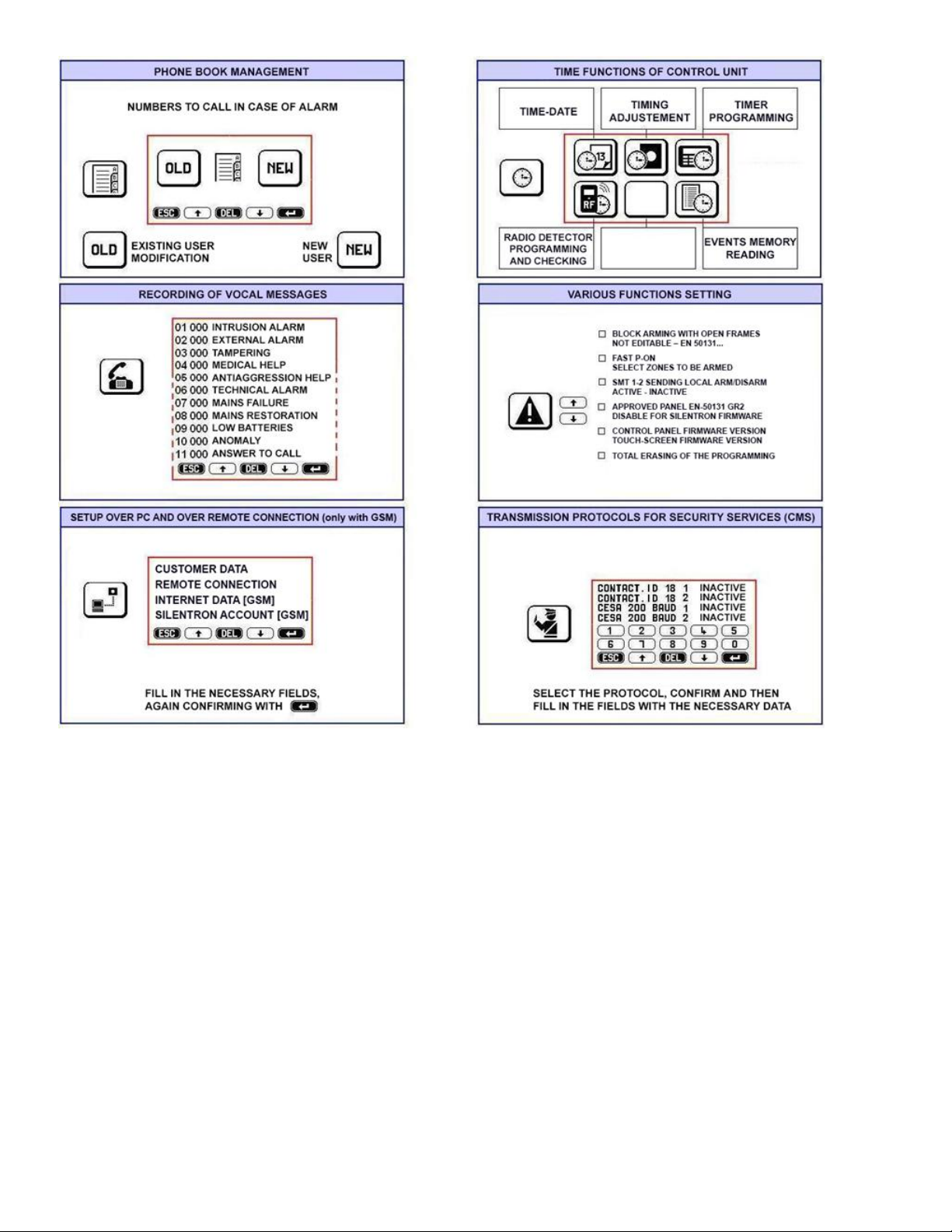
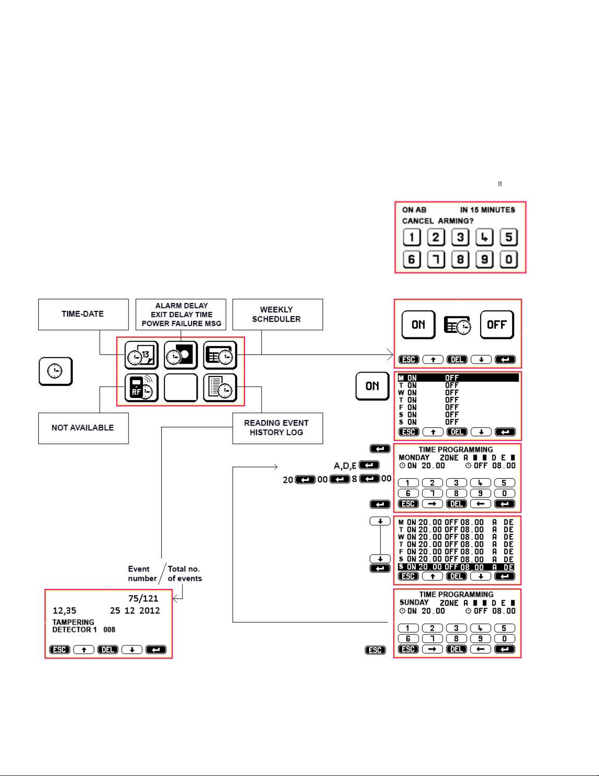
10.1 TIME FUNCTIONS (see figure)
Since most settings are extremely intuitive and easy to perform by following the audio wizard and the screen prompts displayed on the keypad, these easy settings are not described in this
manual.
TIME-DATE: this setting is reset when the system is disconnected from the power supply. For this reason it should be accurately set at the end of the installation since the control
panel's date and time are recorded in the event history log.
TIME ADJUSTMENTS –default settings are supplied between brackets:
a) ALARM TIME - from 1 to 999 seconds (180), it applies to any type of alarm.
b) EXIT TIME - from 1 to 99 seconds (60), this is the time that elapses before control panels is actually armed.
230V POWER FAILURE MSG: from 1 to 99 minutes (60), this is the time that elapses before the event is transmitted over the phone.
SUPERVISION MSG: from 1 to 25 hours (25), this is a phone call or a text message that is sent at programmed time intervals to confirm telephone’s proper operation.
WEEKLY SCHEDULER: it allows to set when the control panel’s is automatically armed and disarmed for seven consecutive days - from Monday to Sunday. It does not take into account
any weekday holiday.
Caution! The control panels is automatically armed (forced arming) if a detector is alarmed regardless of scheduler settings.
Caution! If an alarm takes place when the control panel is set to automatically disarm, disarming will occur at the end of preset alarm time.
10.1.1 SETTING WEEKLY SCHEDULER
All fields are empty when the scheduler is programmed for the first time. Enter the time settings and the zone settings for the first day and confirm each entry using . When the first day
has been completed, these settings will be copied over to all of the seven days. Scroll (↓↑) to select any days where you wish to set different schedules and press to edit. Confirm each
entry.
Caution! a) You must set the ZONES that are to be armed/disarmed.
b) You must set at least a one minute difference between the settings, e.g. ON 09,00pm - OFF 09,01pm
(the system will not accept 09,00pm).
c) Since time always goes forward, if you set arming (ON) at 23.00 hours on Monday and disarming (OFF) at 20.00
hours on Monday, the system will continue to be armed for the entire week.
10.1.2 OPERATION: an alert sounds (3 beeps) every minute 15 minutes before the time in which automatic arming has been set.
During this period automatic arming can be canceled by entering a valid code on the keypad.
Caution! In this case you will need to manually arm the control panel if and when required. From there on the scheduler will continue
to operate automatically.
This manual suits for next models
1
Table of contents
Other SILENTRON Control Panel manuals


Popular Control Panel manuals by other brands

Sony
Sony RCP-730 Maintenance manual

S&S Northern
S&S Northern Merlin CT1650+ user guide

Hanna Instruments
Hanna Instruments BL 983321-0 instruction manual

Balboa
Balboa TP800 series User interface reference

Irrifrance
Irrifrance Irridoseur 4 Programming manual

Trox Technik
Trox Technik EASYLAB Assembly and operating instructions


