SILENTRON 5500 Silenya HT GSM Top User manual

1
Instruction manual
CONTENTS OF THE FIRST SECTION – USER AND THE INSTALLER MANUAL
1) FOREWORD
Availables Firmwares of the control panel 2
2) FEATURES
Overview and differences between the two control panel models.
2
Diagram of EN compliant system (fully expanded configuration) - Hardwired external devices.
3
Table of EN 50131 products and accessories
3
System project - Audio Wizard - Least expanded configuration
4
3) USER MANUAL
User/Installer codes and access levels - Meaning of keys
4
User Access for setup functions. User is authorized to setup messages, tools, settings, remote
technical support, installer code, temporary exclusion (isolation) of a detector.
4
User Access for operation purposes. User is authorized to display the event history log, perform
testing and setup relay 1.
5
Event Alert - User operations (figure): arming/disarming from control panel.
6
Arming/disarming using remote controls and keyboards - Automatic arming.
7
Disarming under duress - Automatic relay 1 operation.
7
Alarm functions - Control panel’s telephone section - voice messages and SMS – Call. 7
Telephone calls to central monitoring station – Medical assistance calls - Calls to the control
panel
8
Remote Control functions - Editing address book numbers with SMS – SIM card balance –
Remote audio monitoring
9
Hands free telephone conversation - Other functions - Setup from PC
9
User Information
9
4) INSTALLER MANUAL
Precautions - Opening, positioning and fastening – Tamper Protections - Network connection 10
Testing radio reception - Top Models (5500-5502): Technical Specifications
11
Electronic board of Top models: connections 11
Free Models (5501-5503): Technical Specifications - Back-up Power – Electronic board 12
Built-in Telephone Transmitters: Specifications 13
Commissioning - initial setup 14
Diagram of menu when control panel is first commissioned - Programming procedure - Messages 15
Editing voice messages - SMS -SMT - Event Messages 15
Setting Phone book - Tools: setting external devices (remote controls, alarm zone codes, AND
function, 24H areas.
16
Setting hardwired zone - Functions Setting Menu 16
Function Setting (continued) - Digital Protocols 17
Additional data on digital protocols 18
GPRS transmission (data) - remote technical support (remote maintenance) 19
5) PC MANAGEMENT
Operations to perform settings over the PC 19
6) SETTING ALARM DEVICES
Receivers, sirens, keypads 20
7) APP
Utilities for Smartphone users 21
8) APPENDIX
EC compliance to applied regulations 21
SILENTRON FW
MANUAL
Variations supplied by Silentron’s firmware 22

2
1 FOREWORD - Availables Firmwares
1.1 Declaration of conformity
The manufacturer declares at chapter 8 that the panels here described
are conforming to the UE regulations when them are used with the
firmware EN 50131.
1.2 SILENTRON firmware
In compliance with general regulation criteria, this firmware allows to
perform better solutions for end-users. These operations are therefore
not strictly compliant. Main not compliant operations are: 1) external
detectors’ differentiated alarm management, which the standard does
not mention 2) immediate alarm transmission dynamics, the standard
requires that it be delayed, 3) immediate display of alarm location during
partial arming. for a better information to end-user. The other operating
differences are specified in the paragraphs pertaining to each topic. IMQ
certification will be void when the other optional firmware is selected.
Installer and user are responsible for firmware selection. The
manufacturer is available to maintain that some of the operational
decisions envisaged by its firmware improve user’s safety and usability.
1.3 Silentron firmware selection
The control panels are developed with the EN 50131 firmware and you
must enter the appropriate menu (see 4.8.5.20) to change firmware
version. Please refer to the specific instruction manual should you wish
to replace the firmware. All of the programmed settings will be
maintained when firmware is replaced.
2 OVERVIEW
Silenya HT control panels are devices that allow to manage and control
alarm and home automation systems. All external devices and functions
are setup according to each location’s requirements.
Various accessory devices may be hardwired to the control panels and
control panels may be fitted with home automation actuator boards.
These devices are used to handle the control panel, detect various
kinds of events and generate various types of warning and/or deterring
alarms.
2.1 DIFFERENCES BETWEEN THE CONTROL PANEL MODELS
Silenya are extremely powerful control panels that may be used to
develop small and large systems using from 1 to over 90 detectors. You
can select between four available control panel models according to the
type and size of the system to be installed. The models feature different
power supply modes and some models are supplied with a built-in
GSM-GPRS module while some types do not. It is not possible to add
elements to a model that is not supplied with them since the different
features are native ones. All control panels are equipped with a built-in
PSTN telephone transmitter (landline line).
5500 Silenya HT GSM Top: primarily powered by 230V mains, with
built-in GSM/GPRS module
5501 Silenya HT Top: primarily powered by 230V mains, without GSM/
GPRS module
5502 Silenya HT GSM Free: primarily powered by alkaline batteries,
without 230V, with built-in GSM/GPRS module
5503 Silenya HT Free: primarily powered by alkaline batteries, without
230V, without GSM/GPRS module
2.1.1 IMPORTANT NOTE: This manual sets out the features of the
most complete model, 5500 Silenya HT GSM Top. Please note that all
of the functions that require a GSM/GPRS telephone module will not be
available for the models supplied without this device. Likewise all of the
functions linked with a mains power supply will not be available for the
"Free" battery powered models. This manual therefore applies to all
models and highlights only the shortcomings which do not directly result
from the different mentioned above features. Examples:
a) Models without GSM/GPRS module do not require a SIM card, do not
send SMS and therefore do not require SMS settings to be performed.
These models can receive outside calls only from a PSTN landline. b)
Battery-powered models which are not powered by the main power
supply do not feature hardwired inputs/outputs. The GSM/GPRS module
of these control panels cannot be constantly on and is activated only
through the control panel’s control and/or in the event of an alarm.

3
2.2 EXAMPLE OF A FULLY EXPANDED CERTIFIED SYSTEM
Caution! Up to 99 supervised external devices (detectors, keyboards, sirens, etc.) may be connected to the system. There is no limit as far
as the number of unsupervised (not certified) external devices is concerned.
2.3 CONVENTIONAL HARDWIRED EXTERNAL DEVICES (Top models only)
Control panels are fitted with hardwired lines to which you can connect:
•up to 6 detectors powered over a 3 wire balanced line
•no. 1 (or more) self-powered siren with built-in battery
•no. 1 (or more) not self-powered built-in siren
•no. 1 electromagnetic key (TAG) supplied with at least 300 million code combinations to arm/disarm control pane over a balanced line.
•no. 1 control board with metal box part 5598 (installation under the panel) for 1-4 hardwired CCTV cameras
•no. 1 WiFi control board part no. 3796 (installation into the panel) for operate 1-4 wireless PhotoPir (detector with camera onboard)
2.4 EN 50131 WIRELESS SILENTRON PRODUCTS
CODE DESCRIPTION Grade Class
5510 PIR HT AA* - Passive Infrared Detector - LB 32442 PCB 89423/C-1,C-2 1 II
5510LC PIR HT - Passive Infrared Detector - LB 32424 PCB 89424/A1-A2 1 II
5512 Silent LR DT HT - Passive Infrared Detector - LB 32440+32411 PCB 89421/A 1 III
5514 Silent DualTech HT - Dual Technology Detector. PIR + MW - LB 32430+32401 PCB 89420/B 1 III
5515 B/M Sensor HT ** - Magnetic Contact - LB 300301 PCB 89235/C 1 II
5517 B/M Window PIR - Passive Infrared Detector - LB 300091 PCB 89316/C 1 II
5518 DT HT AA * - Detector DualTech. PIR + MW - LB 32423+32412 PCB 89423/C1-C2 1 II
5521 B/M PIR HT - Passive Infrared Detector - LB 300095 PCB 89317/C 1 II
5522 B/M Small PIR HT - Passive Infrared Detector - LB 300099 PCB 89319 1 II
5524 PCK HT – 2 way remote control - up to 32 - LB 300495 PCB 89237/B 1 II
5528 KeyPad HT bi-directional keypad - up to 32 - LB 300431 PCB 89238/B 1 II
5532 SIRENYA HT bidirectional outdoor siren - LB 30446 PCB 89277/B 1 III
4
2.5 INSTALLER’S RESPONSIBILITY & PERFORMANCE
Each alarm system consists of several external devices (detectors, sirens, control points, keyboards, etc.) which are controlled by one of the
control panels that are featured in this manual. This manual describes all of the panels’ features, their use and their operation. A professional
installer has the essential task of identifying which functions are required by the customer, to foresee the safety measures required by the
system and to install the system with diligence and professionalism. The installer must integrate the instructions supplied in this manual with
the operating variables being implemented in the system in order to allow the user to fully master all of these functions
2.5.1 INSTALLER AND USER AUDIO WIZARD
In order to facilitate the system’s implementation and use, these control panels feature an audio wizard that illustrates the available
operations during their use. For this reason some marginal and/or highly intuitive aspects of the control panels may not be mentioned in this
manual. These control panels have been designed in such a way that no user operation could damage the system.
2.5.2 MINIMUM SYSTEM REQUIREMENTS FOR EN 50131-1 AND FOLLOWING STANDARD COMPLIANCE
The system must foresee at least one battery or battery pack powered control panel, an enabled built-in telephone dialer, a detector and an
external siren (grade 1 certified). Up to 99 devices (detectors, sirens and keypads) may be managed with a fully expanded system. The
detectors are be divided into three groups (zones) and each zone can be individually armed.
Up to 6 hardwired detectors may be connected to Top model control panels using a balanced line. You can freely select for which of the
three zones you wish to setup the detectors.
3 USER MANUAL
The following figures describe all of the operations that the user can perform using the control panel keypad and/or the remote control. The
figures specifically describe how to partially and fully arm the system, how to test it and the user settings.
Caution! Each item that is entered using the keypad must be confirmed using the () key.
3.1 ACCESS CODES - Caution! Keypad locks for 3 minutes when the wrong code is entered more than 5 times!
You must use two 4 and 8 digits access codes, the USER code and INSTALLER code, in order to operate the control panel. These different
codes are setup by the installer during the installation. After the installation, the user must change the temporary user code programmed by
the installer to have full system’s ownership. The installer will therefore need the user’s authorization (the new code) in order to perform any
changes to the system after this time.
Enter the USER code– Confirm it () – scroll down to INSTALLER CODE – enter INSTALLER code.
3.2 ACCESS LEVELS
Level 1: Control panel can be accessed by anyone: anyone can see the display’s basic screen
Level 2: User access: user accesses control panel by entering a 4digit code
Level 3: Maintenance access: control panel's settings can be accessed only by entering the installer code
Level 4: Manufacturer access: control panel’s upgrading operations may be performed only when the control panel is disabled.
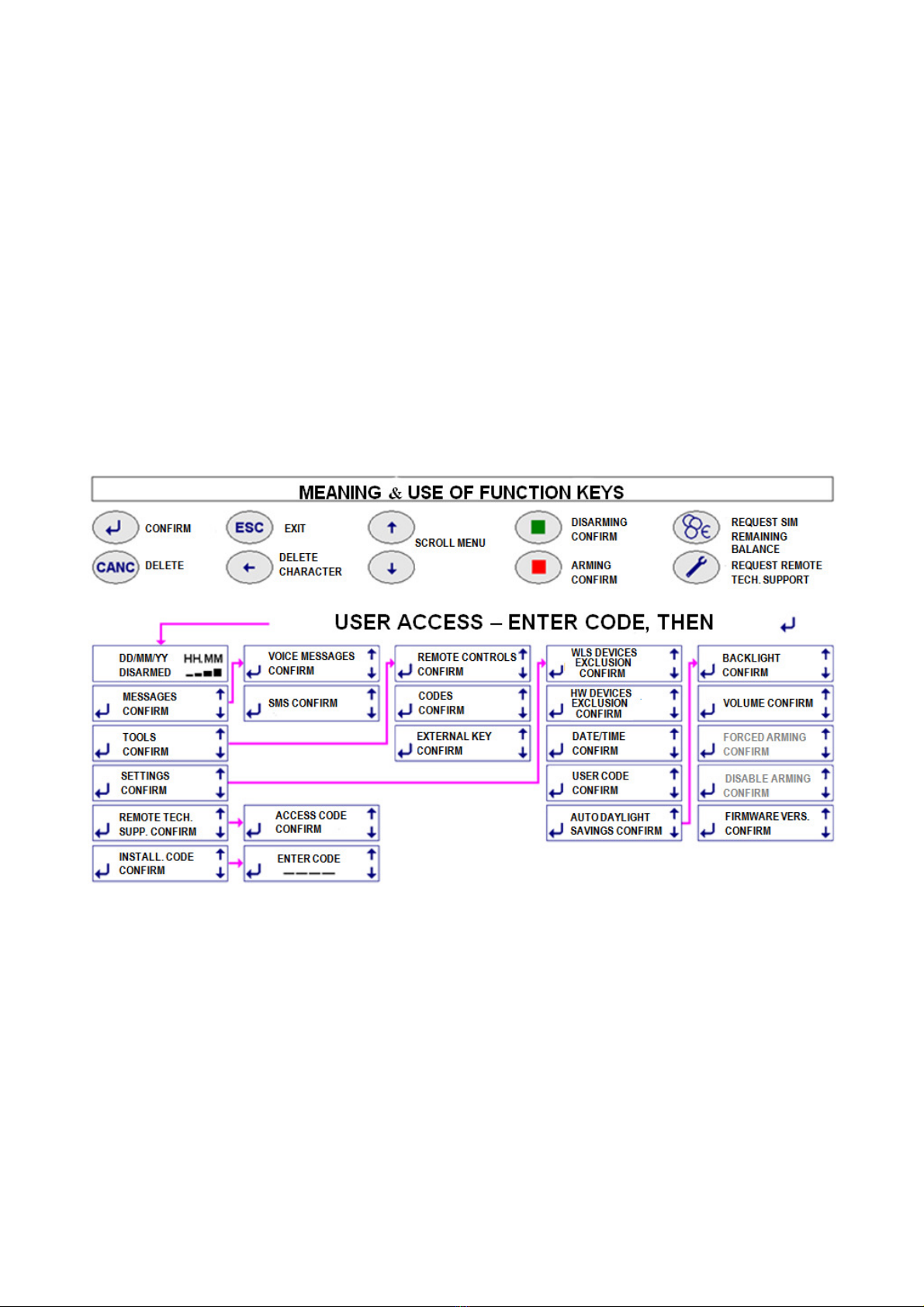
3.3 MEANING OF FUNCTION KEYS - see drawing.
3.4 USER ACCESS FOR SETUP PURPOSES ( see previous table)
Once the user code is entered, followed by , the available menus to setup and operate the control panel are displayed. Operations are
intuitive and described in the following sections.

5
3.4.1 MESSAGES: used to record/delete the voice messages and SMS (see 4.8.2 ) that are sent over the telephone to the numbers setup
in the phone book during the relevant event.
3.4.2 TOOLS : used to setup new remote controls, to delete any ones that may have been lost and to edit previously setup remote controls
(see 4.8.4.1). It is also used to create, delete and edit arming and disarming codes with different restrictions (see 4.8.4.2) as well as to setup
an additional TAG with the same options same has been installed.
3.4.3 SETTINGS: used to access sub-menus for the following options (see 4.8.5) :
•Isolate (exclude) one or more hardwired or wireless detectors. The events signaled by the excluded detectors will be stored in the
system without triggering any other function.
•Update date and time
•Change USER code, to be performed after installation to detain be exclusive access.
•Enable or not enable automatic daylight saving time.
•Enable display’s backlight permanently.
•Forced arming: only the installer can access the function that allows to program system arming at specific set times.
•Disable arming: this function is not available.
•Display your system’s firmware version. It may be updated or implemented as required.
3.4.4 REMOTE TECHNICAL SUPPORT: to create a code that is required to request remote assistance. This code can be used to connect
the control panel to the installer’s servicing center by dialing it over the telephone when the control panel answers the call. This operation
automatically disables the control panel as the service is enabled. The control panel will be automatically enabled when the connection to the
servicing center ends. Caution! This code must be different from the user code: see 4.10.
3.4.5 INSTALLER CODE: by accessing this menu, user will grant installer's access as this is where the installer will enter his own access
code. This procedure will ensure that the installer is not able to access the unit without user’s authorization.
3.5 USER ACCESS TO USE THE SYSTEM (see following table)
As illustrated, control panel’s operations can be accesses with different modes.
3.5.1 TESTING CONTROL PANEL - USER/INSTALLER ACCESS - SYSTEM ADJUSTMENTS
3 types of tests are available: CONTROL PANEL ( DETECTORS) – DIALER - GPRS (digital messages sent to the central monitoring
station) . When TEST mode is enabled using USER code, no alarm will be triggered, but tamper protection will continue to be enabled.
Caution! You must enable TEST mode using the INSTALLER code in order to change any batteries and/or service the system since this
code will also disable tamper alarm. This also allows you to access radio signal test mode (see FIELD METER 4.2).
Procedure: test the remote controls and trigger all detector’s alarm by opening protected doors/windows, moving inside areas that are
protected by volumetric detectors, breaking infrared barriers, etc. Always wait at least 5 seconds between alarms, up to 99 subsequent
alarms will be stored in the system. Perform the test in two phases in the event of multiple detectors. Once testing has been completed,
check that each alarm has properly transmitted as well as its reception range over the two operating CH1 and CH2:
H = excellent, M = good , L = low. All range levels are to be viewed as effective for signal reception purposes since the test is carried out
with the receivers’ attenuation required by the standard. Perform a “real” test by arming the control panel and triggering an alarm should
there be no display for either frequencies as the signal is attenuated during TEST mode in compliance with Standard 50131 and the unit
could be properly operating. Contact support service in the event that no alarm is triggered.
TESTING WIRELESS SIRENS: in TEST status, sirens have been properly connected if a beep is heard when pressing the red button.
3.5.2 TESTING DIALLER and GPRS : enter the required number to be dialed and verify the outcome.
3.5.3 DISPLAYING EVENT HISTORY LOG: the control panel stores any operation and or event of taking place. Event display all events and
operations by accessing the event history log. Some events are displayed abbreviated as follows:
Telephone calls : ← = call from the control panel; → = call to the control panel date and time of call; V = voice message; S = text message;
D = digital protocol; CONTACT ID protocol type = type of digital protocol; INSTALL = installer; TELESERVICE = remote management;
SERV.CLIENTI = other support service; OK = successful call, KO = failed call; OC = busy number; NO= no answer
User/installer accesses/operations: Time and date of event; INSTALL = installer access; USER = user access; PROG = setup;
CHANGED NUM . = change in the number; CHECK GSM = automatic switching on and off of the module; REMOTE = remote assistance ;
DEL = delete
Operations and alarms : ARM = total arming ; ARM AB = arming A+B zones; DISARM . = not armed; EXT ALM. = External alarm (not
managed to in this version); OPEN = open window/door; TAMP = tampering; ALM = alarm ( name of detector is displayed) ; SCAN = radio
interference, DEL= delete; BATT = low battery; SERV = operational; FSERV = out of service; SUPERVIS = supervision failure; REM =
remote control; DET = detector; COD = code ( keypad); HW = hardwired input; PH FAILURE = telephone line out of service, NO GSM = No
GSM range; 230V = 230V power failure;
3.5.4 SETTING RELAY SCHEDULE: Top control panels are equipped with a relay that can switch on electrical loads for home automation.
You can set the time in which operations should start and end using this function.
3.5.5 DISPLAYING NEW EVENTS: enter the USER code and press the green button to display new events when the word ALERT is
displayed on screen. The ALERT message will clear when the condition triggering the event is removed, but it will continue to display until it
is removed.

6
3.6 ACCESSING CONTROL PANEL TO ARM/DISARM THE SYSTEM
The control panel features 3 intruder alarm zones which can be individually armed according to the system’s configuration and user’s
requirements. The unit also features three additional zones for the following type of alarms: 24H PANIC alarm - 24H ROBBERY alarm - 24H
TECHNOLOGIC alarm. These zone are always armed in order to detect such occasional alarms. Technologic alarms involve monitoring
smoke, water and gas detectors as well as other sources of danger. Caution! The 24H Panic and 24H Technologic alarm functions are not
certified.
The system can be armed and disarmed directly from the control panel or using the wireless keypad or the remote control. You must set
appropriate arming delays and alarm delays for the detectors located in the entry/exit route in order to arm and disarm the system directly
from the control panel without triggering false alarms.
3.6.1 ARMING/ DISARMING FROM THE CONTROL PANEL
•ARMING: Enter USER code or another approved code to display the three alarm zones: A, B and C. Press the red button to arm all
three zones. Press 1 ( A) , 2 ( B) or 3 ( C ) to exclude a zone (one or two zones), then press the red button to partially arm the system.
Excluded zones will disappear from the display. All operations will be displayed and confirmed with a voice message. All armed zone
will display flashing during the setup delay time.
•DISARM: enter a code as above and then press the green button. This operation will be displayed and confirmed with a voice
message.
•Arming with new events: if the word ALERT is displayed, you will be able to arm the system after having entered the user code and
having viewed the event that will automatically display. If the cause that triggered the event is not removed, the control panel will ask
you to force system’s arming. Press the red button and use the above described procedure to force system's arming.
•Disarming with new events: if the word ALERT is displayed, you must display the new event by entering the USER code and pressing
the green button once system is disarmed.
Caution! Arming is denied and the condition is displayed if one or more detectors are alarmed during arming delay. We recommend that you
do not leave and make sure that the system has been successfully armed if arming delay has not be set for some of the detectors located
along the exit/entry route.
Caution! If any detector has been set with an alarm delay, adjustable from 1 to 45 sec., same will trigger an alarm once delay has elapsed
unless the control panel is disarmed in the meantime. An immediate alarm will take place when a detector with an alarm delay detects a
movement and a second detector without an alarm delay is also triggered. In this case, telephone transmissions will begin after 30 seconds
or, when set for a longer time, after entry/exit delay time.
Caution! After 5 wrong inserting codes the panel keyboard will be blocked during 3 minutes.

7
3.6.2 ARMING/DISARMING FROM THE REMOTE CONTROL (5524) AND/OR ADDITIONAL KEYPADS (5528)
TOTAL ARMING: voice confirmation or 3 beeps
Additional Keypads: enter the code and then press the red button
Remote Controls: press the red button.
PARTIAL ARMING: voice confirmation or a long beep
Additional Keypads: enter the code , exclude zones by pressing A, B, C to leave only the ones to be armed, then press the red button.
Remote Controls: press the white button to arm A and B zones (see remote control’s manual for additional options).
DISARMING: voice confirmation or a beep
Additional Keypads: type the code then press the green button
Remote Control: press the green button
Caution! Unless remote controls and keyboards are setup differently, disarming involves all zones. You must arm individual zones after
disarming the system in order to partially arm it.
Caution! Models with GSM module (5500-5501): You may experience some issues in disarming the system after an alarm when using
additional remote controls/keypads during GSM phone transmission. In this even, disarm the system from the control panel’s keypad.
WARNING: alerts can be managed only using the control panel. You cannot therefore use remote controls or keypad in the event of alerts.
Caution! The control unit manages keypads and remote controls low battery status. These devices can no longer be employed without
replacing their batteries after 25 reports or 30 days from the first report.
Caution! AUTOMATIC ARMING: when this function is setup by the installer, the system will enable automatic arming, forcing the system in
the event of alerts, one minute after having emitted a long beep.
3.6.3 DISARMING UNDER THREAT - DURESS ALARM Caution! the same operation takes place when the system is disarmed by
entering a DURESS code (a code specially setup by the installer), but in this case, the telephone transmitter will be enabled and preset users
will be called. The control panel will display an ALERT in compliance with the standard.
3.6.4 AUTOMATIC RELAY 1 OPERATION: Press ESC to access clock setup for this option, when used.
3.7 ALARM FUNCTIONS
When an alarm is triggered, the control panels enables the built-in siren (which can be removed), local alarm devices (sirens and
other deterrents) and landline and/or mobile telephone calls as follows:
3.7.1 Audible messages and alarms (please also see "Telephone Section")
•Audio wizard: Silenya HT are talking control panels which provide pre-recorded not encrypted data messages.
•Pre- alarm: pre-alarm voice message broadcasted during the delay, when detectors delayed have been setup.
•General Alarm: built-in and all external sirens sound for three minutes.
•Panic alarm when the system is partially armed or disarmed (this function is not certified): Sirenya and SR –P sirens start
sounding .
•Robbery alarm: only preset calls are made with a silent alarm. This function can be used also to call
•medical or other emergency telephone calls (you must record the message appropriately).
•Technologic alarm: a 15 seconds intermittent sound is transmitted by the control panel (this function is not certified).
•Tamper alarm when system is disarmed: the message ALERT is displayed and remote calls are enabled without any sounds being
triggered.
•Tamper alarm when system is partially/fully armed: the control panel enables a general alarm.
Caution! Please note the following :
a) sirens will be silenced during any type of alarm by disarming the system.
b) Up to three alarms are accepted for each detector during each period in which A, B and C zones are armed. This feature prevents a faulty
detector from becoming a public nuisance. The count restarts every time each zone is armed. The " detectors isolation" function ( 3.4.3 ) is
used to temporarily exclude a detector in the event of a fault.
3.7.2 TWO-WAY TELEPHONE SECTION - TELEPHONE CALLS
During the installation, appropriate messages are recorded/written and assigned to the telephone numbers to be dialed in the event of an
alarm. The numbers of the user’s family members, friends and law enforcement will for example be assigned to alarms. Assigning the
installer’s number for alarm calls is not useful, but it is useful to assign his number for "low battery" calls. Phone calls to the police require
prior approval from the user according to each country's regulation. Based on the control panel’s features, messages are transmitted over:
PSTN landline: all control panel transmit 6 voicemails and 6 voice messages assigned to 6 specific events which are transmitted over the
landline to up to appropriately setup 63 user phone numbers.
GSM Mobile Network: control panels model 5500-5501 are equipped with a GSM module and send the above messages over the GSM
network , with a SMS message priority. 11 default text messages with a technical content are transmitted as a result of event. Each of the
available 63 telephone numbers may be assigned to receive one or more voice messages and/or text messages. The hour and date of the
event occurred will be showed in SMS.
Caution! When a detectors is programmed with a delay, the phone calls and text messages will be transmitted 30 seconds after the event.
3.7.2.1 RECORDED/WRITTEN VOICE MESSAGES AND SMS: the default settings foresee 6 main events which can be changed/edited.
(see 4.8.2) . Your installer will setup messages that are appropriate to the events.
Caution! Those who will be called by the control panel for a new event will listen (repeated twice) or read the uncripted message, identifying
its origin from the phone number and/or the message itself.
3.7.2.2 Default SMS (MODELS 5500-5501) - Note: messages 6,7 and 11 are only for model 5500).
The control panels also feature 11 technical related SMS, which will be sent to the appropriate numbers. See 4.8.2.4

8
Detector ID: properly “labeling" each detector and performing appropriate voice recordings during setup, will allow the user to receive
messages supplying their exact source.
3.7.2.3 TELEPHONE CALLS TO CENTRAL MONITORING STATIONS: the control panels use digital protocols that are suitable for
monitoring stations transmissions. These protocols must be properly setup according to the instructions provided by the receiving central
monitoring stations. These messages can also be transmitted over the mobile network when the control panel is fitted with a GSM module.
3.7.2.4 CALLS FOR TECHNICAL SUPPORT: user can enable the control panel to automatically contact with the stone or (should he
provides the service) to allow system’s remote servicing and tuning.
3.8 USER’S REMOTE OPERATIONS - HOME AUTOMATION FUNCTIONS (THIS FEATURE IS NOT CERTIFIED).
All control panels can be called over the landline by dialing their number. Only until final model 5500 can be called over the GSM line by
dialing the number of the employed card. Control panel model 5501 also features a GSM module, but it cannot receive calls as it is normally
turned off for power savings purposes.
3.8.1 “Guide” message no. 7: this is the message that will automatically play when calling the control panel. This message recording must
contain instructions for the user regarding which numbers and symbols must be pushed on the phone to execute the preset commands.
Recording must be performed during system’s installation. Many of the functions supplied by the control panel’ cannot be fully described as
they vary based on an witch solutions have been adopted for the system.
3.8.2 CALLING THE CONTROL PAN OVER THE PSTN LINE
Caution! The control panel will answer incoming calls over the PSTN line only after the “Guide” message no. 7 is recorded and after the
remote technical support access code is setup. Without the above programming the control panel will not answer calls. To call, dial the
number of the control panel and hang up after two rings. Call again as soon as you have hung. the the control panel will reply by playing the
guide message or by beeping when no message has been recorded. . Wait for the message to finish playing and dial the user code followed
by # . Continue by performing the required functions.
3.8.3 CALLING THE BUILT-IN GSM MODULE (only with 5500 model)
The GSM module replies immediately to incoming calls. Dial the user code followed by # . Continue by performing the required functions.
You do not need to dial the user code if the incoming number is authorized to directly access the control panel. ( ved.4.8.3 ) .
SMS Query: see paragraph4.8.3
3.8.4 OPERATIONS THAT CAN BE PERFORMED WHEN CALLING THE CONTROL PANEL.
•Arming/disarming. Dial 0# for system’s status. The control panel with reply with an unencrypted voice recording. Dial 0∗1# to totally
arm the control panel. Dial 0 ∗2# to arm only A+B zones. Dial 0∗0# to disarm it. The control panel will reply with a voice recording. Model
5500-5501 panels will also send a text confirmation via SMS at the end of the call.
•Controlling built-in relays: dial 20 ∗1# to enable relay R1. Some configurations see this relay being used to replace the command set
with the clock (see 3.5.4) . Dial 20 ∗0 # to disable relay. Dial 21 ∗1 # to enable relay R2 and 21 ∗# 0 to disable it. This relay can be
connected to another electrical load for home automation. Please bear in mind during installation that relays can be
enabled/disabled/controlled only with specific system configurations.
•Controlling built-in relays: dial 20 # to check R1’s status. The control panel sounds 3 separate beeps when the relay is enabled and 1
single beep when the relay is disabled. Dial 21 to check R2’s status as above.
•Local controls: by dialing a number from 1 to 16, followed by ∗1# you will enable locally installed 1-16 receivers (for example, dial 12∗
1# to enable receiver 12) . By dialing a number from 1 to 16 , followed by ∗0 # you will disable locally installed 1-16 receivers (for
example, dial 12 ∗0 # to disable receiver 12).
3.8.5 USER BEING CALLED BY THE CONTROL PANEL
The control panel will call the user in the event of an alarm. When called, the user will be able to interact with the unit to disarm the system
by dialing the above described commands. This action is to be avoided in the event of an genuine intrusion.
When called, the user can also disable control panel’s preset dialing cycle by dialing # on the phone dial after having listening to the control
panels message and to the end of message beep.
3.8.6 EDITING STORED PHONE NUMBERS REMOTELY (ONLY WITH 5500 MODELS).
You can edit and the phone numbers stored in the control panel’s phone book via SMS using a telephone number authorized to directly
access the control panel. Write this SMS message by entering the letter A followed by the phone number without any spaces. For example:
A333555666 ( old number to be replaced) A333666888 (new number to be entered).
The unit stores the change and sends the following confirmation SMS: CHANGE MADE *333666888 *
3.8.7 SIM CARD BALANCE
press €key to enable hear SIM’s remaining balance (when number has been setup - see 4.8.3). You can also request remaining balance
from TIM, WIND or VODAFONE providers by sending an SMS containing only a question mark (?) to the control panel. When calling the
control panel from a mobile phone authorized for direct access, it will reply by sending you an SMS text with the remaining balance, control
panel's current status and last occurred events. The text will display the data separated by asterisks. For safety it is always better to use an
automatically chargeable SIM card.
3.8.8 REMOTE AUDIO MONITORING
You can listen to the environmental noise taking place near the control panel when the control panel calls a preset number or you call the
control panel using a PSTN landline. Press the ∗key on the phone to listen to environmental noise remotely. Press the ∗key again to stop
monitoring environmental noise and to dial different commands. Audio connection will end automatically within 60 seconds of inactivity.

9
3.8.9 SPEAKERPHONE CONVERSATION - AVAILABLE ONLY FOR MODELS 5500 AND 5501 WHEN THE CONTROL PANEL IS
DISARMED.
Press the ∗key on the phone to talk and listen over the speaker when connected to the control panel. In the same manner, you can also call
the control panel as you would call a mobile phone. To do so, press the green button to establish connection, dial the phone number within 1
minute and then press ↵. Press ESC or the red button to end the call.
Caution! You can also make calls using control panel model 5501, but this model requires that you wait for the GSM module to turn on.
3.8.10 OTHER FUNCTIONS OF THE CONTROL PANELS
•Remote audio monitoring: you can listen to voice messages played by the control panel from another room by installing an appropriately
powered microphone.
•Temperature report (too low < 10° C or too high >55 °C). See 4.8.2.1
Control panels fitted with a GSM module feature also the following useful for my functions that must be setup during installation:
•receiving a test warning mains power supply failure/restore (only with 5500 model)
•receiving monitoring SMS text messages from the control panel (only with 5500-5502 models)
•Message alerting about SIM card’s expiration (5500-5502 models). We recommend using SIM card which do not expire.
3.8.11 PROGRAMMING OVER PC
connected cable part number 5997 to the PC and to control panel to link the devices for remote assistance the same way you would for
assistance over the phone (if your installer offers this service). Run the software supplied with the cable to operate from a Windows
environment and access control panel’s screen functions such as saving setup and event history log configuration. The control panel can
also be setup using the PC’s keyboard . Voice messages must clearly be recorded using the control panel as speech synthesizer resides on
the unit itself. As described in the instruction manual, press and hold the ↵to record messages.
You cannot perform actual functional tests (such as checking in the system actually arms, if Sirens actually sound) when setting up the
control panel over a PC as the system will be OFF LINE, but you can perform and display TEST operations.
3.9 USER INFORMATION: this manual describes Silenya HT control panels' extensive capabilities to the greatest extent possible. Many
functions are tied to the way in which the system is installed, its setup and its appropriate maintenance. The installer must supply any
integration to this manual that will allow the user to achieve the described operations.
Although Silentron is available to provide information and advice upon request, it declines any responsibility regarding the use and/or lack of
use of the significantly varying uses that are made possible by the equipment. Specifically:
a) malicious events that are not reported or that are insufficiently reported which could occur for a variety of causes, such as defective
or insufficient charging of the batteries, alarm devices' shortcomings, lack of sufficient SIM card funds, inability to connect to the telephone
line, mistaken selection/positioning of employed detectors, failure to arm the system, other fault reports that are not corrected, etc. (the list is
merely for reference and not comprehensive);
b) false alarms reporting There are two types of false alarms: a) false alarms due system components’ failure; b) improper alarms caused
by various types of environmental factors and/or installation errors. In the event of proven flawed material, the manufacturer's warranty
applies in compliance with the terms and conditions published online and in the general catalogues. The dealer/reseller who sold and
installed the product to the user is responsible for finding a solution in the event of unflawed materials.
c) partial or total lack of the described functions: this manual illustrates a control panel fitted with all of its accessories and/or external
devices; any shortcomings can therefore be due to an incomplete installation, setup and/or function enabling. Silentron's technical staff is
available to assist in this regards.
For additional information please visit www.silentron.com

10
4 - INSTALLATION AND PROGRAMMING MANUAL
Caution! Since the control panel and keypad operations are described in the user section, you must also read the first section of this manual
in order to fully understand the instructions!
Caution! Upgrading Silenya HT control panels: these control panels can be upgraded with the last firmware version by PC.
4.1 CONTROL PANEL INSTALLATION PRECAUTIONS
Pursuant to the currently in force regulations, all control panels operate by transmitting and receiving weak power radio signals. For this
reason, control panels must be installed in conditions that allow a good propagation of these signals and on a wall using the provided screws
and anchors. You should therefore avoid installing the control panels inside niches or metal cabinets and/or where columns and/or reinforced
concrete walls are located. You should also avoid that the control panel is positioned nearer large metal surfaces or grilles, even when these
are embedded in the walls. The control panel’s position should take into account where detectors and sirens are installed and you should
ensure that control panel is located at the center of the devices. Received signal quality can be checked on the control panel. To avoid any
issues, the location’s range should be tested before fastening the control unit to the wall. Please note that moving the control panel even just
a few centimeters can significantly improve signal reception when operating with this type of radio equipment.
If possible, the control panel should be installed hidden from sight and in a position where you can easily employ all of its functions, including
voice data. Regarding the latter, a speaker may be transported elsewhere for your convenience. Behind doors , inside wood or plastic
cabinets, behind pictures and/or furniture are good locations. Avoid proximity with other electronic equipment in general.
Once control panel’s position has been established, you must route the connecting cables to this location (5500-5502 model) and cables
must be able to access the back of the control panel through the supplied openings. Disconnect the 230V AC supply during installation !
4.1.1 OPENING AND MOUNTING THE HOUSING TO THE WALL
Open the control panel by unscrewing the screw placed on the housing's front cover and by removing it. Cables are routed through the
openings supplied on the bottom of the housing. All of the electric connections must be properly performed, in compliance with the relevant
regulations and using suitable cable gauges.
The control unit must be securely fastened on the wall using the provided screws and bolts.
4.1.2 TAMPER PROTECTION AGAIN OPENING AND FORCED REMOVAL
The tamper spring switch located on the board assures that housing’s opening and removal is reported. Tamper protection against forced
removal is not certified (not require by grade 1).
4.1.3 230V POWER CONNECTIONS – Only for 5500–5502 models - Carefully perform the following precautions.
•Use flexible cable conductors with at least a 0.75 mm gauge.
•Secure the cable by tightening the screw of the appropriate terminal board after having connected it to the terminals. Control panels do
not require grounding.
•Always disconnect the control panel from the power supply before working on the unit. The unit must be connected to the power supply
using a 16A curve C Circuit Breaker.
4.2 TEST SIGNAL RECEIVING RADIO WITH INTEGRATED FIELD METER (only INSTALLER code)
In addition to testing performed by the user logging in with this code (see 3.5.1) , the installer can control every signal with greater depth by
accessing the TEST FIELD METER option from the TEST menu (). 1 to 8 notches for both operating frequencies are displayed during
transmission. As required by the standard, the receiver is desensitized during testing. Even a low signal will therefore be acceptable for the
system to properly operate. Any range differences are caused by the distance and by any physical obstacles located between the control
panel and a specific detector. If one of the frequencies does not display any signal, it is likely that the detector is out of range or that there is
interference on that frequency.
4.3 PROBLEMS - CONSIDER THE FOLLOWING ISSUES
Some detectors transmit an alarm twice and you may therefore receive two consecutive reports.
The signal of a detector may sometimes be high or low. This can be due to an occasional interference or to the motion of people located in
the protected spaces during the tests. this often happens when testing remote controls since the device’s position compared to the control
panel’s changes. This will considerably change reception signal strength.
The range of remote controls is deliberately limited to avoid that the system is armed or disarmed by accidentally pushing the buttons.
Detector’s lack of reception: it may happen that a detector signal is not received due to signal reflections on the premises. Before buying the
Sentinel repeater (not standard compliant) we recommend to slightly change the detector’s position.
Volumetric detectors’ Test requires that there are no people located in the protected area for at least three minutes before the test is
performer. The test is carried out by crossing the required area thereby triggering the alarm which is reported by the LED turning on. The
alarm will be logged by the control panel .
4.4 5500-5502 models: SPECIFICATIONS - CLASS 2 EQUIPMENT
4.4.1 POWER SUPPLY UNIT – BATTERIES AND SYSTEM'S BACK-UP POWER
Primary power supply: control panels are equipped with a type A power supply with the following characteristics:
Input voltage: 230VAC +10% -15% - 50/60Hz – power consumption 0.15 A
Output voltage: 14.4 VDC - Ripple max 27mVpp
Maximum power output: 0.75 A
Electronic board power absorption: 0.06 A
Maximum power available for hardwired devices (not to exceed this value!) : 0.12 A
Maximum power available to charge the back-up battery: 0.57 A
Secondary power supply: 12V 2.2 Ah standard PB sealed battery/ rechargeable - Flammability UL94-HB
Maximum backup power range without mains power supply (EN 50131-3:2009 compliant): 12h
Maximum charging time (EN 50131-3:2009 compliant): 3h
Low battery is reported at 10.9 V and charged battery is reported at 11.4 V
11
4.4.2 ELECTRONIC BOARD FITTED ON BOTH CONTROL PANELS
3015 (5500) – 30152 (5502) electronic boards are fitted with:
•14.4V and 12V power supply cable connector
•external siren connector
The following items can be connected to the boards:
•1 PC to setup the control panel which is connected using cable part no. 5997 (temporary connection)
•an optional pre-amplified microphone to monitor audio in a different zone
•a PSTN telephone jack, with the line connected directly from the outside, or a part no. 5983 board to expand the telephone line within
the premises.
•all of the main terminal board cables required to install the system’s hardwired devices.
A removable, non-volatile EEPROM, which can be reused to avoid losing data should the control panel be replaced is located in a special
compartment. Your SIM card (5500 model) is to be placed in another compartment (model 5500).
4.4.3 OTHER TECHNICAL SPECIFICATIONS
Power consumption:
55mA in standby without wired connections - 125mA with display backlight on - 500mA
during an alarm
Alarm Inputs
wireless:
up to 99 detectors to be setup to trigger an immediate or delayed alarm or with AND function
for the 3 alarm zones (A,B,C) or for the 24-hour Panic, Robbery , Technical Alarm zones.
hardwired:
6 double-balanced lines (1-6), freely programmable for the 6 alarm zones (A,B,C,P,R,T)
1 balanced input to signal a FAULT (24h)
Tamper protection
wireless:
receiving tamper signal from each detector – receiving supervision signals every 28 minutes
and, when required also low battery signal.
Alarm outputs :
wireless:
72 -bit encoded digital transmission for "alarm" - "total arming" - "partial arming" - "disarming"
+ 16 management control codes
hardwired :
1 to manage 12V 0.5A siren – 1 for 14V self powered siren - 1 for built-in siren
Additional outputs
:
two free changeover relays which can be setup for different functions, max 500mA 12V .
Control inputs:
1 to connect additional TAG
with at least 300 combination codes
R.F. fault:
constantly monitoring 2 operating frequencies at the same time
Event
history log:
stores the last 200 events with the oldest ones being replaced by the newer ones over a
non
-
volatile storage media.
Alarm time settings:
arming delay is adjustable from 1 to 99 seconds - input delay can be set for each detector
and is adjustable from 1 to 45 seconds – general alarm is set to 3 minutes (not adjustable) –
adjustable clock operates over 24 hours
Display:
2x16 characters display which allows to identify each external device
Controls:
20-key alphanumeric keypad
Built
-
in
siren:
106 db alarm siren
Audio reports/alerts:
installation guiding voice prompts and voice messages for the user + low intensity buzzer
RF transm
.
/reception
:
dual band quartz driven with simultaneous operations on both frequencies – factory encoded
72-bit digital codes that are handled through microprocessor’s self-learning capability –
regulation compliant frequency and power .
Radio range
:
approximately 100m in open air without any background band noise. Device’s positioning
within the premises’ structure may significantly reduce indoor transmission range.
Telephone section:
see 4.7
DIMENSIONS: 307 x 200 x 53mm - WEIGHT: 2.1 Kg - BOX: Byblend -TEMPERATURE: operating / storage -10°+40°C – Humidity 95% .
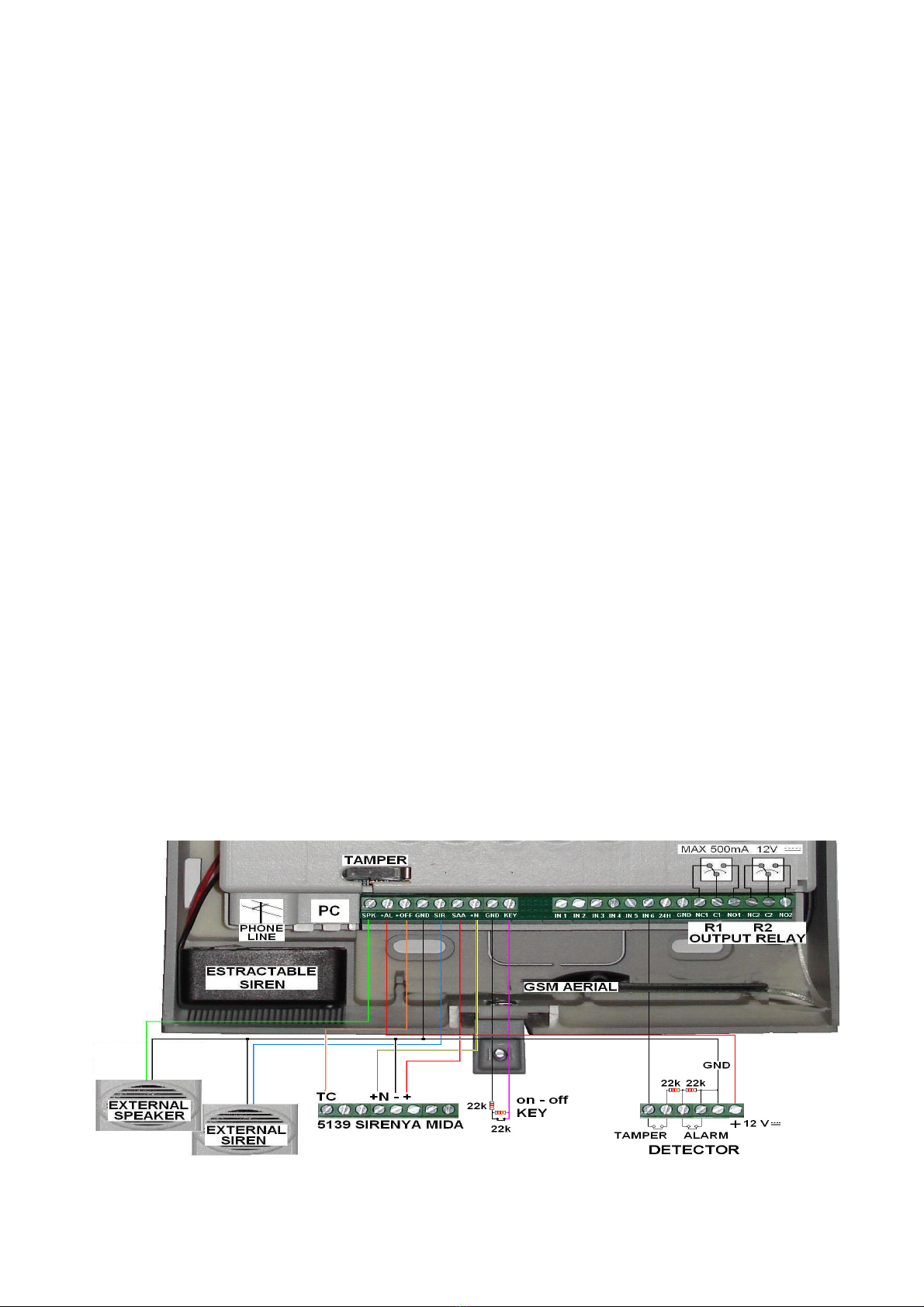
4.5 MAIN TERMINAL BOARD CONNECTIONS
12
4.5.1 SPK TERMINAL
BOARD additional 8 Ohm positive terminal speaker output for control panel’s messages
+ AL
12VDC positive terminal to power max 120 mA hardwired detectors
+ OFF positive polarity terminal when control panel is disarmed - hardwired sirens disabling command
GND (all) ground
SIR +
12V positive terminal max 500mA during alarm for additional sirens
+ SAA 14V positive terminal for hardwired sirens with built-in battery. Note: not available without 230V power supply.
+ N actuated when the positive polarity is disconnected to control hardwired sirens’ alarm.
Caution!
To prevent return signals, you must insert two diodes on the terminal when two sirens are connected.
Caution!
Never use this output to supply power to sirens.
IN 1 - IN 6 double balanced alarm and tamper inputs
24H balanced fault input ( 22K )
KEY double-balanced ON-OFF input for external tag ( closed = OFF)
NC1 -C1- NO1 R1 free changeover relay output - Connect only to SELV circuits (low risk extra low voltage)
NC2 -C2- NO2 R2 free changeover relay output - Connect only to SELV circuits (low risk extra low voltage)
Telephone PSTN telephone line connection
PC Input connector for Silentron PC connecting cable
Caution! Important Notes!
•To comply with the EN 50131 . . standard, you must connect any additional self powered siren with a Tamper protected balanced line
using the alarm inputs.
•The relay outputs must be used within the voltage and power value limits specified in the figure.
•The conventional hardwired detectors that are directly connected to the control panel must be EN . .. compliant, grade 1 or higher and
operate over a balanced lines. You must therefore insert the appropriate resistors as shown (only 3-wire and with a suitable gauge) .
•You have a positive TC signal when the control panel is disarmed in order to disable detectors/sirens fitted with the relevant input.
•The fault input, when used, triggers a FAULT report along with the associated telephone calls.
•All unused inputs can be left with no connection (no need to balance them ), unless they are accidentally closed, even temporarily.Turn
off and on again the device should this occur (reset lines).
4.6 5501-5503 models: TECHNICAL SPECIFICATIONS
4.6.1 5501-5503 models: POWERING WITH ALKALINE BATTERIES (part no. SuperPowerPack 861010)
Output voltage: 9V Maximum available current > 12Ah
4.6.2 Maximum backup power range : battery life depends on the number of installation devices, the number of any other devices of
adjacent installations (within radio range) and the number of operations regularly carried out.
Please find following average battery life in months, taking into account 2 arming and 2 disarming events per day as well as 12 alarms per
year.
ELECTRONIC BOARD FITTED ON BOTH CONTROL PANELS
30151 (5501) - 30153 (5503) boards are fitted with:
•non-reversible plug of 9V power cable for battery pack
•external siren connector
•
You can connect the following to the electronic board:
•1 PC to setup the control panel which is connected using cable part no. 5997 (temporary connection)
•a PSTN telephone jack, with the line connected directly from the outside, or a part no. 5983 board to expand the telephone line within
the premises.
A removable, non-volatile EEPROM, which can be reused to avoid losing data should the control panel be replaced is located in a special
compartment. Your SIM card is to be placed in the other provided compartment (model 5500).
4.6.4 OTHER TECHNICAL SPECIFICATIONS
Power consumption: 180 - 220uA in standby mode - up to 400mA during an alarm with operational GSM - max 200mA with PSTN enabled.
Wireless alarm inputs: up to 99 detectors that may be setup to trigger an immediate or delayed alarm or with AND function for the 3 alarm
zones (A,B,C) or for the 24-hour Panic, Robbery, Technical Alarm zones.
Tamper protection: tamper signal is received from each detector – supervision and low battery signals is received every 28 minutes.
Alarm outputs : 72 -bit encoded digital transmission for "alarm" - "arming" - "partial arming" - "disarming" + 16 control codes.
R.F. fault: constantly monitoring 2 operating frequencies at the same time
Event history log: it stores the last 200 events with the oldest ones being replaced by the newer ones over a non-volatile storage medium.
Alarm time settings: arming delay can be set from 1 to 99 seconds - input delay can be set for each detector and is adjustable from 1 to
45 seconds – general alarm is set to 3 minutes (not adjustable) – adjustable clock operates over 24 hours.
Display: 2x16 character display which allows to identify each external device.

13
Controls: 20-key alphanumeric keypad
Built-in siren: 106 db alarm siren + buzzer with low intensity sound function.
Audio reports/alerts: voice messages for the user and voice prompts guiding the installer.
RF transm./reception: dual band quartz driven with simultaneous operations on both frequencies – factory encoded 72-bit digital codes that
are handled through microprocessor’s self-learning capability – regulation compliant frequency and power.
Radio range : approximately 100m in open air without any background band noise. Device’s positioning within the premises’ structure may
significantly reduce indoor transmission range.
HW connections: PSTN telephone line (also ADSL with appropriate filters)
Telephone section: see 4.7
DIMENSIONS: 307 x 200 x 53mm - WEIGHT: 2.4 Kg - BOX: Byblend - TEMPERATURE: operating/storage -10°/+40°C
4.7 BUILT-IN TELEPHONE TRANSMITTERS - FEATURES
Control panels are fitted with a built-in PSTN (landline) telephone transmitter which complies with ETSI ES 203-21 and R&TTE Standards
and employs the ATS 1 transmission system with emission that complies with EN 61000-6-3 standard. Voice transmission takes 12 seconds
to start and contact-id digital transmission takes 19 seconds. See item 3.9 regarding operating details.
5500 and 5501control panels also feature a built-in a GSM telephone transmitter, which complies with ETSI ES 203-21 & R&TTE
transmission system and employs the ATS1 with emission that complies with EN 61000-6-3 standard. Voice transmission takes 14 seconds
to start and contact-id digital transmission takes 14 seconds. See item 4.9.1 regarding operating details.
See paragraphs 4.8.2 and 4.8.3. to setup numbers and messages and for details regarding their features.
Caution! The GSM module of 5501 model control panel is always turned off for power savings purposes. This module turns on and connects
to the GSM network during an alarm. The time required by the GSM module to turn on varies from area to area and must be added to the
above timings.
4.7.1 PSTN CONNECTION : the external telephone line must necessarily enter directly into the control panel (without inserting any in-
between devices) and be connected through the connector . Should you employ the 5983 board, the external line must be connected to the
input terminals and the downstream devices can be connected to the output terminals .
4.7.2 BUILT-IN GSM MODULE: Telit brand, part no. GE864QuadV2 (Silentron part no. 1002) . This device complies with ETSI ES 203-21
and R & TTE Standards, employing the ATS 2 transmission system with emission that comply with EN 61000-6-3 standards. Voice
transmission takes 12 seconds to start and contact-id digital transmission takes 10 seconds.
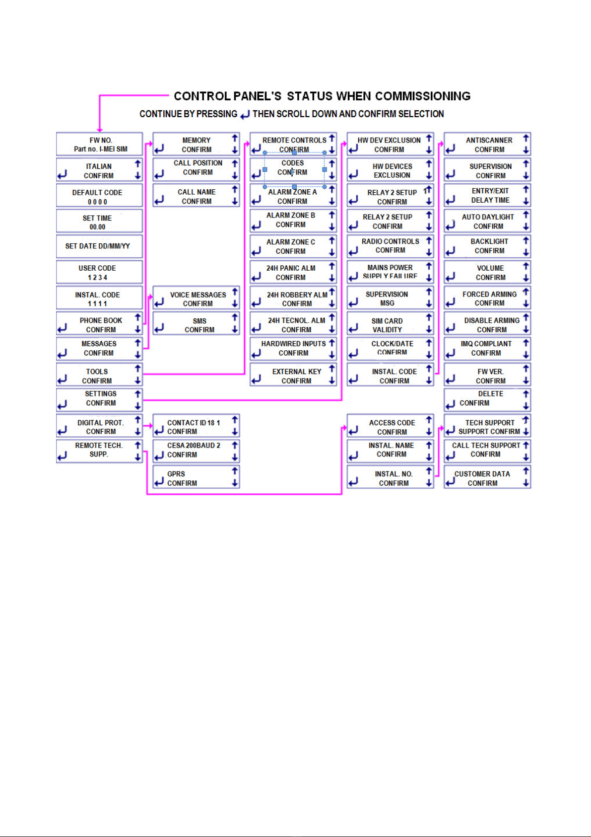
4.8 POWER ON - FIRST INSTALLER ACCESS: all operations are voice guided and any setup is permanent and will not delete by
disconnecting the power. In order to change any setup, it must be edited/deleted or the system must be reset to default settings.
4.8.0 GENERAL ISSUES Models 5500 - 5503 with GSM: you need to insert the SIM card before powering up the control panel .
Caution! You must previously remove the PIN code as well as any messages/phone numbers and any other stored data. The message "!
SIM" will display when there is no SIM card.
Caution! "3G" SIM cards cannot be used as they are not compatible.
Insert battery into the control panel or connect it to the main power supply (ensuring that there are no electric risks).
Continue as shown in the table and display the primary menus and confirm () to access sub menus. Please follow the instructions supplied
in paragraph 4.8.5.20 if you wish to install Silentron’s firmware (not compliant).
Programming errors: should you make a mistake when entering the data, the device will reports the mistake by beeping once or 3 times
(e.g. when setting up remote controls/detectors) .
Caution! You will delete everything that you have setup if you confirm the "CLEAR" option!
Caution! A letter “N” will display top right of some screens. This means that you must enable the required function by switching the N (no) to
Y (yes). The specific function will not operated even if it has been setup without enabling it as above.
4.8.1 SETUP PROCEDURE
We recommend setting up the control panel at the factory, having the different wireless devices forming the system on hand, apart from
sirens. All devices shall then be placed in their suitable positions, after having checked the radio range. The various devices must then be
prepared by opening the battery compartment. Hardwired devices will be setup later Following the order supplied in this manual.
4.8.2 SETTING MESSAGES
Press and hold the key and begin to talk loudly into the control panel’s microphone while enunciating each word to record voice messages.
Remaining seconds to record other messages are displayed during recording. Since count starts at 240 seconds you must record short
messages in order to record multiple recordings (see below).
4.8.2.0 Example of text: WARNING, ALARM IN PROGRESS AT THE SMITHS HOME, Peachtree Rd no. 1 Altanta (pause) DETECTOR . . .
the message will be automatically completed using the "label" (i.e., the position) of the detector that triggered the alarm. Releasing the key
stops the recording and begins its playback. You will then be able to deleted (DELETE) it or approve (ESC) it. Once recording has been
approved, the shows event linking options in the following order:
1) ALL. A, B , C ZONES : alarm message triggered by intrusion detectors setup in the armed zones.
2) TAMPER: alarm message (function is always enabled) triggered by tampering with the system’s equipment.
3) 24H PANIC : alarm message manually enabled by pushing, for example, the yellow button on the remote control.
4) 24H ROBBERY : alarm message manually enabled. We recommended using a specific remote control for this purpose.
5 ) 24H TECHNOLOGIC: alarm message triggered by a technical alarm detector (smoke, water, gas etc.).
6) LOW BATTERY : alarm message identified and triggered by any component of the system.
14
4.8.2.1 POSSIBLE CHANGES TO MESSAGE
Use the keys to change the event options selecting from the above or from one of the following described ones (you will of course need to
record and appropriate message). Since 6 messages are available, you will need to forego using one of the ones below if you wish to select
one of the previous ones.
A ZONE ALARM (only this zone): delete B and C by pressing option 2 and 3 when setting up message 1.
B ZONE ALARM (only this zone): delete A and C by pressing option 1 and 3 when setting up message 1.
C ZONE ALARM (only this zone): delete A and B by pressing option 1 and 2 when setting up message 1.
POWER FAILURE ( 5500-5502 models): sends the message when time set (SETTINGS) to report power failure has elapsed.
SUPERVISION MSG: message is transmitted every 1-25 hours ( SETTINGS).
TEMPERATURE : message is transmitted when the control panel’s temperature reaches over 70°C or falls below 5°C.
FAULT (reported on the display with the text ALERT): a generic message is transmitted which includes 24H input signal, power loss, low
battery, antiscanner, supervision, temperature (< -10°C and> 55°C) and any issue on the PSTN line.
FREE FIELDS - SPECIFIC MSG: the display shows "_ , " .
Possible events are: ALL = alarm; SUPERV= supervision alarm; SCAN = radio interference alarm; ARM = control panel is armed; DISARM =
control panel is disarmed; OPEN = door open; Fblank spaceALL = door has been closed, AR A, AR B, AR C = the specific zone is armed;
NO EVENT: when this selection is confirmed no calls will be associated to the numbers.
Write the event in caps in the first part of the display exactly as described above to setup this function. For example, for “ARMING” write
ARM and confirm with the ↵key. In the second part, write the "label" of the device that triggered the event (see TOOLS ) and confirm with
the ↵key. For the control panel, write CONTROL PANEL.

15
4.8.2.2 VOICE MESSAGE 7 (see 3.8.1 )
If no home automation function are implemented, you only need to record the message concerning how to perform control panel’s remote
operations. Once the command is sent, you will receive a decrypted reply.
- to check the status of the control panel (if it is armed/disarmed), press zero and the pound sign (#).
- to fully arm the control panel, press zero ∗1 #
- to arm only A + B zones, press zero ∗2 #
- to disarm, press zero ∗zero #
If remote home automation functions are scheduled (turning on lights , control of electrical appliances ) message should be recorded
regarding how to execute the commands based on set implementations : see 3.8.4.
Caution! The control panels will not to reply to PSTN landline calls if this message if not recorded. The only ones that will reply are the 5500
model control panels as they always have the GSM line available.
SMS 4.8.2.3 - WRITTEN MESSAGES (only GSM models)
Messages that are useful to the user must be written following the same linking procedure and order. For example:
ALARM SMITHS ATLANTA (up to 24 characters)
4.8.2.4 RESIDENT TECHNICAL SMS
You only need to associate the required telephone number to these messages as they have already been recorded.
1 = low battery control panel caution! System’s operation is about to end!
2 = low battery external device caution! One or more detectors will stop operating shortly (days) !
3 = no supervision and/or radio interference: check event history log
4 = system is armed : this reply message will be transmitted only when the system is armed using a remote phone
5 = system is disarmed: this reply message will be transmitted only when the system is disarmed using a remote phone
6 = 230V AC failure - this message will be transmitted after preset time for mains power supply failure (SETTINGS)
7 = no GSM range for more than 15 min. : this message will be transmitted when the GSM signal is restored
8 = no successful call on PSTN landline: check for any phone line interruption ( landline)
9 = supervision message regarding control panel’s status: a cyclic message transmitted every x number of hours/days (SETTINGS)
10 = SIM expiry warning message: set (SETTINGS) new expiry date when using a prepaid SIM card
11 = 230V mains power supply restored: an automatic message relevant to SMS 6
4.8.2.5 EVENT MESSAGES TRANSMITTED BY THE CONTROL PANEL
Control panels that are not fitted with a voice wizard, require that you record also the messages that they transmit.
Since control panels that feature a voice wizard already have these recordings, their menu is not displayed.
1 Arming System’s total arming
2 Partial arming Arming a section of the system (according to selections)
3 Disarming System's total disarming
4 Door open Warning that a protected door/window is left open
5 External alarm not foreseen for this configuration
6 Pre
-
alarm
sound broadcasted before and alarm
during the preset entry delay
7 Tampering Warning that tampering has occurred to part of the disarmed system
8 New event Warning that if an event has taken place during the last arming period (see event history log)
4.8.3 SETTING PHONE BOOK – UP TO 63 NUMBERS
The control panels call the numbers in the phonebook to transmit their voice messages and SMS when it is required. These numbers must
therefore be set and linked to the different messages to be transmitted during an event. The phone number of each person to be called must
therefore be appropriately associative to the relevant message (see 3.7.2) .
Caution! Key to push to request remaining balance: you must store position 64 of the phone book the number supplied by your SIM card
provider. Remaining balance will be supply by voice message. If the number is setup as follows:123456 #(enter an asterisk at the begging
and the pound symbol at the end of the number), the remaining balance will be sent via SMS to the first number in the phone book when you
press this key on the control panel. The first number must be a cell phone ( the number for the Italian TIM , WIND and Vodafone providers
will be automatically dialed.) You can also ask for the remaining balance by sending an SMS to the control panel with a single question mark.
The control panel will reply to the phone used to send the question mark.
Caution! Silentron is not responsible for any changes made by the SIM card provider which could make some and/or all of the intended
functions unusable, that are implemented based on information that was known when designing the control panel.
The PHONE BOOK menu features three options:
MEMORY: to enter new numbers and link them to the messages
CALL NAME: to search by name and edit a number that has already been stored - simple and intuitive operation.
CALL POSITION: to search by sorting order and edit a number that has already been stored in- simple and intuitive operation.
MEMORY: enter the name and the number of the person to be called following the promps. The message SAVED will display the end of the
procedure. Press to continue, then enter the numbers to associate the voice, sms and technical and sms messages.
Caution! The call will not to be dialed if there are no associated messages.
DIRECT ACCESS N (only GSM models): use to change N into Y (yes) and have the control panel recognize the caller's number over the
GSM line without requiring any code and being enabled to perform any operation.

16
Caution! Telephone line check: in compliance with the standards, the control panel checks the PSTN line and makes calls only when it
properly operates and is not busy. You can disable this function by entering ∗(press ↑) before the number when setting it up in the phone
book to the.
Caution! Pauses between numbers: to insert pauses between numbers being dialed, enter ↓pause) between the numbers.
4.8.4 TOOLS – SETTING EXTERNAL DEVICES
From this menu to setup the additional devices, grouped by type as shown in the " Commissioning " table. The setup of each of devices is
adjustable to allow that each system is configured according to users requirements.
4.8.4.1 REMOTE CONTROLS: up to 32 5524PCK HT handheld transmitters can be setup (over 1 million combinations with rolling code) to
arm/disarm the system and to trigger other functions (1 key is available). Option Remote Control 1 will display when accessing this menu.
Confirm the option. Each remote control can operate on all A, B and C zones to arm (ON) and disarm (OFF) them or only on individual ones.
Press numbers 1 to 6 to disable operations on an individual zone. Excluded zones will stop being displayed and the remote control will
continue to operate using the setup function only on the remain ones.
Setup the remote control as required and wait for the confirmation beep. Press to write the name of the remote control’s user and then
record it locally. By so doing any message that is transmitted and/or any operation that is performed using the remote control will be
recognizable by its name.
4.8.4.2 CODES (up to 32): these are groups of 5 digit codes to arm/ disarm the system using the control panel’s built-in keypad and the/or
other remote locations. The option Code 1 will display when you can access the menu. Confirm the options and perform the same operations
carried out for the remote controls, while also entering a mnemonic code for those who will use it later. DURESS : see 3.6.3. Use to enable
and change N into Y, then continue as above.
4.8.4.3 A (B, C) ALARM ZONE. This allows to setup 3 groups of intrusion detectors that are armed/disarmed at the same time to offer partial
protection . The installer will agree with the customer the most suitable solution.
Up to 99 detectors can be used with the control panel, but please consider that tamper protection , battery check, keypads and sirens
supervision, take up a detector location. For this reason, these functions must be accounted for when calculating and setting up the 99
available positions. The additional items will not trigger intrusion alarms , but only the above functions’ tamper or supervision messages. The
option ALARM ZONE – ALL will display when you access the menu. EXTERNAL: this function cannot be used in order to comply with the
Standard. Press to display the first available detectors/sensors location (SENSOR A01) . Continue by: setting any input delay (button 1,
then enter delay time from 1 to 45 seconds) or setting the AND function (see below). Continue to confirm the prompts when no delay or AND
function is required, until you reach the INSERT BATTERY one. The unit will confirm setup by beeping when the battery is placed into the
setup detector. Caution! Please also read the detector’s programming instructions as some specific setup may need to be performed before
the above. Continue the setup by entering the device’s "label", which is used to identify its position (up to 9 characters - example MAIN
DOOR) and record the voice label.
Caution! If the alarm message was recorded as described in paragraph 4.8.2.0, same will end with . . . DETECTOR . . . You therefore need
to record only “MAIN DOOR” , without having to repeat also the word “detector”.
B and C ALARM ZONES: setup as Zone A .
4.8.4.4 AND Function: two AND function detectors/ sensors can be setup to protect the same environment. The alarm will trigger only when
one of the detectors transmits the alarm signal and the other detector confirms the alarm within 30 seconds. By properly positioning the two
detectors, this feature can greatly reduce that improper alarm are triggered in rough environments (areas with small birds, strong drafts and
other phenomena to which a detector is sensitive). The two AND detectors can be different type ones. Once AND selection is confirmed
(option is not available if a delay has been setup) you will simply need to setup the two devices in sequence.
4.8.4.5 ALARM ZONE 7/24
PANIC ALARM ZONE: you can setup a remote control’s spare key (or another remote control used specifically for this purpose, or a Sensor
HT connected to a button) to immediately enable sirens’ sound. Follow the same previous procedure, but setup the button by pressing and
hold it for 10 seconds when the control panel prompts you to do so.
ROBBERY: by a poket emitter, a keypad or other transmitter, you can transmit silent distress calls (also medical aid ones) following the
previous procedure.
TECHNOLOGIC: Silentron’s product range includes also flooding and fire hazard detectors. You will be able to integrate any other specific
detector made by other manufacturers through the use of a Sensor HT. These devices can be setup for this zone like any other detector (see
4.8.4.3 ).
4.8.4.6 HARDWIRED CONNECTIONS (only 5500-5502 models)
EXTERNAL KEY: an external key can be connected to the control panel (see figure) over a balanced line. In order to comply with the
Standard the key must be tamper protected and certified at least grade 1. Key’s setup is similar to the one for the remote controls .
HARDWIRED ZONES: the six hardwired zones (double balanced - see diagram) are offered subdivided as follows: A+1+2 ; B+3+4; C+5+6.
You can also pair them differently by pressing the 1-2-3 keys when the alarm zone is displayed on the screen. By pressing 4-5-6 the zone
Panic – Robbery and Technical will be displayed. Setup is similar to wireless zones setup, but the AND function is not available.
4.8.5 SETTINGS
This menu is used to define the functional parameters and some operational ones that also the user can access (see par. 3). Caution! Since
in order to comply with the EN 50131 . . standard, some features are mandatory and limited as previously specified, the setting that are not
allowed will not be accepted . Caution! Make sure that you confirm all of the settings.
4.8.5.1 EXCLUDING DETECTORS : this menu allows you to select the operating (SERV) detector/sensor and disable (FSERV) it by
pressing . Repeat the same process to enable detector again.
4.8.5.2 EXCLUDING HARDWIRED DEVICES: follow the same above described procedure.

17
4.8.5.3 SETTING RELAY 1: the relay can be used to control electric loads for home automation, strictly within the features’ listed limits (see
figures) and can be linked with different operations. R1’s default setting is: ON-OFF, bistable operation that switches as a result of the ON
command and returns still with an OFF command sent over the telephone. If associated with internal clock’s operation , telephone switching
will bypass clock setting. R1 can also be used in the following other modes:
•PULSE : it switches for the preset time (adjustable from 0 to 999 seconds) following a telephone control or by internal clock setting.
•GENERAL ALARM : it switches for the time set for any type of alarm, apart from the antiscanner one.
•TAMPER: it switches for 3 minutes in the event of a tamper alarm
•24H PANIC/ROBBERY/ TECHNOLOGIC: it switches for 15 seconds in the event of a Panic/ Robbery/Technologic alarm.
•FAULT: it switches for 15 seconds in the event of low batteries (control panel & detectors) , no supervision, radio noises during arm
condition (antiscanner), absence of GSM field (5500 model) .
•ARM/DISARM : it switches when the system is armed and returns when it is disarmed (useful to connect an on-off LED)
•ENT. DELAY: it switches during the entry delay set for one or more detectors.
4.8.5.4 SETTING RELAY 2: the relay can be used to control electric loads for home automation, strictly within the features’ listed limits (see
figures) and can be linked with different operations. R2’s default setting is: GENERAL ALARM which means that it switches for 3 minutes in
the event of an alarm. Apart from not being enabled by the clock, this relay can be used like R1.
4.8.5.5 WIRELESS CONTROLS (this function is not compliant) : you can enable local automation functions by calling the control panel
over the phone. The control panels feature 16 wireless transmissions to enable Silentron’s receivers. These receivers will in turn switch on
lights and handle home automation functions and electric utilities. To operate controlled by the control panel, they must memorize one of the
above RADIO CONTROLS. Confirm pulse command or change it to an on/off command (↑↓) and then prepare the receiver. Press ↵to setup
(see receiver’s instructions).
Caution! In order to facilitate user operations over the phone, you must prepare a good guiding message (see 4.6.1) for this function.
4.8.5.6 GSM/LANDLINE (only 5500-5501 models): select outside calls priority ( ↑↓) . Should a primary telephone line fault take place, the
other means of communication will automatically take over.
4.8.5.7 POWER FAILURE (only 5500-5502 models): this function is always enabled (Y= yes) in compliance with the Standard. Follow the
voice instructions to receive this SMS alert after the preset time (adjustable from 1 to 60 minutes).
4.8.5.8 SUPERVISION MSG : this function is always enabled (Y= yes) in compliance with the Standard. Enter the message transmission
period (pursuant to the Standard, from 1 to 25 hours), then enter count start time.
4.8.5.9 SIM CARD EXPIRATION : press ↑↓to change N (no) into Y (yes) to enable the function. Enter SIM card’s expiration date in months,
leaving at least one month to spare.
4.8.5.10 CLOCK/DATE: it is important that the internal clock and the date are updated to log events properly in the alarm history log.
Internal clock - accuracy : the adopted technical solutions involve up to a 2 seconds margin of error per day. As foreseen by EN 50131
standard, the clock should be adjusted if required during regular system maintenance.
4.8.5.11 INSTALLER CODE: this useful function allows you to display/edit this code. You will need to open the control panel (which will
trigger a tamper alarm), disconnect power and battery, restore power after a few seconds and access setup using the default installer code
should code be forgotten. This operation does not involve settings loss.
4.8.5.12 ANTISCANNER : this function is always enabled (Y= yes) in compliance with the Standard. The panel checks the transmitted radio
signals and reports those that interfere with operations. You can set negligible interference time in seconds (1-60) , after which the control
panel’s built-in siren will begin to sound and power is supplied to SIR terminal for 30 seconds (5500-5502 models). You can also assign a
voice or text message or one of the relays to this function if required.
4.8.5.13 SUPERVISION: this function is always enabled (Y= yes) in compliance with the Standard. Supervision signal is transmission by
each device about every 28 minutes. A FAULT message will display when the system is armed/disarmed should signals no longer be
received by one or more devices. Arming will be disabled, even if only a single signal is missing during the 60 minutes prior to arming. You
can also assign a voice or text message or one of the relays to this function if required.
4.8.5.14 EXIT/ENTRY DELAY: Caution! Do not set an extremely short delay since it will not allow for the support transmissions that take
place during this time. The Standard allows for a time that is adjustable from 1 to 99 seconds.
4.8.5.15 DAYLIGHT SAVING MODE: this function is enabled by default. Press ↑↓for locations where daylight saving time does not apply.
4.8.5.16 BACKLIGHT: Enable this function (only 5500 and 5502 models) . Use the ↑↓keys to change N (no) into Y (yes) and keep backlight
always on. Caution! Backlight turns off when there is no mains power supply.
Models 5501 and 5503: with default setting the display turns off after 60 seconds of inactivity.
4.8.5.17 VOLUME: use the ↑↓keys to adjust audio volume.
4.8.5.18 FORCED ARMING: use the ↑↓keys to change N (no) into Y (yes) and enable this function to fully or partially arm the system at a
preset times ( see 3.6.4 ) . Disarming will be performed manually.
4.8.5.19 ARMING DISABLED: this function is always enable and cannot be changed (Y = yes) in order to comply with the Standard.
4.8.5.20 EN 50131 COMPLIANT: control panels are supplied with IMQ compliant firmware (it complies with EN 50131 .. ). Use the ↑↓keys
to change N (no) into Y (yes) if you wish to use Silentron’s firmware.

18
4.8.5.21 FIRMWARE VERS. : this option displays the firmware version currently used by control panel. (required for any upgrades).
4.8.5.22 DELETE: if you confirm () the text message “DELETE?”, you will be deleting all settings and the events stored in the event history
log. Be careful about confirming the operation as it is not reversible.
4.9 DIGITAL PROTOCOLS
The control panels feature two types of the most commonly used digital protocols in the security fields. Data can be sent to 2 +2 telephone
numbers over the phone network and can also be transmitted to two different monitoring stations. The control panels also transmit the
alarms over the GPRS line (IP) in SIA protocol. Select the required protocol or mode when you access this menu, then continue as follows.
4.9.1 CONTACT ID / CESA 200 BAUD: enter customer identification , the primary and secondary phone number (if in shortage, press ) to
transmit to, select between the direct or inverse mode (↑↓) and then enable by changing N into Y (↑↓). At this point setup the messages
that are to be transmitted having previously agreed about which ones to use with the receiving monitoring station.
Advanced settings : you can enter from 1 to 4 additional specific events to be sent in the CODEV field. You must enter the event type in the
first section ( i.e. ALL) and device’s label or its position in the second section (e.g. A03 – enter CENTRALE for the control panel). At this point
the control panel will display the code that will be sent.
You can edit the code displayed by the control panel for the CONTACT ID protocol, while the one for CESA 200 protocol is not editable (96
for CODEV1, 97 for CODEV2, 98 for CODEV3, 99 for CODEV4, etc.).
CONTACT ID example:
CODEV1 1 130 01 003
ALL , A03
After having entered the ALL event () and the device’s position A03 (), the code associated with
the event that will be transmitted by CONTACT ID protocol is displayed in the first line. You can
confirm the code using or edit it using ←).
Advanced programming also allows you to enter the detector’s label replacing its location. For example, if you have associated the
"KITCHEN" label for detector A03 you will have:
CODEV1 1 130 01 003
ALL , KITCHEN
After entering the ALL event () and the detector’s label "KITCHEN" ( ) , the code associated
with the event which will be transmitted by the CONTACT ID protocol will display in the first line.
You can press to confirm it or edit the code using (←).
CESA 200 BAUD example:
CODEV1 96
ALL , A03
After having entered the ALL event () and the device’s position A03 (), the code associated
with the event that will be transmitted by CESA 200 protocol is displayed in the first line. Press
to confirm the code.
You can select between one of the following listed events and the devices must have been previously set. Please ensure that you enter the
exact data allowing the control panel to appropriate associate it.
EVENTS MEANING EXT. DEVICE MEANING
ALL Alarm A01 – A99 A zone detectors
F ALL Alarm end B01 – B99 B zone detectors
C01 – C99 C zone detectors
TAMPER Tamper P01 – P99 24H PANIC alm zone detectors
SUPERV Supervision failure R01 – R99 24H ROBBERY alm zone detectors
SCAN Radio interference T01 – T99 24H TECHNOL zone detectors
BATT Low battery HW A1 – A2 A zone hardwired detectors
EVENTS MEANING EXT. DEVICE MEANING
OPEN Open door while arming HW B1 – B2 B zone hardwired detectors
ARM Total arming HW C1 – C2 C zone hardwired detectors
ARM A Arming A zone HW A A zone hardwired tamper
ARM B Arming B zone HW B B zone hardwired tamper
ARM C Arming C zone HW C C zone hardwired tamper
ARM AB Arming AB zone TEL01 – TEL32 Remote controls
ARM AC Arming AC zone COD01 – COD32 Keypads codes
ARM BC Arming BC zone HW KEY Key input
DISARM Disarm CONTROL PANEL Panel
4.9.2 TESTING DIGITAL TRANSMISSION
When the control panel is disarmed, you can send a TEST event to a monitoring station as described in 3.5.1 - 3.5.2. Confirm TEST DIALER
option, enter the phone number of the monitoring station to call and select the type of message to send (CONTACT ID or CESA 200),
confirming the prompts displayed on screen.
You must setup the digital protocol that will be used to transmit in order to send dialer TEST to a monitoring station. The code transmitted for
CONTACT ID protocol is 602, while the one for CESA is 90.

19
4.9.3 TABLE OF DIGITAL PROTOCOLS CODES
EVENT CONTACT ID CESA 200 CESA 200
A ZONE ALARM 1 130 01 001/099 1 14/22 detectors from 01 to 09 1 23 detectors from 10 to 09
A ZONE ALLARM END 3 130 01 001/099 1 14/22 detectors from 01 to 09 1 23 detectors from 10 to 09
A ZONE HARDWIRED ALARM 1 130 01 101/102 1 24/25 detectors 01 and 02
A ZONE HARDWIRED ALLARM END 3 130 01 101/102 2 24/25 detectors 01 and 02
ALARM ZONE A 1 130 02 001/099 1 26/34 detectors from 01 to 09 1 35 detectors from 10 to 09
B ZONE ALARM END 3 130 02 001/099 1 26/34 detectors from 01 to 09 1 35 detectors from 10 to 09
B ZONE HARDWIRED ALARM 1 130 02 103/104 1 36/37 detectors 01 and 02
B ZONE HARDWIRED ALARM END 3 130 02 103/104 2 36/37 detectors 01 and 02
C ZONE ALARM 1 130 03 001/099 1 38/46 detectors from 01 to 09 2 47 detectors from 10 to 09
C ZONE ALARM END 3 130 03 001/099 1 38/46 detectors from 01 to 09 2 47 detectors from 10 to 09
C ZONE HARDWIRED ALARM 1 130 03 105/106 1 48/49 detectors 01 and 02
C ZONE HARDWIRED ALARM END 3 130 03 105/106 2 48/49 detectors 01 and 02
24H PANIC ALARM 1 123 04 001/099 1 55/58 detectors from 01 to 04 1 59 detectors from 05 to 99
24H ROBBERY ALARM 1 122 05 001/099 1 50/53 detectors from 01 to 04 1 54 detectors from 05 to 09
24H TECHNICAL ALARM 1 150 06 001/099 1 61/88 detectors from 01 to 28 1 89 detectors from 29 to 99
TAMPER CONTROL PANEL 1 137 00 000 1 94
TAMPER ZONE A 1 137 01 001/099 1 12
TAMPER HARDWIRED A ZONE 1 137 01 000 1 12
TAMPER B ZONE 1 137 02 001/099 1 12
TAMPER HARDWIRED B ZONE 1 137 02 000 1 12
TAMPER C ZONE 1 137 03 001/099 1 12
TAMPER HARDWIRED C ZONE 1 137 03 000 1 12
TAMPER 24H PANIC ZONE 1 137 04 001/099 1 12
EVENT CONTACT ID CESA 200 CESA 200
TAMPER 24H ROBBERY ZONE 1 137 05 001/009 1 12
TAMPER 24H TECNOLOGIC ZONE 1 137 06 001/009 1 12
ARM WITH USER CODE 1 401 00 000 1 60
DISARM WITH USER CODE 3 401 00 000 2 60
ARM WITH REMOTE CONTROLS 1 401 00 001/032 1 60
DISARM WITH REMOTE CONTROLS 3 401 00 001/032 2 60
ENTER CODES 1 401 00 033/064 1 60
DISARM CODES 3 401 00 033/064 2 60
ARM WITH EXTERNAL KEY 1 409 00 000 1 60
DISARM WITH EXTERNAL KEY 3 409 00 000 2 60
ARM WITH REMOTE PHONE 1 407 00 000 1 60
DISARM WITH REMOTE PHONE 3 407 00 000 2 60
BATTERY CONTROL PANEL 1 302 00 000 1 91
CONTROL PANEL BATTERY RESTORED 3 302 00 000 2 91
BATTERY EXTERNAL DEVICES 1 384 01/06 001/099 1 13
BATTERY EXTERNAL DEVICES
RESTORED 3 384 01/06 001/099 2 13
MAINS POWER SUPPLY FAILURE 1 301 00 000 1 92
MAINS POWER RESTORED 3 301 00 000 2 92
SUPERVISION CALL 1 602 00 000 1 90
NO SUPERVISION ZONE A, B, C, T 1 381 00 000 1 11
SCANNER 1 344 00 000 1 95
OPEN WHILE ARMED ZONE A, B, C 1 371 01/03 001/099 N.A.
4.9.4 GPRS : fill out required fields as follows:
INTERNET DATA
APN: Ask your SIM card’s provider the APN to be employed for GPRS data connections.
IP: data is not currently required for TIM, WIND, and VODAFONE SIM cards. Ask your provider for this data should you be using
another type of SIM card.
USER: data is not currently required for TIM, WIND, and VODAFONE SIM cards. Ask your provider for this data should you be using
another type of SIM card.
PSW: data is not currently required for TIM, WIND, and VODAFONE SIM cards. Ask your provider for this data should you be using
another type of SIM card.

20
GPRS 1-2 / SIA protocol 1-2 (first and second connection option - same procedure) – MONITORING STATION DATA Menu
USER ID Enter the 4 digit number assigned for the central monitoring station.
TCP/UDP
MODE
Select operating mode (
) and confirm (
)
IP ADDRESS enter the IP address of the monitoring station.
IP PORT enter the IP port of the monitoring station.
BACK
-
UP SMS NO
enter the number of the central monitoring sta
tion
to send an SMS
when
transmission
is
fault
(GPRS 1
-
2 only).
SUPERV. CHECK enter the time between two transmission checks in minutes
REVERSE COUNT N by default, select operating mode () and confirm ( )
EVENTS Menu see 4.9.1 and enable the required events
4.10 REMOTE TECHNICAL SUPPORT (ADVANCED SETTINGS – WITHOUT VOICE WIZARD)
Installer must install device 5996 Teleservice to in order to provide the remote technical support service. This unit must be connected to the
telephone line and this option must be setup in the control panel. This option will enable user to directly connect with the service over the
landline by pressing the "wrench" icon or, should user be out of the premises, to enable installer’s remote connection (see 3.4.4.).
You must setup the following fields to enable the remote technical support service.
ACCESS CODE: this code will enable the control panel to connect to the remote support service(see 3.4.4 ).
INSTALLER NAME : 24 characters are available.
INSTALLER NUMBER: enter the phone number that the control panel should call.
CUSTOMER SERVICE: this is a second number that Silentron makes available upon request to allow the system to be directly connected
with the Silentron Service Centre (available during office hours) . To connect it needs to scroll down to the CALL option.
CUSTOMER DATA: enter your name, address, city and phone number. Complete by pressing ESC
5 MANAGEMENT OVER PC: Caution! All operations performed over the PC require an account with administrative privileges.
The operation that you can perform locally over a PC that is suitably connected using a 5997 cable are similar to those carried out with the
remote technical support service since both functions use the same software. Please find below a summary of the operations. For detailed
information, please see THE REMOTE TECHNICAL SUPPORT SERVICE instructions.
Operations Summary
Silenya HT control panels: display the "Control Panel Sheet" or the "System Sheet" to identify and read all system’s parameters. Make/edit
all control panel’s settings over the PC.
5529 Touch-screen HT Keypad: download the wireless and hardwired detector’s "labels" (System Sheet) by connecting the control panel
to the PC. After having connected a 5529 Touch-screen HT Keypad to your PC you will be able to enter these labels (write data) to edit them
with additional characters for an enhanced usability.
Setup Procedure. Use the 5997 special connecting cable supplied with the CD containing the cable’s drivers and Silbox software. Since the
cable’s driver and the software must be installed on your PC, you must install them and then connect the PC and the control panel using the
5997 cable. When you run the software, the language selection menu is displayed, followed by an image screen displaying the following
buttons on the top:
Click the SETUP CONNECTION option and select the required connection (TTL/USB control board or keypad). This connection does not
require a password: confirm by clicking OK. Click CONNECT to connect to the control panel.
Read data: click "Read Data " to download the control panel’s data sheet bearing the current date and time. The sheet can be saved to your
PC and/or printed (as PDF or on paper).
Remote Keypad: click "Remote Keypad" to display the same screen displayed on the control panel which will allow you to perform all
operations by clicking on the displayed buttons as you would directly from the control panel’s keypad. By clicking “Read Data” after having
edited any settings, you will be able to download the updated control panel’s data sheet bearing the date and time of the update.
Data sheet: this option allows you to display, open and/or delete the sheets.
Manage Control Panel: this option brings you back to the control panel after having performed other operations.
This manual suits for next models
4
Table of contents
Other SILENTRON Control Panel manuals


Popular Control Panel manuals by other brands


Frymaster
Frymaster M2000 Operation manual

Matrix Switch Corporation
Matrix Switch Corporation MSC-CP32X1E product manual

Proteco
Proteco Q80A instruction manual

DMP Electronics
DMP Electronics XR150 series installation guide

CBE
CBE PC320-ST user manual

DMP Electronics
DMP Electronics PC0128 installation guide


