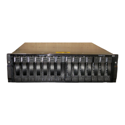
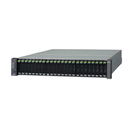
Silicon Graphics InfiniteStorage 120 User manual

007-4853-001
SGI®InfiniteStorage™ 120
Mass Storage Hardware Topics
Edition -001

Proprietary Rights Notices
COPYRIGHT
© 2006, Silicon Graphics, Inc. All rights reserved; provided portions may be copyright in third
parties, as indicated elsewhere herein. No permission is granted to copy, distribute, or create
derivative works from the contents of this electronic documentation in any manner, in whole or in
part, without the prior written permission of Silicon Graphics, Inc.
LIMITED RIGHTS LEGEND
Use, duplication, or disclosure by the Government is subject to restrictions as set forth in the Rights
in Data clause at FAR 52.227-14 and/or in similar or successor clauses in the FAR, or in the DOD,
DOE or NASA FAR Supplements. Unpublished rights reserved under the Copyright Laws of the
United States. Contractor/manufacturer is Silicon Graphics, Inc., 1500 Crittenden Lane, Mountain
View, CA 94043.
TRADEMARKS AND ATTRIBUTIONS
Silicon Graphics, SGI, and the SGI logo are registered trademarks, and InfiniteStorage is a
trademark, of Silicon Graphics, Inc., in the United States and/or other countries worldwide.
Linux is a registered trademark of Linus Torvalds. All other trademarks mentioned herein are the
property of their respective owners.
Document Description
007-4853-001
This document will remain the official reference source for all revisions and releases of this
product until rescinded by an update.
Disclaimer
It is the policy of Silicon Graphics Inc. to improve products as new technology, components,
software, and firmware become available. SGI reserves the right to make changes to any products
herein at any time without notice. All features, functions, and operations described herein may not
be marketed in all parts of the world.

SGI InfiniteStorage 120 i
Contents
Drive Module Description........................................................................................................... 2
Components Accessed From the Front of the Module .......................................................... 2
Components Accessed From the Rear of the Module............................................................ 2
Drive Module Specifications....................................................................................................... 3
Drive Module Status LEDs .................................................................................................... 3
Environmental Specifications ..................................................................................................... 5
ESM Canisters............................................................................................................................. 7
Redundancy............................................................................................................................ 7
Connections............................................................................................................................ 7
ESM Lights ............................................................................................................................ 8
Environmental Services Monitor Performance Specifications ................................................. 10
Power-Fan Canisters ................................................................................................................. 11
Redundancy.......................................................................................................................... 11
Power-Fan Canister Lights................................................................................................... 12
Disk Drives................................................................................................................................ 13
Disk Drive Lights................................................................................................................. 14
Hot Swap ................................................................................................................................... 16
Drive Module Replacement Parts ............................................................................................. 17
Tools and Equipment ............................................................................................................... 18
Turning On the Power to the Drive Module ............................................................................. 19
Turning Off the Power to the Drive Module............................................................................. 20
Installing SAS Cables................................................................................................................ 22
Removing the Components from the Drive Module................................................................. 23
Reinstalling the Components in the Drive Module ................................................................... 26
Replacing a Failed Environmental Services Monitor ............................................................... 28
Replacing a Failed Power-Fan Canister .................................................................................... 31
Replacing a Failed Disk Drive .................................................................................................. 34


SGI InfiniteStorage 120 iii
List of Figures
Figure 1. SGI InfiniteStorage 120 Drive Module .................................................................... 1
Figure 2. Drive Module – Front View ...................................................................................... 2
Figure 3. Drive Module – Rear View ........................................................................................ 2
Figure 4. Drive Module Status LED Locations ....................................................................... 4
Figure 5. Service for the ESM Canister is from the Rear of the Drive Module ........................ 7
Figure 6. SAS Pinouts on SGI Host System I/O Port ............................................................... 8
Figure 7. SAS Connectors on an ESM ...................................................................................... 8
Figure 8. ESM Lights ................................................................................................................ 8
Figure 9. Service for the Power-Fan Canister is from the Rear of the Drive Module ............ 11
Figure 10. Power-Fan Canister Lights .................................................................................... 12
Figure 11. Service for the Disk Drive is from the Front of the Module ................................. 13
Figure 12. Disk Drive Numbering .......................................................................................... 13
Figure 13. Disk Drive Lights .................................................................................................. 14
Figure 14. Power Switches on a Drive Module ...................................................................... 19
Figure 15. Drive Active Light Must be Turned Off Before Turning Off the Power .............. 20
Figure 16. Power Switches on a Drive Module ...................................................................... 21
Figure 17. SAS Cabling Example ........................................................................................... 22
Figure 18. Removing a Disk Drive ......................................................................................... 24
Figure 19. Removing a Power-Fan Canister ........................................................................... 24
Figure 20. Removing an ESM ................................................................................................. 25
Figure 21. Reinstalling a Disk Drive ....................................................................................... 26
Figure 22. Reinstalling a Power-Fan Canister ........................................................................ 27
Figure 23. Replacing an ESM ................................................................................................. 27
Figure 24. ESM Fault Light .................................................................................................... 28
Figure 25. Removing an ESM ................................................................................................. 29
Figure 26. ESM Lights ............................................................................................................ 29
Figure 27. Fault Light and Power Switch on a Power-Fan Canister ....................................... 31
Figure 28. Power Switches on a Drive Module ...................................................................... 31
Figure 29. Removing a Power-Fan Canister ........................................................................... 32

SGI InfiniteStorage 120 v
List of Tables
Table 1. Specifications for the Drive Module ........................................................................... 3
Table 2. Temperature and Humidity ........................................................................................ 5
Table 3. Altitude ........................................................................................................................ 5
Table 4. Shock and Vibration .................................................................................................... 5
Table 5. ESM Lights ................................................................................................................. 9
Table 6. Performance Specifications for the ESMs ................................................................ 10
Table 7. Power-Fan Canister Lights ........................................................................................ 12
Table 8. Disk Drive Ports ........................................................................................................ 14
Table 9. Disk Drive Lights ...................................................................................................... 15
Table 10. Disk Drive State Represented by Lights ................................................................. 15


. . . . . . . . . . . . . . . . . . . . . . . . . . . . . . . . . . . . . . . . . . . . . . . . . . . . . . . . . . . . . . . . . . . . . . . . . . . . .
1
InfiniteStorage 120 Hardware Topics
This document is a collection of hardware topics that describe the SGI InfiniteStorage 120
drive module.
Figure 1 SGI InfiniteStorage 120 Drive Module
This document provides:
•Descriptions of the drive module
•Drive module specifications
•Descriptions of the environmental services monitor (ESM) canister
•Descriptions of the power-fan canister
•Descriptions of the disk drives
•Procedures related to drive module maintenance

InfiniteStorage 120 Hardware Topics . . . . . . . . . . . . . . . . . . . . . . . . . . . . . . . . . . . . . . . . . . . . . . . .
2
Drive Module Description
A drive module provides storage capacity. The environmental services monitors (ESMs)
in the drive module connect to a host. A drive module contains disk drives, ESMs, fans,
and power supplies.
Figure 2 shows the front of the drive module, and Figure 3 shows the rear of the drive
module. The figures show the following components:
Components Accessed From the Front of the Module
•Bezel – A plastic-molded frame
•Drives – Twelve removable disk drives
Components Accessed From the Rear of the Module
•ESM canisters– Two removable canisters that contain the ESMs
•Power-fan canisters– Two removable canisters that contain the power supplies and
cooling fans
Figure 2 Drive Module – Front View
1. Bezel
2. Disk Drives
Figure 3 Drive Module – Rear View
1. ESM Canisters
2. Power-Fan Canisters

. . . . . . . . . . . . . . . . . . . . . . . . . . . . . . . . . . . . . . . . . . . . . . . . . . . . . . . Drive Module Specifications
3
Drive Module Specifications
The following table lists the physical and electrical specifications for the drive module.
Table 1 Specifications for the Drive Module
Drive Module Status LEDs
Each drive module is equipped with four enclosure summary LEDs. These are stacked
internally on the far-left side of the enclosure and are visible at the front of the unit (see
Figure 4 on page 4).
The LEDs (top to bottom) have the following color and functional descriptions:
•Amber - when lit, this LED indicates that a component within the module has failed.
•Amber - when lit, environmental temperatures have exceeded functional tolerances.
•White - this LED is reserved for future functional uses.
•Green - shows that +5V power to the module is on.
Item Specification
Dimension Height: 8.8 cm (3.5 in.) with rails (2U); width: 44.7 cm
(17.6 in.); depth: 51.4 cm (20.3 in.)
Weight Empty: 14 kg (32 lb); fully loaded: 24.6 kg (54.3 lb)
Input voltage 100–240 V
Input frequency 50 or 60 Hz (nominal)
Steady-state maximum current At 240 V: 1.9 A; at 100 V: 3.9 A
Standby current 0.21 A at 240 V, 60 Hz; 0.15 A at 100 V, 50 Hz

InfiniteStorage 120 Hardware Topics . . . . . . . . . . . . . . . . . . . . . . . . . . . . . . . . . . . . . . . . . . . . . . . .
4
Figure 4 Drive Module Status LED Locations

. . . . . . . . . . . . . . . . . . . . . . . . . . . . . . . . . . . . . . . . . . . . . . . . . . . . . . Environmental Specifications
5
Environmental Specifications
The following tables list the temperature, humidity, altitude, shock, and vibration
specifications for the drive module.
Table 2 Temperature and Humidity
Table 3 Altitude
Table 4 Shock and Vibration
Condition Parameter Specification
Temperature1Operating range 10°C to 40°C (50°F to 104°F)
Maximum rate of change 10°C (18°F) per hour
Storage range –10°C to 65°C (14°F to 149°F)
Maximum rate of change 15°C (27°F) per hour
Transit change –40°C to 65°C (–40°F to 149°F)
Maximum rate of change 20°C (36°F) per hour
Relative humidity (noncondensing) Operating range 20% to 80% (noncondensing)
Storage range 10% to 90%
Transit range 5% to 95%
Maximum dew point 26°C (79°F)
Maximum gradient 10% per hour
1If you plan to operate a system at an altitude between 1000 m to 3000 m (3280 ft to 9842 ft) above sea level, lower
the environmental temperature 1.7°C (3.3°F) for every 1000 m (3280 ft) above sea level.
Environment Specification
Operating 30.5 m (100 ft) below sea level to 3000 m (9842 ft) above sea level
Storage 30.5 m (100 ft) below sea level to 3000 m (9842 ft) above sea level
Transit 30.5 m (100 ft) below sea level to 12,000 m (40,000 ft) above sea level
Condition Parameter Specification
Vibration Operating 5-500-5 Hz, 0.25 g sinusoidal, 2
octave per minute, 3 axis
Nonoperating (unpacked) 5-500-5 Hz, 1.0 g sinusoidal, 2 octave
per minute, 3 axis
Transit and storage (packed) 5-500-5 Hz, 2.0 g sinusoidal, 2 octave
per minute, 3 axis

InfiniteStorage 120 Hardware Topics . . . . . . . . . . . . . . . . . . . . . . . . . . . . . . . . . . . . . . . . . . . . . . . .
6
Shock Operating (no damage) 5-g peak acceleration, 11 ms
duration, 1/2 sine pulse, 3 axis
Nonoperating (unpacked) 25-g peak acceleration, 11 ms
duration, 1/2 sine pulse, 3 axis
Transit and storage (packed) 30-g peak acceleration, 11 ms
duration, 1/2 sine pulse, 3 axis
Condition Parameter Specification

. . . . . . . . . . . . . . . . . . . . . . . . . . . . . . . . . . . . . . . . . . . . . . . . . . . . . . . . . . . . . . . . . ESM Canisters
7
ESM Canisters
An environmental services monitor (ESM) provides the interface between the disk drives
in a drive module and the hosts. The hosts connect directly to the ESMs. Each drive
module contains two ESM canisters.
Figure 5 shows an ESM canister that is being inserted into the rear of a drive module.
Figure 5 Service for the ESM Canister is from the Rear of the Drive Module
Redundancy
When a drive module contains two ESMs, if one ESM fails, the other ESM will provide a
data path to the disk drives. You can replace a failed redundant ESM while the power to
the drive module is turned on and the drive module is processing data.
Connections
The ESM attaches to the host using SAS cables. The ESM has two SAS connectors.
•SAS-in – Used for cables from the host to the ESM.
•SAS-out – Not used.
Figure 6 shows the SAS pinout connections on the SGI host system’s standard I/O port.
Figure 6 SAS Pinouts on SGI Host System I/O Port
Figure 7 shows the SAS connectors on an ESM.
Pin 1
Pin 8

InfiniteStorage 120 Hardware Topics . . . . . . . . . . . . . . . . . . . . . . . . . . . . . . . . . . . . . . . . . . . . . . . .
8
Figure 7 SAS Connectors on an ESM
1. SAS-In Connector
2. SAS-Out Connector
ESM Lights
Figure 8 shows the ESM’s lights.
Figure 8 ESM Lights
Table 5 describes the lighting patterns.
Table 5 ESM Lights
Location Light Color On Off
1a
a.The amber LED also comes on when connecting cable HSSDC2 to MiniSAS (2 lanes to 4 lanes).
ESM Link Fault Amber A link error occurred. No errors have occurred.
2 ESM Link Green The link is active. A link error occurred.
3 Service Indicator Blue This light is not used; however, it blinks during power-on
initialization.
4 Fault Amber A fault exists within the ESM. Normal condition.
5 Power Green Power is present. No power is applied.

. . . . . . . . . . . . . . . . . . . . . . . . . . . . . Environmental Services Monitor Performance Specifications
9
Environmental Services Monitor Performance
Specifications
The following table lists important performance specifications for each ESM in a drive
module.
Table 6 Performance Specifications for the ESMs
Item Specification
Data transfer to disk drive 3 Gb/s
Maximum number of disk drives 12 in each drive module

InfiniteStorage 120 Hardware Topics . . . . . . . . . . . . . . . . . . . . . . . . . . . . . . . . . . . . . . . . . . . . . . . .
10
Power-Fan Canisters
The power-fan canister, with an integrated cooling fan, is a replaceable canister within a
drive module.
Each drive module contains two power-fan canisters. The power-fan canister converts
incoming AC power to DC power. The fan circulates air inside the module by pulling air
in through the vents on the front of the canister and pushing air out of the vents on the
back of each fan.
Figure 9 shows a power-fan canister that is being inserted into the rear of a drive module.
Figure 9 Service for the Power-Fan Canister is from the Rear of the Drive Module
1. Power Supply A
2. ESM A
3. Power Supply B
4. ESM B
Redundancy
Because each drive module contains two power-fan canisters, if one power-fan canister is
turned off or malfunctions, the other power-fan canister can maintain electrical power to
the drive module.
Likewise, each power-fan canister contains two fans. The fans provide redundant cooling.
If one of the fans in either power-fan canister fails, the remaining fans will continue to
provide sufficient cooling to operate the drive module.
Each power-fan canister uses a 2-meter (6.56 ft.) power cord for connection to the rack’s
power distribution unit (PDU) or wall outlet.

. . . . . . . . . . . . . . . . . . . . . . . . . . . . . . . . . . . . . . . . . . . . . . . . . . . . . . . . . . . . Power-Fan Canisters
11
Power-Fan Canister Lights
Figure 10 shows the power-fan canister’s lights.
Figure 10 Power-Fan Canister Lights
Table 7 describes the lighting patterns.
Table 7 Power-Fan Canister Lights
Location Light Color On Off
1 DC Power Green DC power from the power-fan
canister is available.
DC power from the power-fan
canister is not available.
2 Service Indicator Blue This light is not used; however, it blinks during power-on
initialization.
3 Fault Amber A fault exists within the
power-fan canister.
Normal condition.
4 Power Green Power is present. Power is not present.
DC AC
1 2 3 4 Power on
Switch
AC Input

InfiniteStorage 120 Hardware Topics . . . . . . . . . . . . . . . . . . . . . . . . . . . . . . . . . . . . . . . . . . . . . . . .
12
Disk Drives
The disk drives store user data. A disk drive has three components: a hard drive, a hard
drive carrier, and an adapter card for connecting the disk drive to the midplane. The disk
drives are replaceable components.
Each drive module contains 12 disk drives. The disk drives are Serial Attached SCSI (SAS)
disk drives.
Access to the disk drives is from the front of the drive module. Figure 11 shows a disk
drive that is being inserted into a drive module.
NOTE The disk drives in your module might differ in appearance from those shown
here. The variation does not affect their function.
Figure 11 Service for the Disk Drive is from the Front of the Module
The physical locations of the disk drives are numbered 1 through 12, from left to right and
top to bottom. Figure 12 shows the disk drive numbering.
Figure 12 Disk Drive Numbering
Each disk drive has two ports. Each port has a separate number. Having two ports enables
both ESMs to access a drive through the different port numbers. Table 8 lists the disk
drives and the port number each ESM uses for a disk drive.
Table of contents
Other Silicon Graphics Network Storage Server manuals


