Siliken SE3.3Ni User manual

Siliken Electronics S.L. Ronda Isaac Peral y Caballero,14 - Parque Tecnológico E-469 0 Paterna - Valencia - Spain
Phone: (+34) 902 41 22 33 - Fax.: (+34) 96 070 92 65 [email protected] - www.silikenelectronics.com
SE3.3Ni - 3. Ni - 4.6Ni
Date: 05/10/2010
Single-phase power grid-connected inverters
User's manual

SILIKEN appreciates your support for our products.
We recommend that you read this instruction manual carefully in its entirely before handling the Inverter.

users manual inverter SE3.3Ni - SE3. Ni - SE4.6Ni
Safety
SAVE THESE INSTRUCTIONS This manual contains important instructions of models SE3.3Ni, SE3. Ni & SE4.6Ni that shall be followed
during installation, application and maintenance of the PV inverter.
Safety Precautions/Safety Notes
Only training-qualified personnel are allowed to perform the electrical installation, wiring, opening and repair of the SE inverters. Even if no
external voltage is present, the SE inverters may still contain high voltage and the risk of electrical shock.
The temperature of the heat sinks outside of the device could exceed 70°C (15 °F) in normal operation. There is the risk of burn injury by
inadvertent contact.
The following general safety precautions must be observed during all phases of operation, service, installation and repair of this device. Failure
to comply with these precautions or with specific warnings elsewhere in this manual violates safety standards of design, manufacture, and
intended use of the device. The manufacturer assumes no liability for the customers failure to comply with these requirements.
Safety Sym ols
To reduce the risk of injury and to ensure the continued safe operation of this product, the following safety instructions and warnings are marked
in this manual.
!
Warning, risk of electric shock
Presents safety information to
prevent injury or death to users
and/or installers.
Caution (refer to accompanying
documents)
Presents information to prevent damage
to this product.
Earthground symbol

users manual inverter SE3.3Ni - SE3. Ni - SE4.6Ni
General Safety Precautions
Training-qualified personnel are allowed to mount, reconfigure or repair this PV inverter. Also, licensed electricians are allowed to install and
inspect the permanently-wired system.
Remove all conductive jewelry or personal equipment prior to installation or service of the device, parts, connectors, and/or wirings.
Ensure there is no grounding path through the human body. Well-insulated guards, e.g. insulated mat or shoes, are necessary when working
the operating device.
Use safety guard against risks of electrical shock or personal injury by any sudden component failure.
Follow the instructions manual and all information on cautions or warnings must be adhered to.
Use proper lifting techniques when handling enclosure, equipment or parts.
The list does not contain all measures pertinent to the safe operation of the device. If special problems arise which are not described in
sufficient detail for the purposes of the buyer, contact your specialized dealer or technician.
Safety Installation and Operation
Installation of the device must be in accordance with the relevant electrical installations stipulated by local distribution network operator (DNO).
Correct grounding, short-circuit and/or overcurrent protection must be provided to ensure operational safety.
Read all instructions and cautionary remarks in the manual before installation.
Switch off the circuit breakers before installation. Keep dry when working the inverter.
It energizes when the PV arrays are exposed to light. Cover the arrays with opaque (dark) material before installation.
Check both AC and DC connections with a digital voltmeter prior to any installation or removal procedures.
Install the inverter out of direct sunlight.
Risk of electrical shock may be contained even if no external voltage is present.
Allow at least 5 minutes for the inverter to discharge completely after disconnecting the AC and DC sources from the inverter.

users manual inverter SE3.3Ni - SE3. Ni - SE4.6Ni
The temperature on the external heat sink may be high in normal operation and cause skin burn injury when touched. Pay attention to high
temperature components.
Prevent the risk of fire hazard, do not cover or obstruct the heat sink.
Allow modification in your electrical system to be carried out only by the training-qualified electricians.
Repair and Maintenance
The SE inverter contains no user serviceable parts. Only personnel trained and authorized by SILIKEN ELECTRONICS are allowed to carry
out internal repair and maintenance of the unit. Please return the device for overhaul if some fault is caused.
WARNING!
Not to make alterations or use tampering assembly in the inverter without manufacturers authorization unless specified elsewhere
in this Manual. They may result in injury, electric shock, or fire and void the warranty.
Wiring the inverter
Input/Output Terminals: Use wire size #10 AWG to #6 AWG, 90°C (194°F) Copper Wire.
Reconfirm all connections and screws have been made correctly and tightened properly.
WARNING!
All electrical installation and the wiring methods shall be done according to the relevant electrical installations stipulated by local
distribution network operator (DNO) and should follow the important safety instructions in this manual.
Connection of the AC ca le
WARNING!
Reconfirm the circuit breaker connected to the main utility is switched OFF before connecting the power cable from the breaker
to the AC connector.

users manual inverter SE3.3Ni - SE3. Ni - SE4.6Ni
Connection of the DC ca le
CAUTION!
Identify the different polarity of DC voltage on each PV string and connect respectively to the input terminals. Make sure the DC
voltage that PV arrays generate is equal to or less than 500 VDC in any case.
WARNING!
Route the DC connection cables to the SE inverters away from any possible hazards that could damage the cables.
WARNING!
Hazardous voltage is still present on the device after disconnection of all PV DC inputs. Allow five (5) minutes for the inverter to
discharge the energy stored in capacitors completely.
WARNING!
PV arrays will be energized when exposed to light. Cover the arrays with opaque (dark) materials during installation and wiring.
!

Introduction
1.1 General
1.2 Specifications
1.3 Accessories
Installation
2.1 Placement
2.2 Mounting
2.3 Wiring the Inverter
2.3.1 Connection of the AC cable
2.3.2 Connection of the DC cable
2.3.3 Connection of the communication cable
2.4 Wiring Inverter in Parallel
Operation
3.1 Overview
3.2 Operation Feature
3.3 LED Indication
3.4 LCD Display
.......................................................................................................................
...................................................................................................................
.........................................................................................................
.............................................................................................................
.........................................................................................................................
..............................................................................................................
.................................................................................................................
...................................................................................................
..........................................................................
..........................................................................
.......................................................
.......................................................................................
...........................................................................................................................
.................................................................................................................
..................................................................................................
........................................................................................................
............................................................................................................
1
2
3
9
10
11
11
12
15
16
1
20
26
2
2
29
31
35
Table of Contents
users manual inverter SE3.3Ni - SE3. Ni - SE4.6Ni

Table of Contents
users manual inverter SE3.3Ni - SE3. Ni - SE4.6Ni
3.6 Communication
3.7 Explanations of Error Messages
Warranty Information
Technical Documentation
5.1 Outline Drawing
5.2 Technical Specifications
5.3 Efficiency
5.4 De-Rating Operation
........................................................................................................
..............................................................................
.........................................................................................................
..................................................................................................
........................................................................................................
...........................................................................................
..................................................................................................................
................................................................................................
4
5
44
44
47
50
50
51
52
53

Introduction
8
1.1 General
The SE Inverters product family is a series of grid-connected photovoltaic inverters with FLEX-MPPTs that is a method for flexible MPPTs
management. SE inverters utilize the FLEX-MPPTs technology to efficiently absorb more energy from the PV panels. The SE Inverter is
designed to convert DC power produced by photovoltaic arrays to AC voltage that is then fed into the 230V/50Hz or 230V/60Hz mains utility.
The SE family currently contains three (3) members which are SE4.6NI, SE3. NI and SE3.3NI. The overview of the grid-tied solar energy
system with a three (3) panel strings inverter is shown in Figure 1.1.1. SE inverters comply with all VDEW (Association of German Electricity
Producers) regulations for supplementary grid feeding to low voltage electricity grid of the utility. Additionally, SE inverters are also certified to
comply with the latest regulations of the DIN VDE 0126-1-1 and the according harmonized standards and the low voltage regulations described
in the CE declaration.
The SE inverter is designed to support up to three (3) PV strings and operate automatically without any configuration once it is installed and
commissioned according to the technical specifications. When at least one of the DC input voltages generated by the photovoltaic module
goes above the minimum MPP voltage setting and under the pre-set threshold value, the embedded controller is then waked up and goes
through the system check mode and then stay at monitoring mode because the pre-set threshold value is not reached yet. At this time, the
SE inverter would not feed the AC power to the mains utility; instead, it keeps watching the input DC voltage. Once the input DC voltage goes
up above the pre-set threshold value and all other conditions necessary for grid connection are checked and fulfilled for a certain period of
time, the SE inverter goes into the grid feeding mode that turns the AC relays on and begins feeding the AC voltage into the grid steadily. When
all of the input DC voltages fall below the minimum MPP voltage setting which is 100Vdc, the SE inverter will then shut itself down. The SE
inverter will be waked up automatically when one or more of the input DC voltages go up above the minimum MPP voltage setting.
It is very much appreciated that you choose Siliken SE inverters as your power conversion devices in the solar power system. This document
contains the information you need for the installation and settings of the SE inverters. Therefore, it is strongly recommended to read this manual
carefully before the SE inverter installations and settings.
users manual inverter SE3.3Ni - SE3. Ni - SE4.6Ni

Introduction
9
users manual inverter SE3.3Ni - SE3. Ni - SE4.6Ni
Fig. 1.1.1 Grid Connected Solar System Overview
1.2 Specifications
100-450 V
DC
500 V
DC
Maximum DC power
MPP Voltage range
Maximum voltage range
Maximum current
Number of MPPTs
Maximum number of Strings
DC Input
4,5 kWp 5 kWp
20 A (2x10A)
SE3.3Ni SE3. Ni SE4.6Ni
6 kWp
20 A (2x10A) 30 A (3x10A)
1-2 1-2 1-3
22 3
AC Output
Nominal power
Maximum power
Maximum effective current
Nominal voltage
Nominal frequency
Harmonic distortion (THD)
Power factor
Galvanic insulation
Number of phases
3,3 kW
3, kW
16,52 A
3, kW
4,4 kW
19,13 A
230 VAC
50 Hz
<3%
>0,99
Assured by RCMU*
Single phase
4,6 kW
5,1 kW
22 A
SE3.3Ni SE3. Ni SE4.6Ni
General characteristics
IP 65
<1 W
Forced ventilation
LED / LCD
RS232C / RS4 5
5 0 x 422 x 1 2 mm.
-20ºC to +55ºC (without derating)
Maximum 95%
MC4
RST25i3
22,5 Kg. 23 Kg.
Yield maximum
Yield UE
Level of protection
Own consumption (stand by)
Cooling system
Display
Comunications
Dimensions
Weight
Operating temperature
Ambient humidity
Type of DC connection
Type of AC connection
SE3.3Ni SE3. Ni SE4.6Ni
22,5 Kg.
96,3%
95,1% 95,1% 95,4%
96,3% 96,2%
Utility Grid
Load
SE Inverter
String A
String B
String C
Fuse box
º¾
Ä
Ê

Introduction
10
users manual inverter SE3.3Ni - SE3. Ni - SE4.6Ni
1.3 Accessories
Operation Manual 1 pc
AC Connector 1 pc
RJ-45 plug 2 pcs
DC Connector Sealing Cap (female) 1 pc
DC Connector Sealing Cap (male) 1 pc
CE Marking.
Electrical Safety Directive EN 5017 .
Electromagnetic Compatibility Directive.
EN 61000-6-4: EN 55011
EN 61000-6-2: EN 61000-4-2
EN 61000-4-4
Complies with RD 661/2007, RD 1663/2000, DK 5940 and VDE 0126-1-1.
Standards
Due to our continuous improvement policy, these specifications are subject to change without prior notice.
Anti-island protection.
Protection against leakage currents.
Protection against reverse polarity.
Protection against short circuits.
Protections
* RCMU: Residual Current Monitoring Unit.

Installation
11
users manual inverter SE3.3Ni - SE3. Ni - SE4.6Ni
2.1 Placement
1. SE inverters may be located indoors or outdoors, according to protection class
IP65.
2. Avoid mounting the inverter on a location where is directly exposed to rains.
3. Leave at least 50 cm of free space above and below the inverter for better ventilation
(see Figure 2.1.1).
4. Mount the inverter on a wall that shall be firm enough to sustain the inverter with
30Kg in weight.
5. Avoid mounting the inverter on a location directly exposed to the sunshine to keep
the ambient temperature of the inverter within -20ºC and 55 ºC.
WARNING!
Some parts of the cooling surface can reach temperature over
70ºC. Keep the flamma le and explosive materials an appropriate
distance away from the inverter!
WARNING!
Do not expose the inverter to the corrosive liquids and/or gases.
6. Humidity shall be within 0% and 95%.
7. Keep DC wiring as short as possible to minimize power loss.
. Mount bracket should be fastened on a concrete or a masonry wall with the
accessory anchors.
Fig. 2.1.1 Clearances required for SE inverter installation
wall

2.2 Mounting
There are five main steps to mount the inverter on the wall:
1. First, loosen the two (2) side screws and take the bracket apart from the inverter as shown in the figure 2.2.1 below.
2. Use the mount bracket (Fig 2.2.2) as a template to mark the locations where holes shall be drilled. The holes shall be 50 mm depth into
the wall with diameter of mm.
Installation
12
users manual inverter SE3.3Ni - SE3. Ni - SE4.6Ni
Fig. 2.2.1 Remove side screws and racket
Fig. 2.2.2 Mount racket
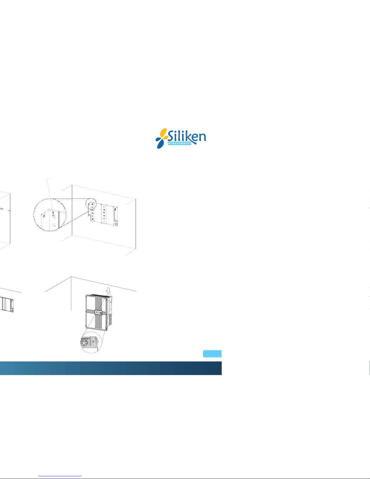
3. After drill the holes, the mount bracket is then held against the wall and fastened on the wall with the anchors as shown in Figure 2.2.3.
4. Once the mount bracket is fastened, the inverter may be lifted up and hooked onto the bracket as shown in Figure 2.2.4.
Installation
13
users manual inverter SE3.3Ni - SE3. Ni - SE4.6Ni
Fig. 2.2.3 Fasten the mount racket
Fig. 2.2.4 Hooking inverter onto the racket
60
80-150
The height of the anchor head < mm
Installation
14
users manual inverter SE3.3Ni - SE3. Ni - SE4.6Ni
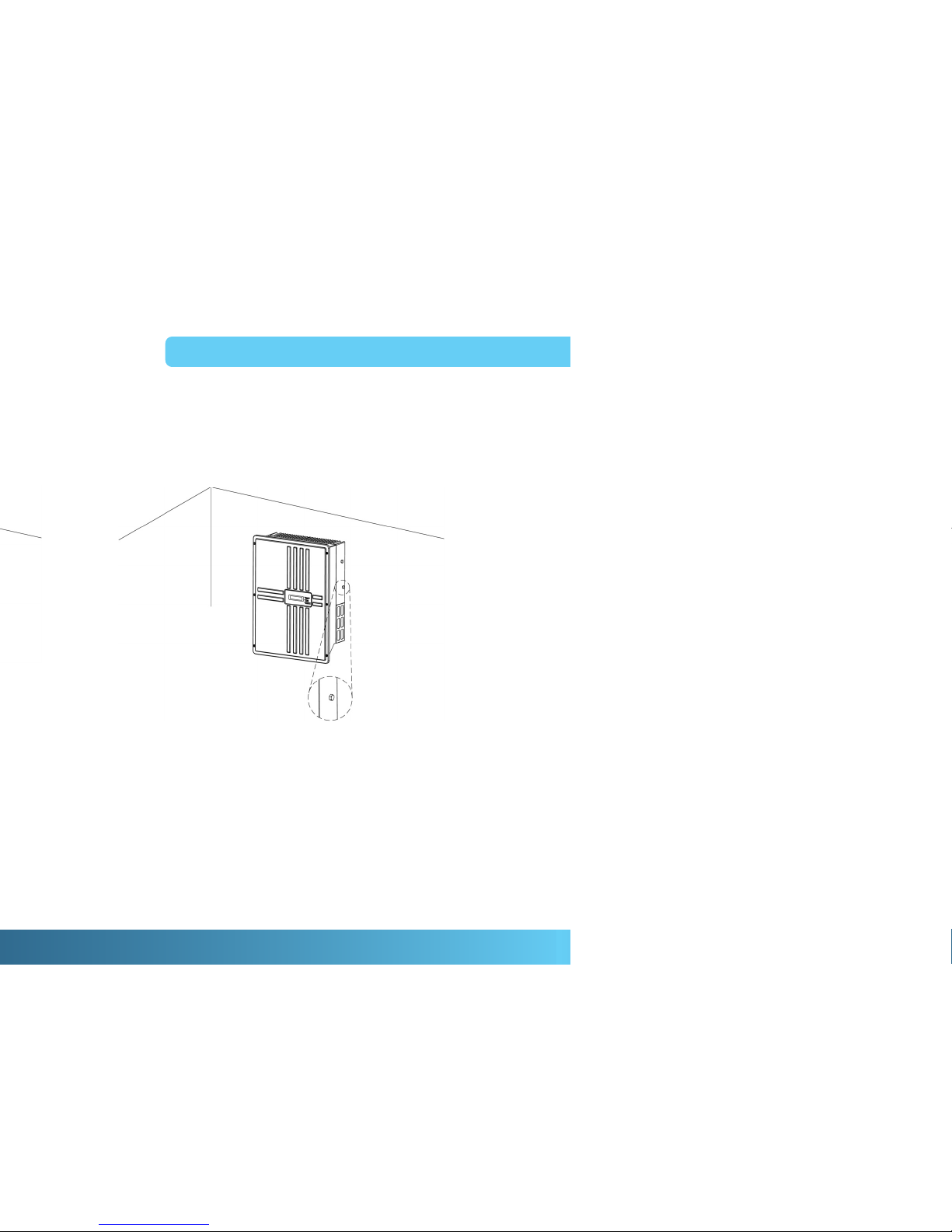
5. After the inverter is hooked on the bracket, it needs to fasten the inverter on the bracket with two side screws (see Figure 2.2.5) to prevent
the inverter from pulling away from the bracket.
Fig. 2.2.5 Fasten the inverter with two side screws

Installation
15
users manual inverter SE3.3Ni - SE3. Ni - SE4.6Ni
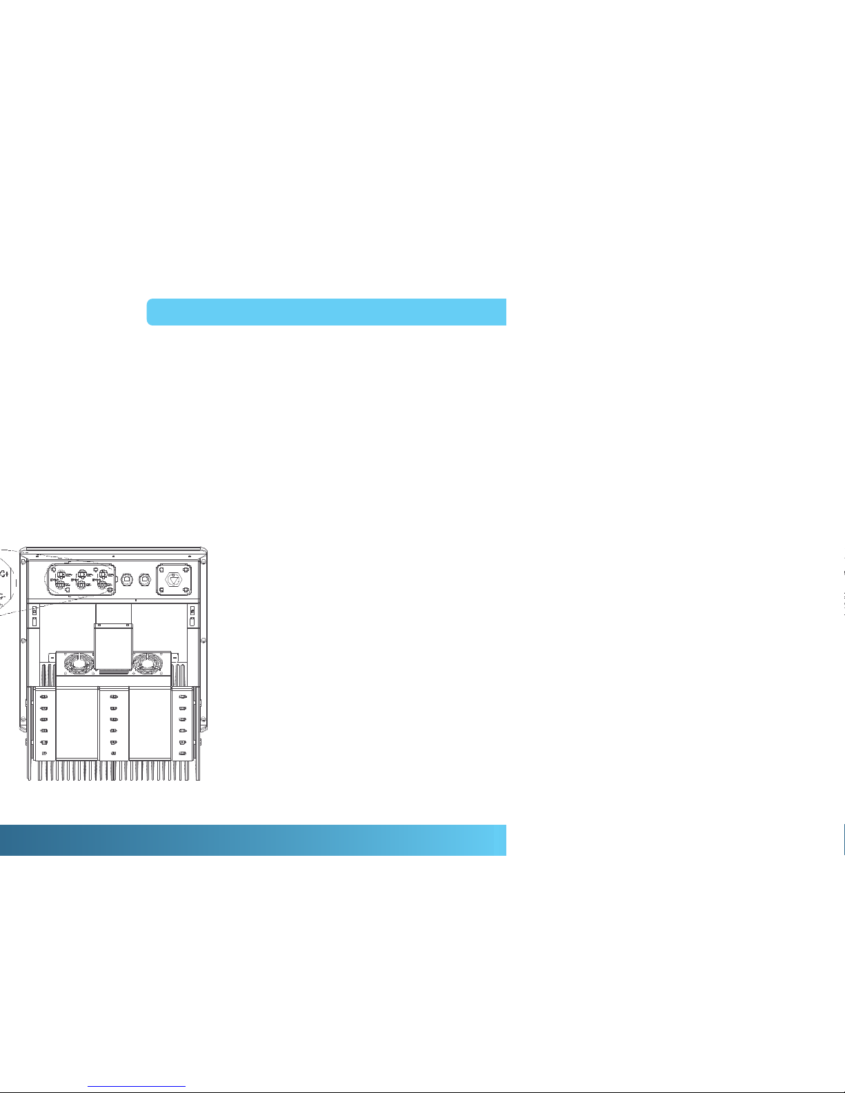
2.3 Wiring the inverter
The following three sections describe the connections of wirings for the AC, DC, and communication ports. SE4.6NI has three (3) pairs of DC
connection terminals, string A, B, and C, while SE4.6Ni, SE3. Ni and SE3.3Ni have only two (2) pairs of DC connection terminals, string A
and C. All three models have two (2) RJ-45 connectors, and one (1) AC connection terminal on the bottom of the inverter shown in the Figure
2.3.1 and Figure 2.3.2. DC connection terminals are used to connect to PV strings through circuit breakers that shall be placed close to the
inverter. RJ-45 connectors are used for external communication to a remote computer or terminal. AC connection terminal is used to connect
to the mains utility through a circuit breaker that shall be closed to the distribution panel. Each pair of the DC connection terminals shall be
connected to one PV string with the maximum rating listed in section 1.2. It is recommended to supply 350 VDC to each string although the
MPP voltage range is within 100 VDC and 450 VDC.
Fig 2.3.1 Wiring compartment front view Fig 2.3.2 Wiring compartment ottom view
String A String B String C Communication
Port
AC Output
pulg
String A String B String C
Communication
Port AC Output
pulg

Installation
16
users manual inverter SE3.3Ni - SE3. Ni - SE4.6Ni
WARNING!
All electrical work shall be done in accordance with the local and national electrical codes and should follow the important safety
instructions in this manual.
WARNING!
Make sure that you use suitable connecting cables for both the AC and DC wirings. The cable must be adequately dimensioned
and suitably inert to temperature fluctuation, UV radiation and other possible hazards.
2.3.1 Connection of the AC ca le
1. Open the Fuse Box and switch off the circuit breaker used to connect the inverter to the grid.
WARNING
Reconfirm that the circuit breaker to the main utility is switched OFF before connect the power cable from the breaker to the AC
connector.
2. Use the AC connector that was included in the shipping package to connect the AC power cable as illustrated in the figure 2.3.1.1 and figure
2.3.1.2.
Fig 2.3.1.1. Assem ly of the AC ca le
and the AC connector.

Installation
17
users manual inverter SE3.3Ni - SE3. Ni - SE4.6Ni
Fig. 2.3.1.2 Assem ly of the AC ca le and the AC connector
CAUTION!
To ensure that the total impedance of the grid plus the interconnection AC power cable shall be less than 1.25 .
1. The AC connector is suitable for cables with a cross-section of up to 4 mm2.
2. Connect the cable GND to the screw labeled of the AC connector
3. Connect the cable N to the screw labeled N of the AC connector.
4. Connect the cable L to the screw labeled L of the AC connector.
5. Tighten the screws with a torque of 0.9Nm.
WARNING!
Each connection to a SE inverter must be installed with a separate circuit breaker with 25A type B. No other appliances may be
connected to the circuit breaker.
6. Reconfirm that all connections have been performed properly as described above and all screws are properly tightened.
7. Plug the AC connector into the AC terminal to complete AC cable connection for the inverter.
Installation
18
users manual inverter SE3.3Ni - SE3. Ni - SE4.6Ni
2.3.2 Connection of the DC ca le
There are three models of the SE inverters. The SE4.6NI is designed to support up to three (3) independent PV strings, string A, B, and C,
while SE3. NI and SE3.3NI are made to support up to two (2) PV strings, string A and C.
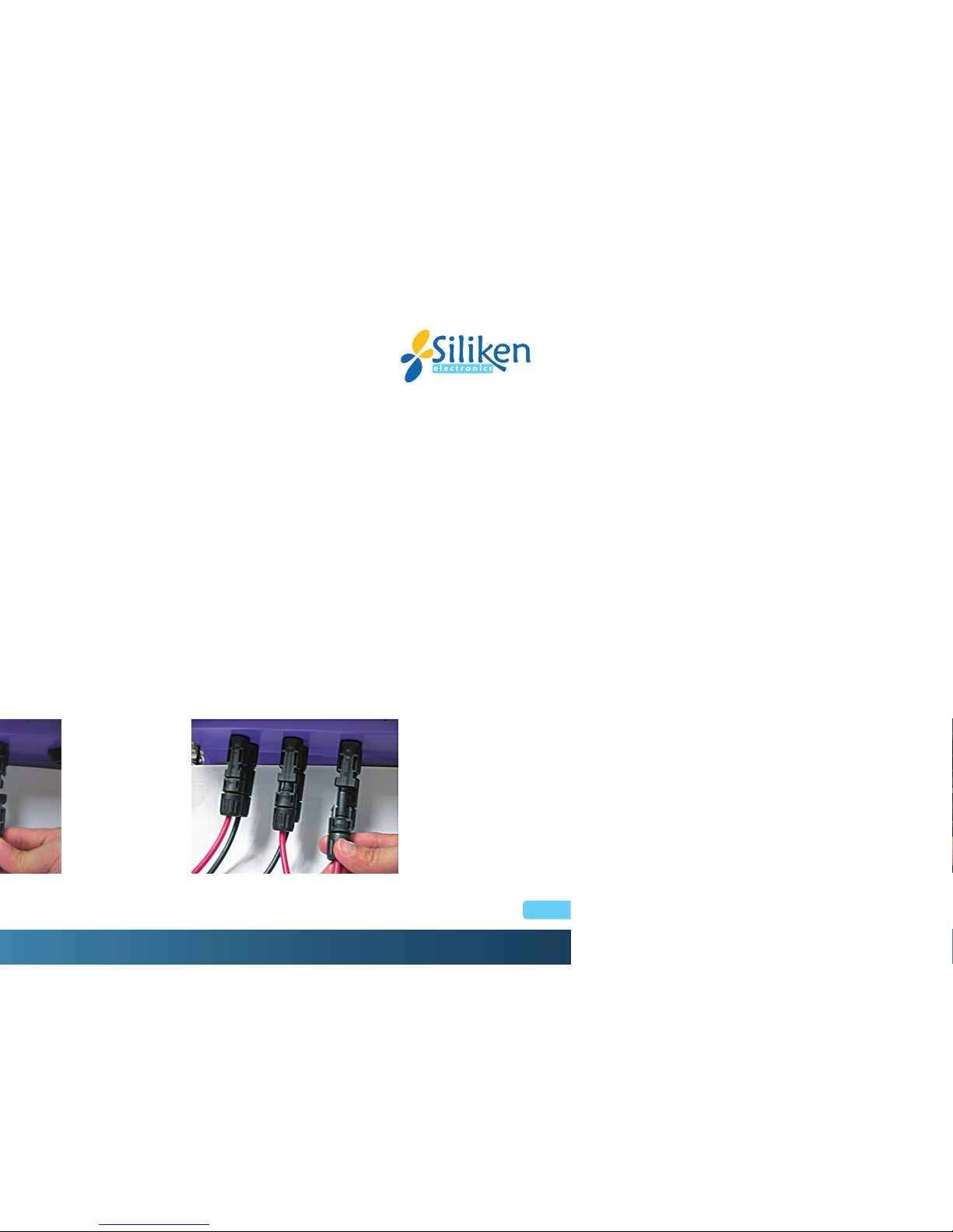
Each PV string shall provide a DC input voltage with maximum power of 4500W and maximum current of 10A. There are two (2) terminals,
labeled + and -, per DC voltage input located on the bottom of the inverter used for the DC cable connections, shown in Figure 2.3.2.1,
Figure 2.3.2.2 and Figure 2.3.2.3.
Fig. 2.3.2.1 DC terminals for DC ca le connection
Installation
19
users manual inverter SE3.3Ni - SE3. Ni - SE4.6Ni
CAUTION!
Polarities of each DC input voltage from a PV string shall be precisely correctly connected to the + (positive) and (negative)
terminals of a pair respectively. The DC voltage must be less than 500V in any condition.
The + cable of the DC input voltage shall be connected to the terminal labeled + and the - cable of the DC input voltage shall be connected
to the terminal labeled -.
WARNING!
Route the DC connection cables to the SE inverters away from any possible hazards that could damage the cables.
WARNING!
Hazardous voltage is still present on the device after disconnection of all PV DC inputs. Allow 5 minutes for the inverter to discharge
the energy completely.
!
Fig. 2.3.2.2 PV- terminal connection Fig. 2.3.2.3 PV+ terminal connection
This manual suits for next models
2
Table of contents
Other Siliken Inverter manuals

Popular Inverter manuals by other brands

MidNite
MidNite MNBCM Installation

Siemens
Siemens MICROMASTER Vector Series operating instructions

Doosan
Doosan 9/270 Operation and maintenance manual

Master Battery
Master Battery MasterPower Beta Series Installation and operation manual

JFY tech
JFY tech JSI-1100TL Installation and operator's manual

Sunforce
Sunforce 200Watt POWER INVERTER user manual

Goodwe
Goodwe GW8000-MS Quick installation guide

Samlexpower
Samlexpower SAM-1500C-12 owner's manual

LONCIN
LONCIN 3000i owner's manual

Deye
Deye SUN-3K-G06 user manual

Invertek Drives
Invertek Drives Optidrive Plus 3GV Compact user guide

Champion Global Power Equipment
Champion Global Power Equipment 201110 quick start guide


