ALAT UJI PTT 2000 User manual

Mountz, Inc
ISO 9001 (2000) company
PTT
PTT
Portable Torque Tester
Operating Instructions
2000

Features
System Accuracy +/- 0.5% of reading from 20% to 100% of full scale.
System Accuracy +/- 1% of reading from 10% to 20% of full scale.
Recommended for all hand screwdrivers, wrenches or power tools.
Provides “EZ-Plug & Play” with Mountz Transducers. Features “ARCII” technology, an instant auto-recognition
system of the transducer connected to the PTT.
Selection of six operating modes: (Track, Peak, First Peak, Audit, Torque + Angle, and Tool Test).
Seven units of torque measurements: (ozf.in, lbf.in, lbf.ft, cN.m, N.m, kgf.m, kgf.cm).
Features built-in Tool Tests operation.
Includes two PC Windows based software programs:
PTT Interface Program- for sensor calibrations, meter calibration and tool tests,
PTT Bootloader - for updating the PTT operating systems.
Mountz Statics Calculator - for SPC, CP & CPK calculations.
“Flash" memory allows upgrades to be done by the user in the field & internet through the USB port.
Five low-pass filter selections (3000, 2000, 1500, 500 and 200 Hz).
Easy to use Menu Structure.
Real Time Clock for time stamping of readings.
Six-digit display.
USB interface to download readings to PC.
High Capacity Li-Ion Batteries for long life (30 hrs with standard transducers and 16 hrs with brushless rotary).
Can connect to most mv/v transducers and can store calibration data for up to 50 non smart torque sensors.
The 5VDC capability allows unit to be used with a Brushless Rotary Transducer for testing pulse tools and high
RPM tools.
Torque and Angle readings are displayed simultaneously and supports up to 8000 RPM.
Stores a total of 2500 data points.
Real time graph of torque vs. time using associated PC Windows software.
Features a Buzzer and Go / No Go LEDs that illuminate when high or low setting is achieved.
Display Accuracy is better than +/- 0.0625 of reading.
Page 1
Heading Page
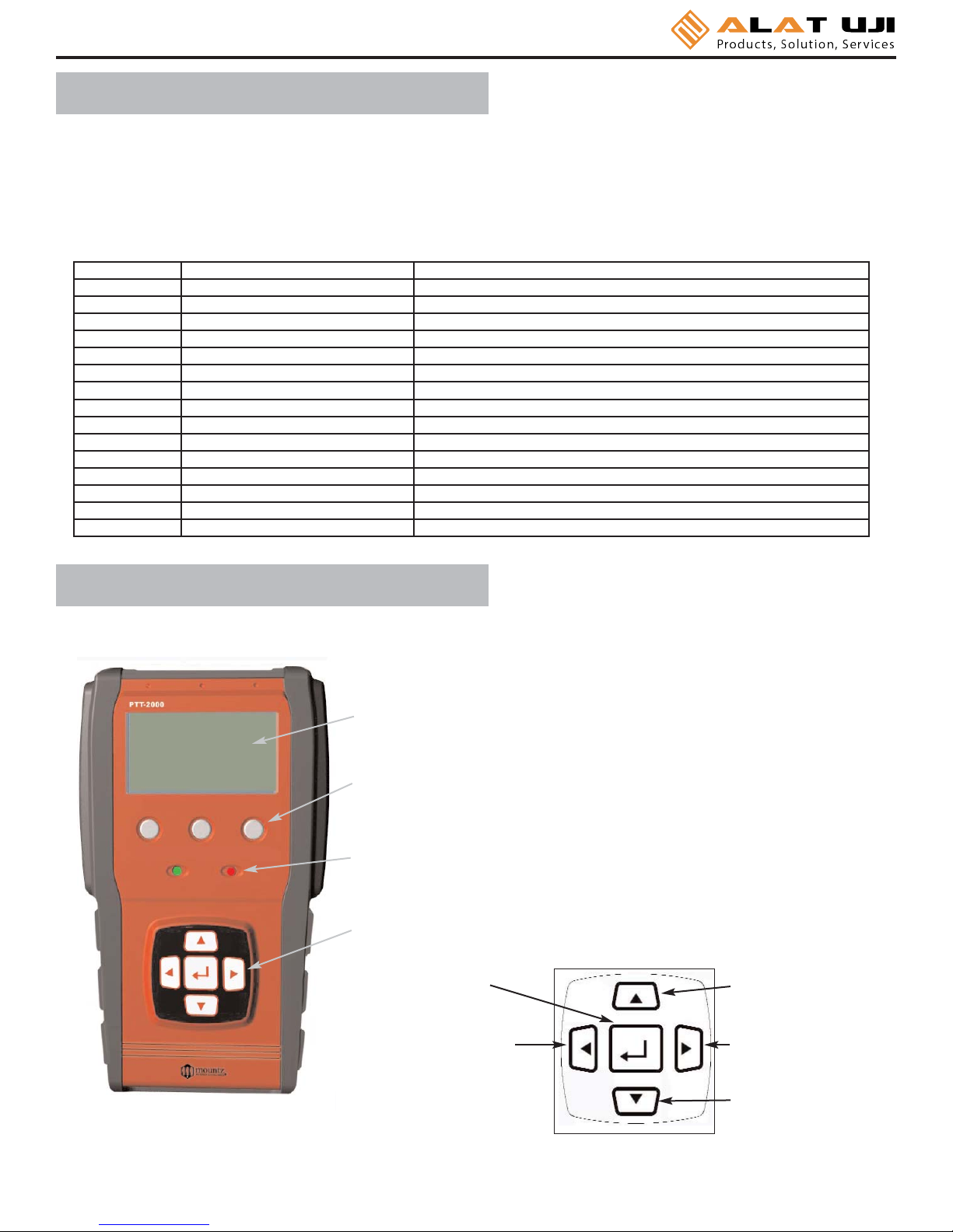
External Connections 2
User Interface 2
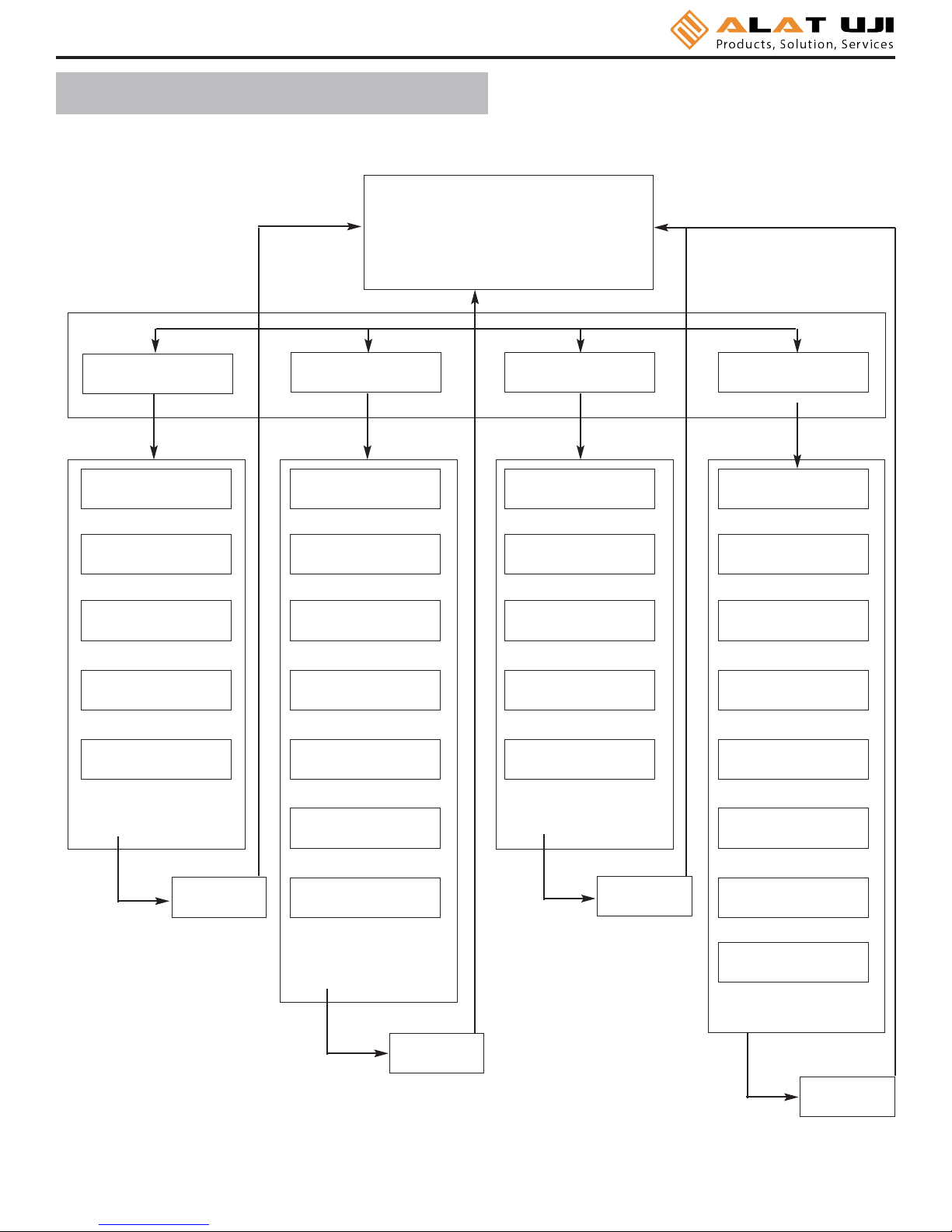
Quick Menu Structure 3
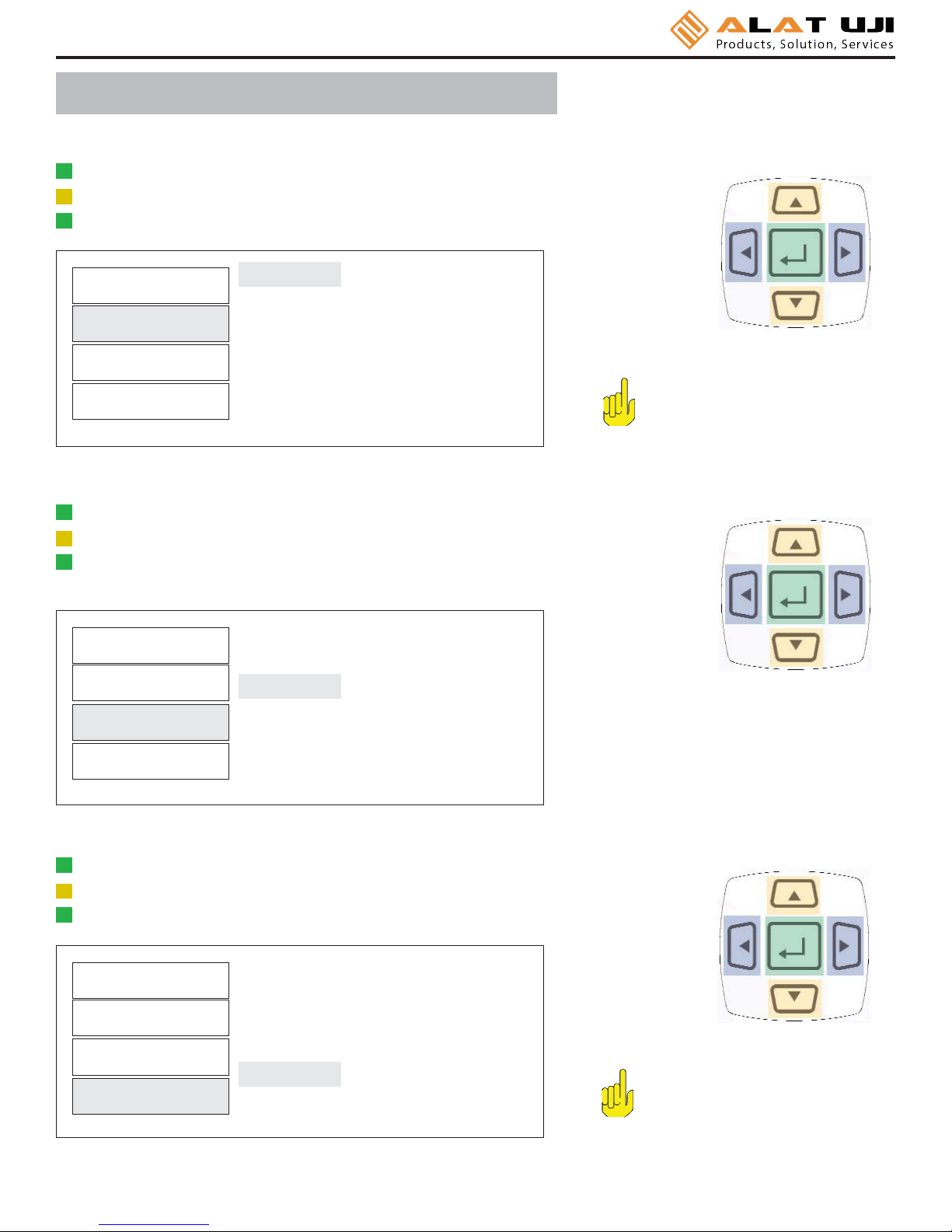
Screen Display 4
Menu Selections 4
Mode Selections 7
Set-Up Selections 8
Power On & Batter Operation 14
Installation of PTT Interface Software 14
Tool Test Operation 17
Transducer Calibration 20
PTT Calibration 21
Data Logging (Graphing) 21
Bootloader 23

User Interface
Page 2
External Connections
USB
The computer connection is USB. There is no setup required. This allows for data to downloaded to a PC. The PC will
require a USB I/O.
External Transducer Input
The transducer connector is a high density D-Sub connector with 15 pins. The pin description is shown below:
Pin Number Function Description
1Analog Ground
2Brushless Signal Output from Brushless Transducer + /- 5V
3Not Used
4Sensor Direct Used to detect transducers
5Digital Ground
6Excitation Voltage + 5V or 16 volts depending on bridge or brush-less transducer
7Bridge Signal - Negative output from bridge transducer
8Not Used
9Angle Lead TTL output from angle detector in angle transducer
10 Sensor Drive Used to detect transducers
11 Bridge Signal + Positive output from bridge transducer
12 Shield
13 Angle Trail TTL output for angle lags Angle Lead by 90 degrees
14 +5 Volt Angle Supply
15 Data for “Smart” Transducer Proprietary ARCII protocol for smart transducers from Mountz
Display Screen
Displays the menu structures, torque readings, operating mode, torque units.
“Scroll and Enter Keys”
Used to toggle through the different menu structures.
Function Keys
For selecting the following options: (Left to Right) Menu, Tool Tests & Cancel
Go and No Go LEDs
Used to monitor lower and upper torque limits and receive a visual warning.
Scroll Up
Scroll Right
Scroll Down
Scroll Left
Enter

Page 3
Quick Menu Structure
Main Display Screen
Peak 1500 Hz
23.783 lbf.in
Menu
Filter Units Mode Setup
Main Menu
3000 Hz
2000 Hz
1500 Hz
500 Hz
200 Hz
ozf.in
lbf.in
lbf.ft
kgf.cm
kgf.m
N.m
cN.m
Track
Peak
First Peak
Audit
Torque & Angle
Tolerance
Auto Clear
Angle Threshold
T+A Threshold
First Peak
Direction
Clock
Sub-Menu
Sub-Menu
Sub-Menu
Sub-Menu
Enter Enter
Enter
Enter
Contrast

Page 4
Screen Display
When the Torque Analyzer is turned on and it is connected to a Mountz "Smart" Torque Transducer with ARCII
technology it will display a Screen similar to that below for 5 seconds and then go into Reading Mode. This will also
happen if a "Smart" transducer is disconnected and another smart transducer is connected.
Mountz PTT-2000
Version 1.00f
Tool Model
BMX750i
Serial Number
04-93-071
If an un-calibrated transducer is connected then the Analyzer will display a screen as below.
Note:
The PTT supports Non-Smart transducers and Non-Mountz transducers. Non-smart transducers can be
detected and can be calibrated in the "internal" memory. The PTT will offer 2 choices. It offers to calibrate or
choose from a list of transducers stored in the internal memory.
Mountz PTT-2000
Version 1.00f
Uncalibrated Transducer -
Connect to Calibration
Software
Note:
When disconnecting a smart transducer and connecting another, the operator must unplug the cable from the
PTT unit.

Page 5
Reading Screen
Track 3000 Hz
+0.0000 Lbf.in
Menu Tool Tests
Menu Selections
Pressing the "Menu" Key will present the following Screen:
1. Use the Scroll Up or Down key to toggle through:Filter, Units, Mode and Setup.
2. Press Enter key to select a choice.
Filter
Units
Mode
Setup
1. Select Filter by highlighting and pressing Enter.
2. Use the Scroll Up or Down key to toggle through the Filter options.
3. Press Enter key to select a Filter Setting.
Filter
Units
Mode
Setup
3000 Hz
2000 Hz
1500 Hz
500 Hz
200 Hz
Selecting Filters
Main
Main Cancel

lbf.in
lbf.ft
ozf.in
kgf.cm
kgf.m
N.m
Menu Selections
1. Select Units by highlighting and pressing Enter.
2. Use the Scroll Up or Down key to toggle through the Unit options.
3. Press Enter key to select a Filter Setting.
Filter
Units
Mode
Setup
Selecting Units
Note:
cN.m is also available but you
must scroll down in the units as it
does not fit on the screen.
Track
Peak
First Peak
Audit
Torque + Angle
1. Select Mode by highlighting and pressing Enter.
2. Use the Scroll Up or Down key to toggle through the Mode options.
3. Press Enter key to select a Mode Setting.
4. The Main (or reading screen) will display the value of the selected Mode.
Filter
Units
Mode
Setup
Selecting Mode Options
Tolerance
Auto Clear
Angle Threshold
T+A Threshold
First Peak
Direction
1. Select Setup by highlighting and pressing Enter.
2. Use the Scroll Up or Down key to toggle through the Setup options.
3. Press Enter key to select a Setup Setting.
Filter
Units
Mode
Setup
Selecting Setup
Note:
Clock is also available but you
must scroll down in as it does not
fit on the screen.
Main Cancel
Main Cancel
Main
Page 6

Mode Selections
This mode constantly tracks increasing or decreasing torque
variations. Use this mode to monitor varying torque on motors
and machinery. Also for calibration and testing of dial torque
products (small wrenches or dial screwdrivers).
Track
Track 1500 Hz
+00.000 lbf.in
Menu Tool Tests
The display retains the highest torque applied. Use this mode
during calibration or testing of any hand type torque wrench
(dial, beam, and screwdriver), as well as power tools.
Peak
Peak 1500 Hz
+ 25.010 lbf.in
Menu Tool Tests
The display holds the first detected torque peak applied. Before any
torque is applied, the display show dashes in the torque value area.
Once peak is detected, the display will show the torque value. If a
second peak is detected then it will be displayed in the lower right (in
small reverse video).
This function is primarily used for testing and calibrating click type
mechanical torque wrenches. The PTT captures the point where the
wrench clicks. This peak may be used for operator training on correct
use of the wrench. Always apply torque smoothly to avoid false first
peak readings.
See page 11 for setting up First Peak.
First Peak
FPK 3000 Hz
------- lbf.in
Menu Tool Tests
FPK 3000 Hz
5.4373 lbf.in
Menu Tool Tests
+7.6261
This mode is used to determine “first movement” or what is commonly
known as “break-away” torque to determine the actual torque on the
joint. An angle enabled transducer is required to operate in this mode.
See page 9 for setting up Angle Threshold.
Audit
Audit 1500 Hz
10.510 lbf.in
Menu Tool Tests
This allows an operator to set up an initial torque and follow up with a
rotation to a specified angle and display the final torque.
The PTT can collect Torque and Angle data if the unit is connected to a
transducer that includes the angle function. It is a "Real Time" angle
function that can capture Torque and Angle up to 8000 RPM.
See page 10 for setting up Torque + Angle.
Torque + Angle
T+A 3000 Hz
9.9985 lbf.in 10 deg
Menu Tool Tests
Page 7
0.00

Tolerance
Auto Clear
Angle Threshold
T+A Threshold
First Peak
Direction
Setup Selections
The Tolerance parameters control the Go and No-Go signal response (see Go / No Go Signal section). The user sets
a lower and upper torque thresholds to get a visual and audible warning signals when these limits are reached or
breached during operation. This function is primarily used for safety and quality control.
Tolerance
Tolerance Setting
Low: _0.000 lbf.in
High: 84.950 lbf.in
Main
1. Press the "Menu" Button.
2. Use the Scroll Down key and select Setup by highlighting and pressing Enter.
3. Use the Scroll Up or Down key to toggle through the Setup options.
4. Press Enter key to select a setup setting for Tolerance.
Filter
Units
Mode
Setup
Selecting Tolerance
1. Press the Right or Left key to toggle between High and Low Tolerance..
2. Use the Scroll Up or Down key to change the tolerance settings .
3. Press Enter key once setting is complete.
4. Press Main button to return to main display screen.
This function controls the method of clearing the display of torque readings.
Auto Clear
When Auto Clear is selected, the torque values, during operation, will automatically be cleared from the display.
The user can set the time threshold to control how long the values should be displayed before clearing.
Manual Clear
When Manual Clear is selected, the torque values during operation will indefinitely be display until the user presses
the Clear key.
Clear
Page 8

Tolerance
Auto Clear
Angle Threshold
T+A Threshold
First Peak
Direction
Auto Clear Setting
Mode: Auto
Time (seconds): 2
Main
1. Press the "Menu" Button.
2. Use the Scroll Down key and select Setup by highlighting and pressing Enter.
3. Use the Scroll Up or Down key to toggle through the Setup options.
4. Press Enter key to select a setup setting for Auto Clear.
Filter
Units
Mode
Setup
Selecting Clear
1. Use the Scroll Up or Down key to toggle between Manual or Auto Clear.
2. Press the Scroll Left or Right key to move down to the Time selection
3. For Auto Clear, use the Scroll Up or Down key to toggle between the selection
of time between 1- 5 seconds.
4. Press Enter key once setting is complete.
5. Press Main button to return to main display screen.
Tolerance
Auto Clear
Angle Threshold
T+A Threshold
First Peak
Direction
This is for the Audit mode. The default setting is 2 degrees, but it can be set from 1 to 5 degrees.
Angle Threshold
1. Press the "Menu" Button.
2. Use the Scroll Down key and select Setup by highlighting and pressing Enter.
3. Use the Scroll Up or Down key to toggle through the Setup options.
4. Press Enter key to select a setup setting for Angle Threshold.
Filter
Units
Mode
Setup
Selecting Angle Threshold
Page 9

Angle Threshold
Angle Threshold: 2 deg
Main
1. Use the Scroll Up or Down key to toggle through the degree values (0.25-5)
It move at increments of 0.25
2. Press Enter key once setting is complete.
3. Press Main button to return to main display screen.
Page 10
Tolerance
Auto Clear
Angle Threshold
T+A Threshold
First Peak
Direction
This allows an operator to set up an initial torque and follow up with a rotation to a specified angle and display the
final torque.
Torque + Angle
Torque+Angle Thresh
Angle: 2.00 deg
Torque: 50.000 lbf.in
Allow Ratchet: No
Main
1. Press the "Menu" Button.
2. Use the Scroll Down key and select Setup by highlighting and pressing Enter.
3. Use the Scroll Up or Down key to toggle through the Setup options.
4. Press Enter key to select a setup setting for Torque + Angle.
Filter
Units
Mode
Setup
Selecting Torque + Angle
1. Press the Right or Left key to toggle between the three settings: Angle, Torque
Allow Ratchet
2. Use the Scroll Up or Down key to set Angle (increments of 0.25)
3. Use the Scroll Up or Down key to set Torque (increments of 0.5)
4. Use the Scroll Up or Down key to set “Yes” or “No” for allowing ratchet*.
5. Press Enter key once setting is complete.
6. Press Main button to return to main display screen.
* Note - “Yes” allows for ratcheting the wrench back without accumulating
angle.

Tolerance
Auto Clear
Angle Threshold
T+A Threshold
First Peak
Direction
The display holds the first detected torque peak applied. Before any torque is applied, the display show dashes in the
torque value area. Once peak is detected, the display will show the torque value. If a
second peak is detected then it will be displayed in the lower right (in small reverse video).
First Peak
First Peak Setup
Sensitivity: Low
Min Peak: 5.0089 Lbf.in
Main
1. Press the "Menu" Button.
2. Use the Scroll Down key and select Setup by highlighting and pressing Enter.
3. Use the Scroll Up or Down key to toggle through the Setup options.
4. Press Enter key to select a setup setting for First Peak.
Filter
Units
Mode
Setup
Selecting First Peak
1. Use the Scroll Up or Down key to toggle through the sensitivity settings:
(Low, Medium & High)
2. Press the Right or Left key to move down to the Min Peak setting location
3. Use the Scroll Up or Down to set the Minimum Peak
4. Press Enter key once setting is complete.
5. Press Main button to return to main display screen.
Page 11
Note:
First Peak Sensitivity
This feature is provided for click wrenches. It is not relevant for Mountz Break-over
or Cam-over products such as MMTB, TB, TBIH, MTBN, TSN, TSP, and TSC.
High sensitivity will clearly display the "double" peak produced by a click wrench.
Low sensitivity will reduce "false peaks" caused by operator hesitation.
For most click wrenches try using Medium sensitivity this works for many types of
click wrenches such as the Mountz Titan and DM wrenches. As different types of
click wrenches differ in how quickly they move from a first peak (click) to a second
peak (over torque). Some experimentation, with sensitivity, may be required in
order to get repeatable results.

Tolerance
Auto Clear
Angle Threshold
T+A Threshold
First Peak
Direction
Allows an operator to set the direction for capturing the torque readings: (Clockwise, Counter Clockwise and Both
directions).
When performing a dead weight calibration, the direction should be set for both directions.
Direction
Direction Setting
Direction: BOTH
Main
1. Press the "Menu" Button .
2. Use the Scroll Down key and select Setup by highlighting and pressing Enter.
3. Use the Scroll Up or Down key to toggle through the Setup options.
4. Press Enter key to select a setup setting for Direction.
Filter
Units
Mode
Setup
Selecting Direction
1. Use the Scroll Up or Down key to toggle through the dIrection settings:
(Both, CW, CCW)
2. Press Enter key once setting is complete.
3. Press Main button to return to main display screen.
Page 12

Page 13
The PTT provides “EZ-Plug & Play” with Mountz Transducers that feature “ARCII” technology, an instant auto-
recognition system of the transducer connected to the PTT. When an ARCII Transducer is connected to the PTT it
automatically recognizes the transducer and displays the Model and Serial Number of the connected transducer on
the PTT.
The information stored in the ARCII chips contains:
The Model of Transducer
The Serial Number of the Transducer
True Calibration Information
Date of Calibration
Auto Clear
Angle Threshold
T+A Threshold
First Peak
Direction
Clock
Clock Setting
2:57 PM
11/15/05
Main
1. Press the "Menu" Button.
2. Use the Scroll Down key and select Setup by highlighting and pressing Enter.
3. Use the Scroll Up or Down key to toggle through the Setup options.
4. Press Enter key to select a setup setting for Clock.
Filter
Units
Mode
Setup
Selecting Clock
1. Use the Scroll Up or Down key to toggle through the digits for the date
and time.*
2. Use the Right and Left key to move through the time and date sections.
3. Press Enter key once setting is complete.
4. Press Main button to return to main display screen.
Note:
Must toggle through the first “time digits” to change from AM to PM.
Six months from the date of the transducer’s calibration a message will appear on the screen informing the
operator it has been six months since the date of calibration. At this point the operator can pull the Transducer out of
service or decide to continue to use it. After the initial message the user will be reminded one a month.
Transducer Calibration Reminder
ARCII (Auto Recognition Chip)

Page 14
The PTT interface software allows the operator to conduct Tool Tests, Sensor Calibration and Meter calibration.
1. Put the disk in and the Installation will start automatically. Click the Next Button to begin installation
2. Enter the required information and click Next Button.
1.
2.
3. Click install.
4. After the installation is successful just click Finish.
3.
4.
Installation of PTT Interface Software
There is no switch to turn the PTT unit. Just press a key and the unit will power on. When the unit has not been used
for a designated time frame it will enter a “Sleep Mode”. The unit features a processor that checks to see if a key
pressed while it is in the Sleep Mode. There is no significant drain on the batteries.
The PTT is powered using the high capacity Li-Ion batteries for a long battery life. The battery pack should last up to
30 hours with normal use and 16 hours with a brushless transducer with a maximum charge. The battery icon is
always on the display. It is filled in completely when fully charged and shows white space as the battery depletes.
Power On & Battery Operation

Page 15
6. Shortly after the PTT is detected the following screen will appear. Do not allow Windows to search for software.
Click "No, not this time".
7. The CD should still be inserted from the installation, but if not insert it. Click "Install from a list or specific location"
and click Next Button.
6. 7.
8. Check the "Search removable media" box and click Next Button.
9. The USB drivers will begin to be installed. If a pop up window appears that the product has not passed the
Windows Logo Testing, just click "Continue Anyway". Mountz has tested the product with both the Home version
and Professional version of XP. You will not get this message if you are installing under Windows 2000.
8. 9.
10.The initial screen will appear The "Online" LED should be green and Torque values are displayed on the right
side of the screen. For most users the only Tab that will be used is the "Tool Tests". The other Tabs are used for
Transducer and Meter calibrations, which should only be done by a certified calibration lab.
5. After installation of the PTT Interface Program turn on the PTT unit. Connect the USB cable to the PTT.
and connect the other end to the computer. The computer detects the device in the lower right side of the screen.

Page 16
10.The initial screen will appear The "Online" LED should be green and Torque values are displayed on the right
side of the screen. For most users the only Tab that will be used is the "Tool Tests". The other Tabs are used for
Transducer and Meter calibrations, which should only be done by a certified calibration lab. Image below is “Torque
Calibration” screen.
11. Image below is “Meter Calibration” screen.

Page 17
12.The Tool Test Screen is below.
The Tool Test mode contains the follow fields.
A. Test Name
B. Sensor Model
C. Tool Serial No.
D. Mode
E. Units
F. Filter
G. Low Tolerance
H. High Tolerance
I. Auto-Clear Mode
J. Auto-Clear Time
K. Direction
L. Comments
M. Operator
N. First Peak Sensitivity
O. Minimum First Peak (% of full scale)
P. Audit Mode (Angle Threshold)
Q. Torque and Angle Mode (Angle Threshold)
R. Torque and Angle Mode (Torque Threshold)
S. Torque and Angle Mode (Allow Angle Ratchet)
Tool Test Operation
All tool tests must be entered using the PC Windows based Calibration Program. Once this is done the tests can be
accessed using the "Tool Test" soft key on the PTT.
Entering data for the Tool Test is done using the PC Windows based Calibration Program. See the Screen above.
Select the “Tool Tests” tab. Enter the relevant information on this screen such as the Test Name, which is the name by
which the test will be identified on the PTT. Then enter all required information on the screen because once the tool test
is activated on the PTT no changes can be made with the units, tolerances or other information. There is a field for
comments to include user specific information. The transducer being used for the Tool Test must be identified. This is
done to prevent a test being run on a transducer with an inappropriate range.
When entering the “Sensor Model” this must match exactly with the sensor identification that was used to identify the
transducer when it was calibrated. If you are not sure about how the transducer is identified, unplug the transducer from
the PTT unit and plug it back in.
Note - the Sensor Model identification appears on the PTT screen during the initialization.
There are various control buttons to perform operations with this program, these include:

Page 18
There are various control buttons to perform operations with this program, these include:
Save - Saves the Tool Test Setups on the PC so it can be used to run further tests in the future.
Open - Opens previously saved Tool Test Setups.
Send - Send a Tool Test to the PTT. It can store up to 100 tests with 25 readings or 25 tests with100 readings or any
similar combination that does not exceed 2500 results
Delete Test in Meter - Deletes this specific test from the PTT. The operator will be asked for confirmation before the
action takes place.
Download Results - Retrieves the results of a tool test after it has been run. It will offer a change to add further notes to
the test at this point. The results will be saved in the PC in C:\PTT 2000\Tool Test Results\Operator Folder where the
"Operator Folder" will be the name of the Operator entered in the upper portion of the Tool Test Screen. The results are
stored in a .csv file which can be opened in Excel or using a text editor program, such a Notepad. The file name will be
the name given to the tool followed by the date and the time at which to test was started.
Clear Data in Meter - Clears the test data for this Tool Test in the PTT meter. Make sure to Download the Results
before clicking this button. The operator will be asked for confirmation before the action takes place.

Page 19
Once 1 or more tool tests are sent to the PTT meter the operator can press the "Tool Test" soft key on the PTT and
following Menu choices will appear:
Select
Start
Stop
Clear Memory
Choose the function desired, from the menu list, by using the Up /Down keys and use Enter key to finalize the selection
highlighted in reverse video.
Select is used to select the desired test from a list of tests that have been downloaded. When an operator selects this
he/she will view an introduction for 3 seconds that provide directions, and then this will display:
Choose Tool Test from List of available tests.
Use Up /Down keys to toggle between tests.
Use Enter to select test.
After the short introduction the operator will see the tool tests displayed and can select the desired test.
Start begins collecting test data. The tool name will be followed by a colon and then the number of data points collected.
Stop ends the test. This is required as some users may want to collect 10 data or others may want to collect 25 points
or more.
Clear Memory allows the test points to be cleared
in the meter itself. The operator will be asked for
confirmation before the action takes place. This
function should only be used if the readings have
been downloaded to the PC or test data is invalid
for some reason.
Once all desired tests are run the operator can
return to the PC to download all Tool Tests stored
in the PTT. During a particular test download the
operator will be given the opportunity to add
further notes to the file stored on the PC.
An example of one Tool Test Result file is shown
on the right.
There is an optional Excel Add-In included on the
PTT CD to perform statistical analysis on the data
from the tool test. It is located in the folder Optional
Excel Statistics Add-In. Follow the instructions in the
readme file, in this folder, to use this Add-In.
Using the Tool Tests on the PTT
Table of contents
Other ALAT UJI Test Equipment manuals