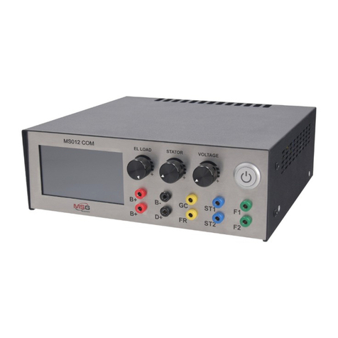
MSG MS012 COM User manual

QUALITY
USER MANUAL
UNIQUENESS
INNOVATION TRAININGSERVICE
MSG MS012 COM
TESTER FOR DIAGNOSTICS
OF VOLTAGE REGULATORS
WARRANTY
2017.05.16

2
User Manual - Tester MSG MS012 COM
1. DESCRIPTION .......................................................................................................................................................3
2. TECHNICAL CHARACTERISTICS........................................................................................................................4
3. CONTROL UNITS..................................................................................................................................................6
3.1 Display...........................................................................................................................................................6
3.2 Buttons and Adjustment Knobs ...........................................................................................................9
3.3 Terminals......................................................................................................................................................10
4. TESTING MODES DISPLAY DATA OUTPUT OF VOLTAGE REGULATORS...................................................10
4.1 Display Data Output when Testing a Voltage Regulator with COM Terminal...........................10
4.2 Display Data Output when Testing a Voltage Regulator with RLO Terminal............................12
4.3 Display Data Output when Testing a Voltage Regulator with SIG Terminal ............................. 12
4.4 Display Data Output when Testing a Voltage Regulator with P-D Terminal ............................13
4.5 Display Data Output when Testing a Voltage Regulator with C Terminal.................................14
4.6 Display Data Output when Testing a Voltage Regulator with D+, 61, L, IL Terminals ............14
5. STEP-BY-STEP INSTRUCTION..........................................................................................................................15
6. TEST CERTIFICATE...............................................................................................................................................16
APPENDIX 1.................................................................................................................................................................17
APPENDIX 2.................................................................................................................................................................19
CONTENTS

3
User Manual - Tester MSG MS012 COM
1. DESCRIPTION
Tester MSG MS012 COM is used for diagnostics of voltage regulators. It simulates installation of
voltage regulator on faultless alternator in order to test its operation under different loads and
modes, under various rotor resistance parameters.
The tester demonstrates how a voltage regulator will operate on the alternator with a certain rotor
resistance. The tester detects if it is possible to install a voltage regulator on the alternator.
A voltage regulator is tested under load, as on the real alternator.
MS012 COM Tester contains the possibility to test all existing types/models of voltage regulators.
New types/models of voltage regulators can easily be added by updating software through USB-
port.
Operation of the tester is conducted by three encoders and a sensor on colored 4.3” TFT display.
MS012 COM Tester is easy and user-friendly in operation. Total testing of a voltage regulator lasts
no longer than 1-2 minutes.

4
2. TECHNICAL CHARACTERISTICS
Fig. 1. MS012 COM Voltage regulator tester - front view
Fig. 2. MS012 COM Voltage regulator tester - back view
User Manual - Tester MSG MS012 COM

5
Supply voltage, V 180-264
90-132
Supply frequency, Hz 50/60
Supply type Single-phase
Maximum consuming power, W 500
Dimensions, mm 260*250*90
Weight, kg 4
Software update Yes
Testing of voltage regulators
Voltage, V 12/24
Resistance of simulated rotor winding, Ohm 1,8-22
Frequency of stator winding (simulation of engine
rotations), rpm 0-6000
Load simulation, % 0-100
Generation voltage adjustment (voltage
regulators with external control) Yes
Tested parameters
- Stabilising voltage
- Current through rotor winding
- COM voltage regulators:
protocol, speed of exchange,
regulator type, errors
- Control lamp
- FR (load on voltage regulator)
Voltage meter accuracy, V 0,1
Ampere meter accuracy, A 0,1
Short circuit protection Yes
Short circuit sound alert Yes
Connection terminals COM, P-D, DFM, D+, RLO, C, SIG
User Manual - Tester MSG MS012 COM

6
MS012 COM Voltage regulator tester is performed in black metallic case with front panel of stainless
steel.
Slot to connect the tester to 220V socket (optional 110V) and safety fuse (2A) are located on the back
panel (Fig. 2).
LCD display, adjustment knobs, power switch and terminals for voltage regulators on the front
panel.
USB B type port used for software update of MS012 COM Tester is located on the left side panel
(Fig. 4).
3. CONTROL UNITS
3.1 C P
Fig. 3. MS012 COM Voltage regulator tester – front panel
Fig. 4. Left side panel - USB port location
User Manual - Tester MSG MS012 COM

7
The tester has short circuit protection. Sound alert turns on in case of short circuit.
In the testing mode parameters of the tester can be set to detect failures in a voltage regulator.
Fig. 5. MS012 COM Voltage regulator tester – Main menu
Button used to activate the testing mode of 12V voltage regulators, which is located
on the sensor display. Menu of terminals for a voltage regulator appears on pressing
the button (Fig. 6).
Button used to activate the testing mode for 24V voltage regulators, which is located
on the sensor display. Pressing the button leads to the testing mode of 24V voltage
regulators.
Button used to enter HELP menu (Fig. 7).
Button of selection of rotor resistance to test a voltage regulator. In order to change
resistance, use the adjustment knob EL LOAD.
Fig. 6. MS012 COM Voltage regulator tester – voltage regulator terminals menu
User Manual - Tester MSG MS012 COM

8
Button to activate voltage regulator testing mode with COM (LIN, BSS) terminal
(Fig. 10).
Button to activate voltage regulator testing mode with RLO terminal (Fig. 12).
Button to activate voltage regulator testing mode with SIG terminal (Fig. 13).
Fig. 7. MS012 COM Voltage regulator tester - Help menu
Button to activate voltage regulator testing mode with P-D terminals (Fig. 14).
Button to activate voltage regulator testing mode with C terminal C (Fig. 15).
Button to activate voltage regulator testing mode with D+, L, IL, 61 terminals (Fig. 16).
Button to return to the previous menu (Fig. 5).
Button to return to the main menu (Fig. 5).
• Tech support: manufacturer contact details menu.
• Service data: service data of the tester.
• Search relay: button is inactive (prospective development).
• EXIT: return to the main men (Fig. 5).
User Manual - Tester MSG MS012 COM

9
3.2 B A K
Fig. 8. MS012 COM Voltage regulator tester – adjustment knobs and on/off switch
MS012 СОМ Voltage regulator tester on/off switch.
• EL LOAD: the adjustment knob with two functions: required resistance of simulated rotor can
be set in the main menu, in voltage regulator testing mode (12V/24V), the load on the simulated
alternator and on a tested voltage regulator, respectively, can be changed from 0% to 100%.
• STATOR: the adjustment knob to change frequency of stator winding from 0 to 6000 in voltage
regulator testing mode (12V/24V). The frequency appear on the display as car engine rotation
frequency.
• VOLTAGE: the adjustment knob to set required current voltage generated by a voltage
regulator in voltage regulator testing mode (12V/24V). Used with terminal modes: COM (LIN,
BSS); RLO; C; SIG; P-D.
User Manual - Tester MSG MS012 COM

10
• В+: voltage regulator plus (30 or 15 terminal).
• В-: voltage regulator minus (earth).
• D+: voltage regulator control lamp terminal, used to connect voltage regulator outputs:
D+; L; IL; 61.
• ST1; ST2: terminals for stator windings of the simulated alternator to connect voltage regulators
stator outputs.
• GC: terminal to connect voltage regulator terminals: COM (LIN, BSS); SIG; RLO; P-D; C.
• F1; F2: terminals for rotor of the simulated alternator, used to connect voltage regulator brushes
or the corresponding voltage regulator outputs.
4.1 D D O W T V
R W COM T
4. TESTING MODES DISPLAY DATA OUTPUT
OF VOLTAGE REGULATORS
Fig. 10. Graphical symbol of COM terminal location in most
common terminals of voltage regulators
3.3 T
Fig. 9. Voltage regulator tester MS012 COM – terminals
User Manual - Tester MSG MS012 COM

11
Fig. 11. Display data output when testing a
voltage regulator with terminal COM
• BOD: speed of voltage regulator data transfer. LIN protocol voltage regulators operate with
speeds: 19200 (High), 9600 (Average), 2400 (Low). BSS protocol voltage regulators operate with
speed: 2400 (Low).
• ERROR: voltage regulator operation errors. The following symbols are used: EL – electric error
(voltage does not correspond to the required voltage indicators of a voltage regulator; probably,
internal operating transistor is out of service); ME – mechanic error (stator winding is not
connected); TM – thermal error (overheat of voltage regulator exceeds 150°C).
• LOAD: load on a voltage regulator. It indicates simulated load on a voltage regulator. Load is set
manually with the adjustment knob EL LOAD. On increasing the load, the current in brushes of a
voltage regulator increases as well.
• STATOR: simulated frequency of engine rotation where the alternator with a tested voltage
regulator is installed. Frequency is set manually with the adjustment knob STATOR from 0 to
6000 rpm.
• COM: set voltage on a voltage regulator. It is set manually with the adjustment knob VOLTAGE
with possible values from 10,6 V to 16 V.
• DFM: load control on the alternator with indicators from 0% to 100%. All data is read in digital
format in accordance with the corresponding protocol.
• VOLTAGE: stabilizing voltage of a voltage regulator.
• CURRENT: current in voltage regulator brushes.
• BACK: return to the previous menu (Fig. 6).
• EXIT: return to the main menu (Fig. 5).
• PROTOCOL: protocol of a voltage regulator.
Protocol titles, appearing on the display: BSS,
LIN 1.3, LIN 2.0.
• TYPE: type of a voltage regulator, it can be A
and B type. Voltage regulators of BSS protocol
operation can only be A type.
• ID: voltage regulator identification number.
Possible values: from 1 to 254. Electronic
control module of a car detects the presence
of the alternator by this identification
User Manual - Tester MSG MS012 COM
number. In case of inconsistency, faultless alternator launches emergency mode or does not
start at all. In this case a message of failure appears on the display.

12
4.2 D D O W T V
R W RLO T
Fig. 12. Display data output when testing a
voltage regulator with terminal RLO
voltage regulator is installed. Frequency is set manually with the adjustment knob STATOR from
0 to 6000 rpm.
• RLO: set voltage on a voltage regulator. It is set manually with the adjustment knob VOLTAGE.
• DFM: load control on the alternator with indicators from 0% to 100%. All data is read from FR
output of a voltage regulator.
• BACK: return to the previous menu (Fig. 6).
• EXIT: return to the main menu (Fig. 5).
4.3 D D O W T
V R W SIG T
• V: stabilizing voltage of a voltage regulator.
• A: current in voltage regulator brushes.
• : control lamp (control lamp simulation
on car control panel).
• LOAD:loadonavoltageregulator.Itindicates
simulated load on a voltage regulator.
Load is set manually with the adjustment
knob EL LOAD.
• STATOR: simulated frequency of engine
rotation where the alternator with a tested
• V: stabilizing voltage of a voltage regulator.
• A: current in voltage regulator brushes.
• LOAD: load on a voltage regulator. Indicates simulated load on a voltage regulator. Load is set
manually with the adjustment knob EL LOAD.
• STATOR: simulated frequency of engine rotation where the alternator with a tested voltage
regulator is installed. Frequency is set manually with the adjustment knob STATOR from 0 to
6000 rpm.
User Manual - Tester MSG MS012 COM

13
Fig. 13. Display data output when testing a
voltage regulator with SIG terminal
• SIG: set voltage on a voltage regulator
through terminal SIG. It is set manually with
the adjustment knob VOLTAGE.
• DFM: load control on the alternator. Possible
values: from 0% to 100%. All data is read
from FR output of a voltage regulator.
• BACK: return to the previous menu
(Fig. 6).
• EXIT: return to the main menu (Fig. 5).
4.4 D D O W T V
R W P-D T
Fig. 14 Display data output when testing a
voltage regulator with P-D terminal
• V: stabilizing voltage of a voltage regulator.
• A: current in voltage regulator brushes.
• LOAD:loadonavoltageregulator.Itindicates
simulated load on a voltage regulator. Load
is set manually with the adjustment knob
EL LOAD.
• STATOR: simulated frequency of engine
rotation where the alternator with a tested
voltage regulator is installed. Frequency is
set manually with the adjustment knob
STATOR from 0 to 6000 rpm.
• D: set voltage on a voltage regulator. It is set manually with the adjustment knob VOLTAGE.
• P: engine rotation frequency indicator. Through this terminal the control module detects rotor
rotation and if the belt is safe. Only in this case the command signal to output D is sent.
• BACK: return to the previous menu (Fig. 6).
• EXIT: return to the main menu (Fig. 5).
User Manual - Tester MSG MS012 COM

14
4.5 D
C
Fig. 15. Display data output when testing a
voltage regulator with terminal С
voltage regulator is installed. Frequency is set manually with the adjustment knob STATOR from
0 to 6000 rpm.
• C: set voltage on a voltage regulator. It is set manually with the adjustment knob VOLTAGE.
• DFM: control indicator of load on the alternator. Possible values: from 0% to 100%. All data is
read from FR output of a voltage regulator.
• BACK: return to the previous menu (Fig. 6).
• EXIT: return to the main menu (Fig. 5).
• V: stabilizing voltage of a voltage regulator.
• A: current in voltage regulator brushes.
• : control lamp (control lamp simulation
on car control panel).
• LOAD:loadonavoltageregulator.Itindicates
simulated load on a voltage regulator.
Load is set manually with the adjustment
knob EL LOAD.
• STATOR: simulated frequency of engine
rotation where the alternator with a tested
4.6 D D O W T V
R W D+, L, IL, 61 T
Fig. 16. Display data output when testing a
voltage regulator with D+,L, IL, 61 terminals
• VOLTAGE: stabilizing voltage of a voltage
regulator.
• CURRENT: current in voltage regulator
brushes.
• LOAD:loadonavoltageregulator.Itindicates
simulated load on a voltage regulator. Load
is set manually with the adjustment knob
EL LOAD.
• : control lamp (control lamp simulation
on car control panel).
User Manual - Tester MSG MS012 COM

15
• STATOR: simulated frequency of engine rotation where the alternator with a tested voltage
regulator is installed. Frequency is set manually with the adjustment knob STATOR from 0 to
6000 rpm.
• DFM: control indicator of load on the alternator. Possible values: from 0% to 100%. All data is
read from FR output of a voltage regulator.
• BACK: return to the previous menu (Fig. 6).
• EXIT: return to the main menu (Fig. 5).
5. STEPBYSTEP INSTRUCTION
Voltage regulator testing starts from identifying which operating terminal and voltage regulator
outputs are used, which outputs of the tester must be connected to a voltage regulator.
Therearevoltageregulatorswithstatorconnection(ST1and ST2 outputs ofthetester),orconnection
through additional diodes, known as “Trio” (B+ output of the tester).
Learn the connection to the real alternator for correct connection of a voltage regulator to the
tester. If it is impossible, use APPENDIX 1 of actual User Manual.
When the correct way of connection to the tester is identified, it is recommended to measure
alternator rotor resistance with an ohmmeter, where a voltage regulator was previously installed
for more accurate testing.
Set resistance of simulated rotor winding, using the adjustment knob EL LOAD. Indicators appear on
the display of the main menu (Fig. 5).
After resistance is set, enter the testing mode for 12V or 24V voltage regulators of by pressing the
relevant button (Fig. 5). Select the corresponding control terminal for a voltage regulator (Fig. 6).
Connect a voltage regulator in following sequence: B+/B-/voltage regulator control terminal (COM,
RLO, SIG, P-D, C, D+)/F1 and F2/ST1 and/or ST2, or B(in case when a voltage regulator is connected
to additional diodes).
Voltage and current indicators of a voltage regulator appear on the display.
Voltage regulator operability can be determined by stabilizing voltage indicators and by changes in
current consumption under different loads.
COM terminal voltage regulators are considered to be faultless if stabilizing voltage corresponds to
the set voltage and when no error messages appear on the display.
Voltage regulators with P-D, SIG, RLO, C terminals are considered to be faultless if stabilizing voltage
changes according to the set voltage.
User Manual - Tester MSG MS012 COM

16
Non-adjustable voltage regulators (D+, Land others) are considered to be faultless if stabilizing
voltage ranges from 13.8 to 14.8 V for 12 V voltage regulators, from 27.6 to 29.6 V for 24 V voltage
regulators and current changes in direct proportion to the set load.
User Manual - Tester MSG MS012 COM
6. TEST CERTIFICATE
Tester MSG MS012 СОМ for voltage regulators meets technical requirements of Directive
2014/30/EU - Electromagnetic Compatibility (EMC) EN Directive 2014/35/EU - Low voltage
(LVD) Directive 2006/42/EC - Machinery (MD) and is qualified for exploitation.

17
Indicial notation Functional purpose Terminal
B+ Battery (+)
B+
30
A
(Ignition) Input for switch startingIG
15
AS Alternator Sense
BVS Battery Voltage Sense
S(Sense) Input for voltage
comparison at control point
B- Battery (-) B-
31
E Earth, battery (-)
D+ Used for connection to an indicator lamp that transfers initial driving
voltage, and indicates alternator operability
L/D+
I Indicator
IL Illumination
L(Lamp) Output for alternator operability indicator lamp
61
FR (Field Report) Output for load control on an alternator by engine
management block
FR
DFM Digital Field Monitor
M Monitor
LI (Load Indicator) Same as FR, but with universal signal
(Drive) Input of voltage regulator control with P-D terminals Mitsubishi
D(Drive) Input of voltage regulator control with terminal P-D Mitsubishi
(Mazda) and Hitachi (Kia Sephia 1997-2000) GC
D(Digital) Input of code voltage installation
on American Ford, same as SIG GC
RC (Regulator Control) same as SIG
SIG (Signal) Input of code voltage installation
Connection of Terminals to Alternators
APPENDIX 1
User Manual - Tester MSG MS012 COM

18
RVC(L) (Regulated Voltage Control) Similar to SIG, but voltage change ranges
from 11.0 V to 15.5 V. Control signal is sent to L terminal
C(Communication) Voltage regulator input to control engine operation
block. Japanese cars
GC
G
RLO (Regulated Load Output) Input to control stabilizing voltage
from 11,8 to 15 V (TOYOTA)
COM
(Communication) General term for physical interface, alternator control and
diagnostics. Protocols of use: BSD (Bit Serial Device), BSS (Bit Syn-
chronized Signal) or LIN (Local Interconnect Network)
LIN Direct indication on control interface and alternator diagnostics, con-
ducted under LIN protocol (Local Interconnect Network)
DF
Output of voltage regulator F1; F2
F
FLD
67
P
Output of one of alternator stator windings. Used for measuring
alternator driving voltage
S
STA
Stator
W(Wave) Output of one of alternator stator windings for connection of
tachometers in diesel engine cars
N
(Null) Output of average stator winding point. Usually used to regulate
alternator operability with mechanically regulated voltage
by an indicator lamp
D (Dummy) Blank, no connection, mostly in Japanese cars
N/C (No connect) No connection
Options of LRC
voltage regulators
(Load Response Control) Function of voltage regulator response delay on
load increase on an alternator. Delay duration ranges from 2,5 to 15 seconds.
On increasing the load (lights, cooler fan on), a voltage regulator
adds driving voltage smoothly ensuring stability of engine drive
rotation. Remarkably seen under idle running
User Manual - Tester MSG MS012 COM

19
Connection of Voltage Regulators to MS012 COM
Voltage Regulator Tester
APPENDIX 2
User Manual - Tester MSG MS012 COM

20
User Manual - Tester MSG MS012 COM
Other manuals for MS012 COM
2
Table of contents
Other MSG Test Equipment manuals