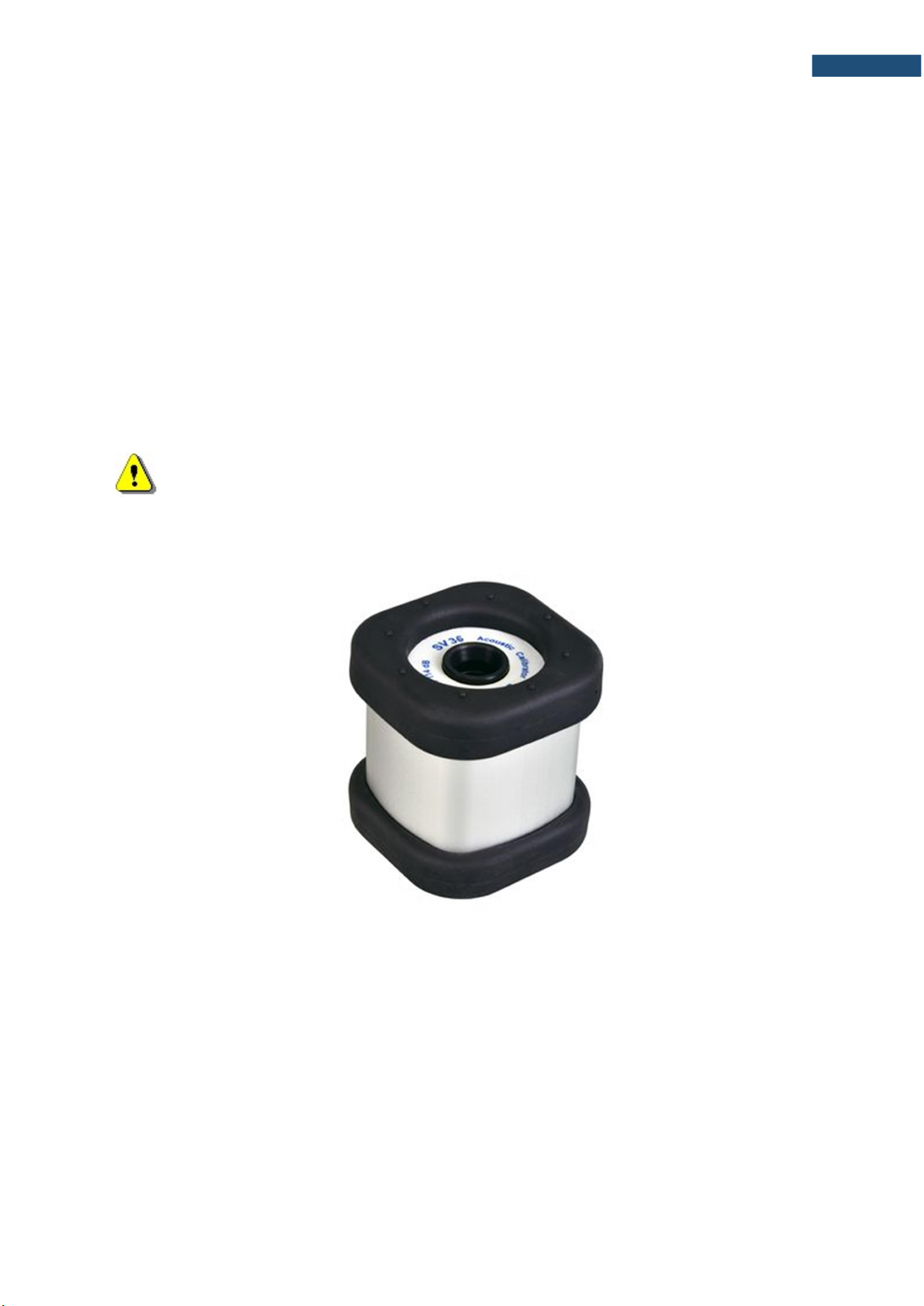
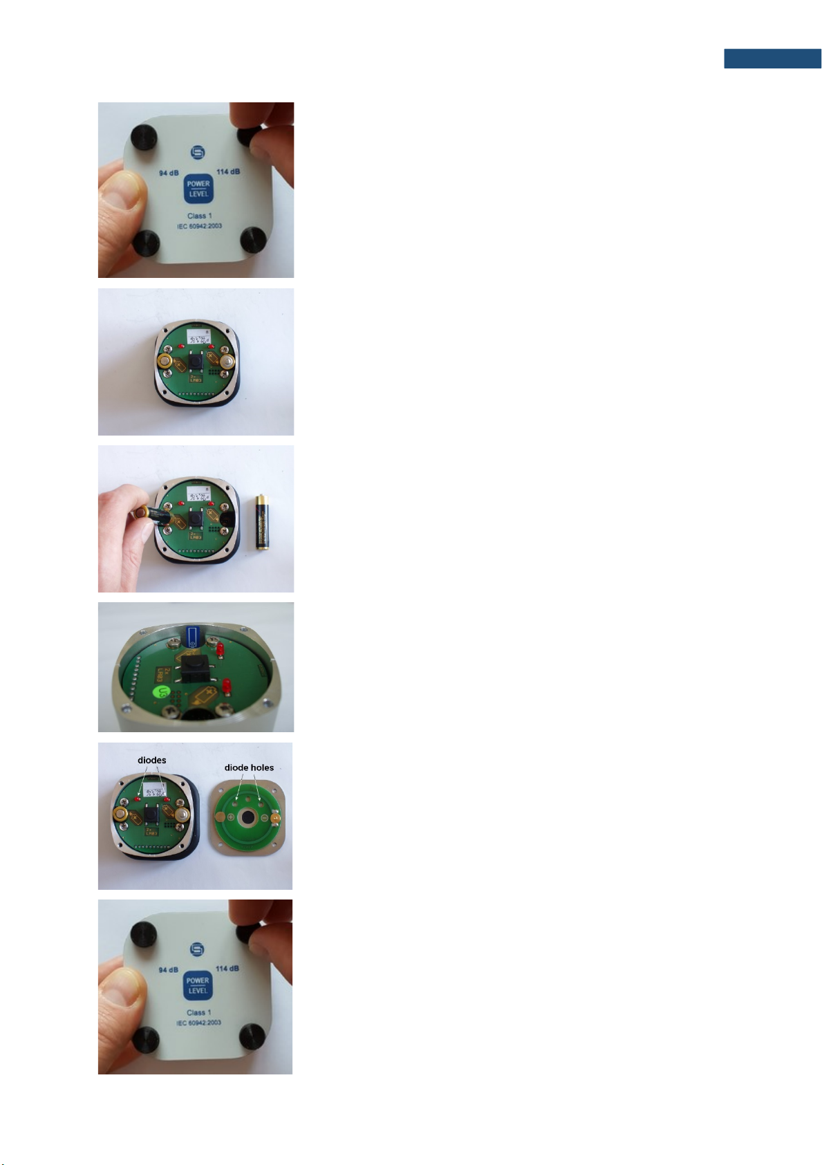
2.2.2. Button functions
The SV 36 calibrator is equipped with a multifunctional button for controlling operation of the
device. The functions of the button depend on the state of the calibrator (ON/OFF) and on
the time of its pressing (see Table 2).
When the calibrator is OFF, pressing the button turns it on immediately. Range
is automatically set to that one in which the calibrator was switched off. If the calibrator is not
put on the microphone within 3-5 seconds from turning on, it will switch off automatically.
When the calibrator is ON, short pressing of the button (less than 3-5 sec.) will cause
switching the range from 94 dB to 114 dB or the other way round.
Either when the SV 36 is ON or OFF pressing the button over 10 seconds and releasing it
will cause full reset of the system. Normally this function is not necessary. It has been
implemented in the case of inappropriate operation of the calibrator caused by external (EM
radiation, subnormal atmospheric conditions, etc.) or internal (inappropriate system reset as
a result of battery replacement) factors.
The operation time of the calibrator with a microphone put inside its chamber
is limited to 3 minutes. This functionality was added in order to save the battery, e.g. when
the calibrator is accidentally left with the microphone inside.
Note:
Leaving the SA 30 reduction adapter in the chamber of the calibrator is
equivalent with the state of the microphone being left inside. Hence, the
calibrator will switch off automatically after 3 minutes from the moment the
adapter is put inside the calibrator.
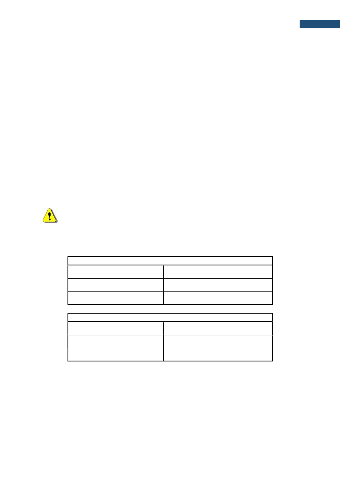
Table 2. Functional description of the calibrator’s button.
Button press Function description
Short, less than 3 sec. Turn on the device
Over 10 sec. Full reset of the system
Button press Function description
Short, less than 3 sec. Change the range of the device
Over 10 sec. Full reset of the system
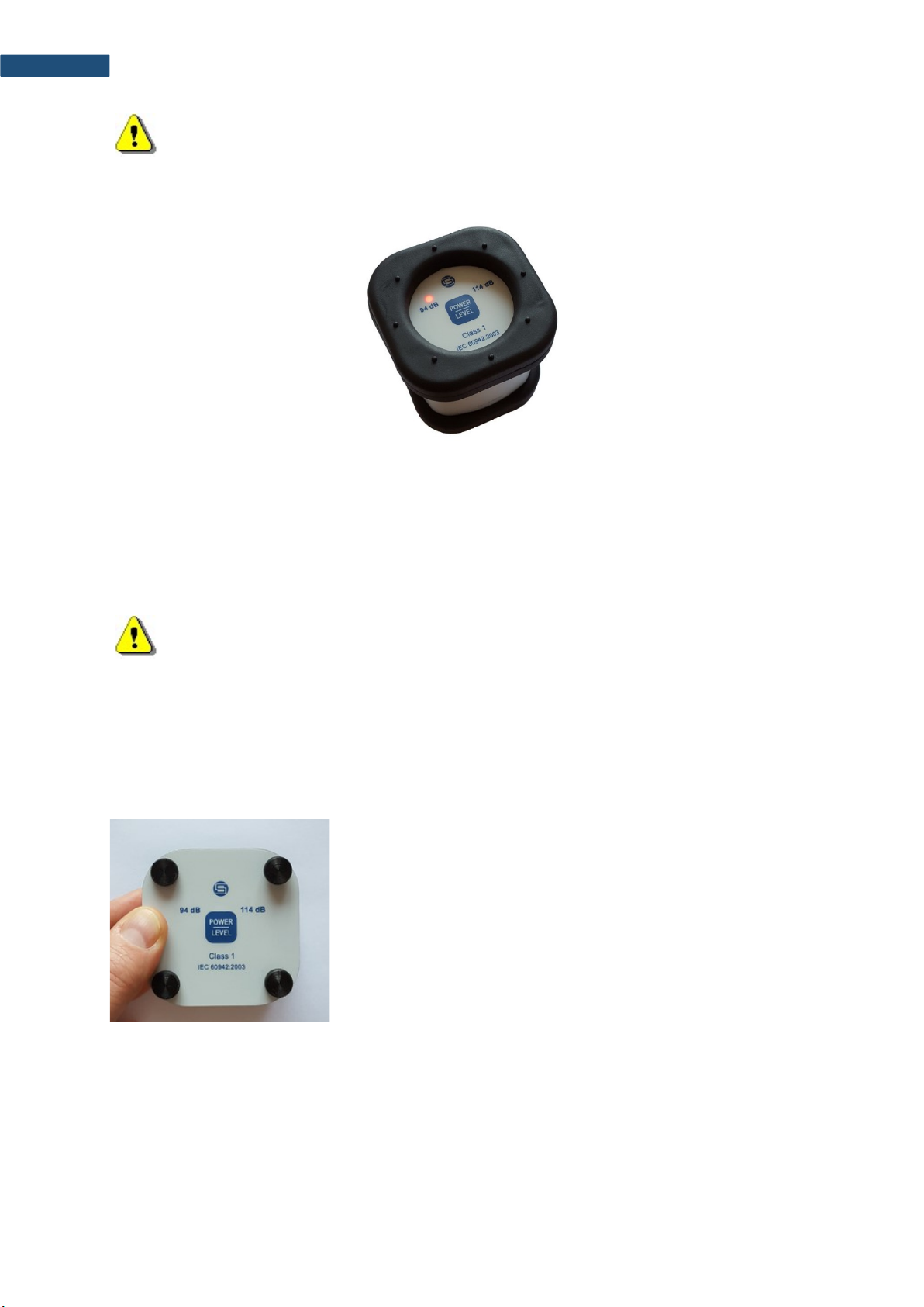
2.2.3. Range diodes
In normal mode of operation, the calibrator’s diodes act as range indicators. In this mode
diode of the chosen range is lighting with continuous light, indicating that the device is ready
for to start the calibration procedure (see Picture 4).
After the calibrator is put on the microphone, switched on or the range is changed, acoustic
pressure inside the calibrator’s chamber is adjusted to the desired level. During that process,
appropriate range diode blinks with a frequency of 2 Hz.