SilverNet MICRO TG60 User manual

V1.0 www.silvernet.com
SIL MICRO TG60 QUICK SETUP GUIDE
This guide will cover all the necessary steps to quickly configure, install and troubleshoot the
SilverNet MICRO TG60. It will be split into 3 sections: Installation, Configuration and
Common Problems.
FIRST GLANCE
Before beginning to install a link, you must ensure all the necessary equipment is in the box.
Please see below for package contents:
The box should contain the following: 1x Radio, 1x PoE Injector, 1x IEC C5 Power Cable, 1x
Steel-Band Clamps for Pole Mounting (3” Diameter Max), 2x Screws with Nylon Expansion
Plugs for Wall Mounting, 2x Cable Glands, 1x Quick Start Guide.

SIL MICRO TG60 Quick Setup Guide 2
OVERVIEW
#
Name
Description
1
Integrated Pole and
Wall Mounting Plate
Mounting plate containing 4x screw holes and 2x strap holes for
versatile mounting.
2
System LED Indicators
LAN: On (LAN Port Connection), Blinking: (Activity).
Uplink(PoE): On (Uplink PoE Port Active), Blinking (Activity). Slow Blink
during system boot up.
60G: On (60GHz Wireless Link Established), Blinking (Activity).
3
Grounding Screw
For ground wire connection.
4
LAN Port
Provides LAN Connectivity only.
5
Uplink PoE Port
Receives PoE Input from PoE Device and LAN Connectivity.
5
4
1
2
3

SIL MICRO TG60 Quick Setup Guide 3
INSTALLATION
Warning: For a safe and reliable installation, only use the provided accessories and screws.
Use of other accessories and screws could result in damage to the unit. Any damages
incurred by using unapproved accessories are not covered under warranty.
STEP 1: GROUND THE MICRO TG60
Ground the SIL TD60G by connecting a ground wire to the grounding point as shown above
to a nearby earth ground.

SIL MICRO TG60 Quick Setup Guide 4
STEP 2: ESTABLISH CONNECTIONS
Connect your outdoor-rated Cat5e or higher cable to the 1000BaseT RJ45 Uplink PoE port.
This port is capable of receiving PoE Input and LAN Traffic. Be sure to also install the included
weatherproof cable gland as shown above.
Optional: Using the LAN port, connect to a local LAN host. Be sure to also install the included
cable gland on this port as well.

SIL MICRO TG60 Quick Setup Guide 5
STEP 3: MOUNTING THE MICRO TG60 (POLE MOUNT)
Firstly, feed the steel-band clamp through the pole mount bracket points on the back of the
MICRO TG60 as shown above and lightly fasten them around the pole.
Next, align your MICRO TG60 with its partner radio. Once a good signal has been established,
tighten the clamps securely.
SIL MICRO TG60 Quick Setup Guide 6
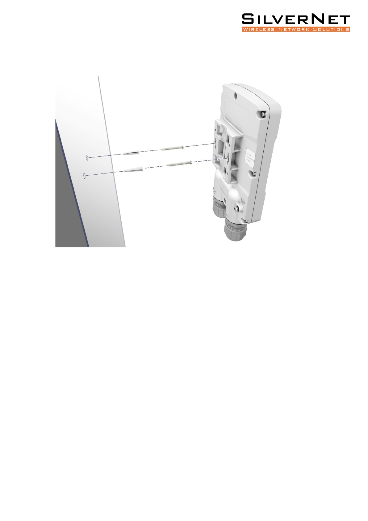
MOUNTING THE MICRO TG60 (WALL MOUNT)
Begin by drilling two holes in the wall for the included expansion plugs. Insert the expansion
and both screws into the holes.
Align the MICRO TG60 mounting plate with the screws and then slide the radio down until it
snaps into its secured position.

SIL MICRO TG60 Quick Setup Guide 7
PRECISION BRACKET MOUNTING (OPTIONAL)
Two optional extra precision brackets (ordered separately) are designed for wall and pole
mounting and provide additional degrees of movement for antenna alignment.
SIL MICRO TG60 Quick Setup Guide 8
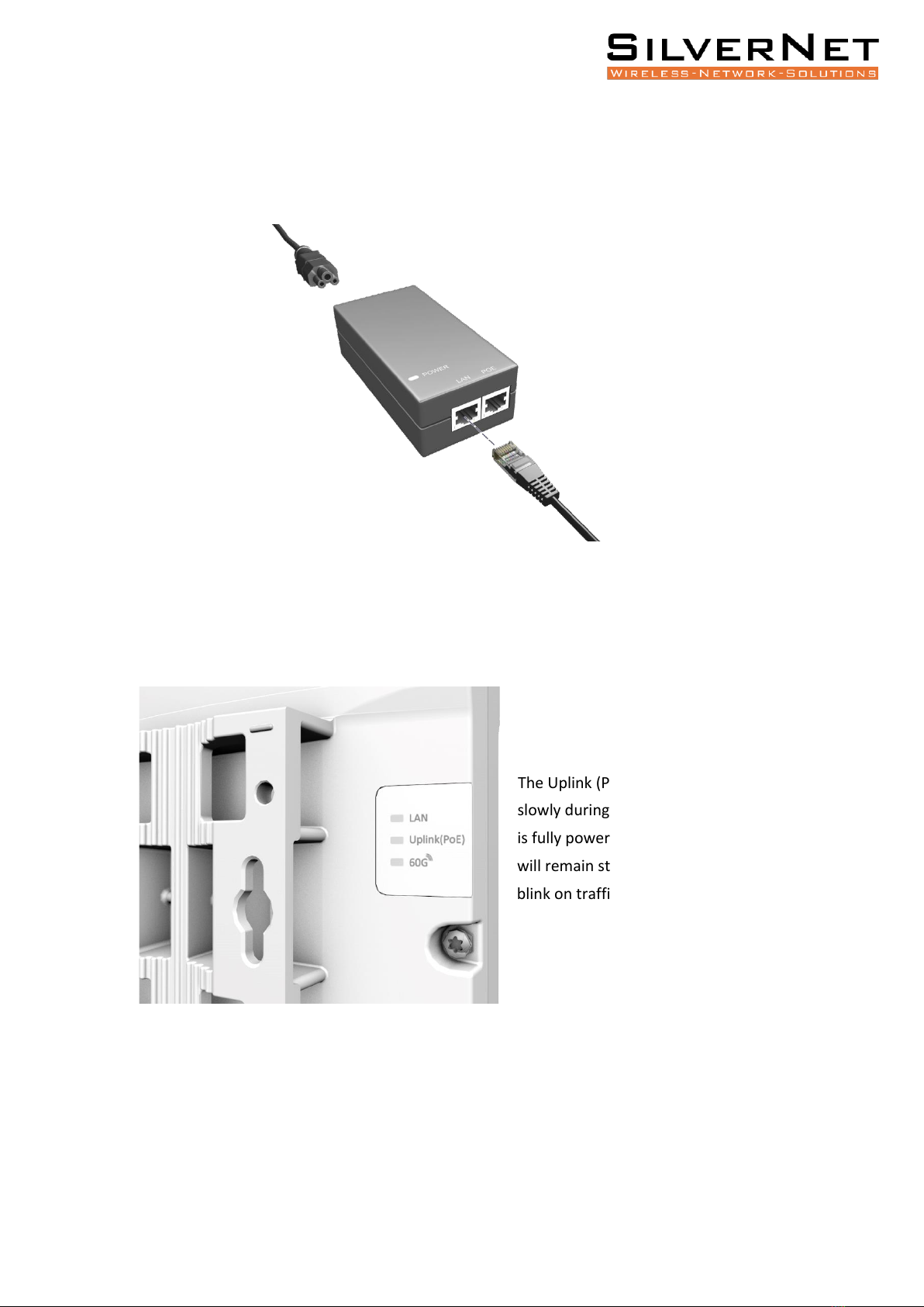
POWER
To begin, power up your device. Connect the other end of your Ethernet cable from the
Uplink PoE port to the PoE Injector (passive) which was provided in the box.
After you have connected your radio to the PoE Injector, verify that the power is On by
checking the LEDs on the back of the radio.
The Uplink (PoE) LED should blink
slowly during boot-up. Once the radio
is fully powered and idling, the LED
will remain static or intermittently
blink on traffic.

SIL MICRO TG60 Quick Setup Guide 9
CONFIGURATION
To first connect to your device, ensure you configure your network adapter to be within the
same subnet as the radio. For example, if using the radio’s LAN port, the radio is on IP
address 192.168.2.1 with a subnet mask of 255.255.255.0, you will need to configure your
adapter with an address of 192.168.2.X (where X can be 2-254) and a subnet mask of
255.255.255.0. If you are using the PoE Injector for connectivity, the radio will be on IP
address 192.168.1.20 with a subnet mask of 255.255.255.0, therefore you will need to
configure your adapter with an address of 192.168.1.X and a subnet mask of 255.255.255.0.
(Please note if using the PoE Port, the radio is configured as a DHCP client and will receive an
address from a DHCP server where applicable).
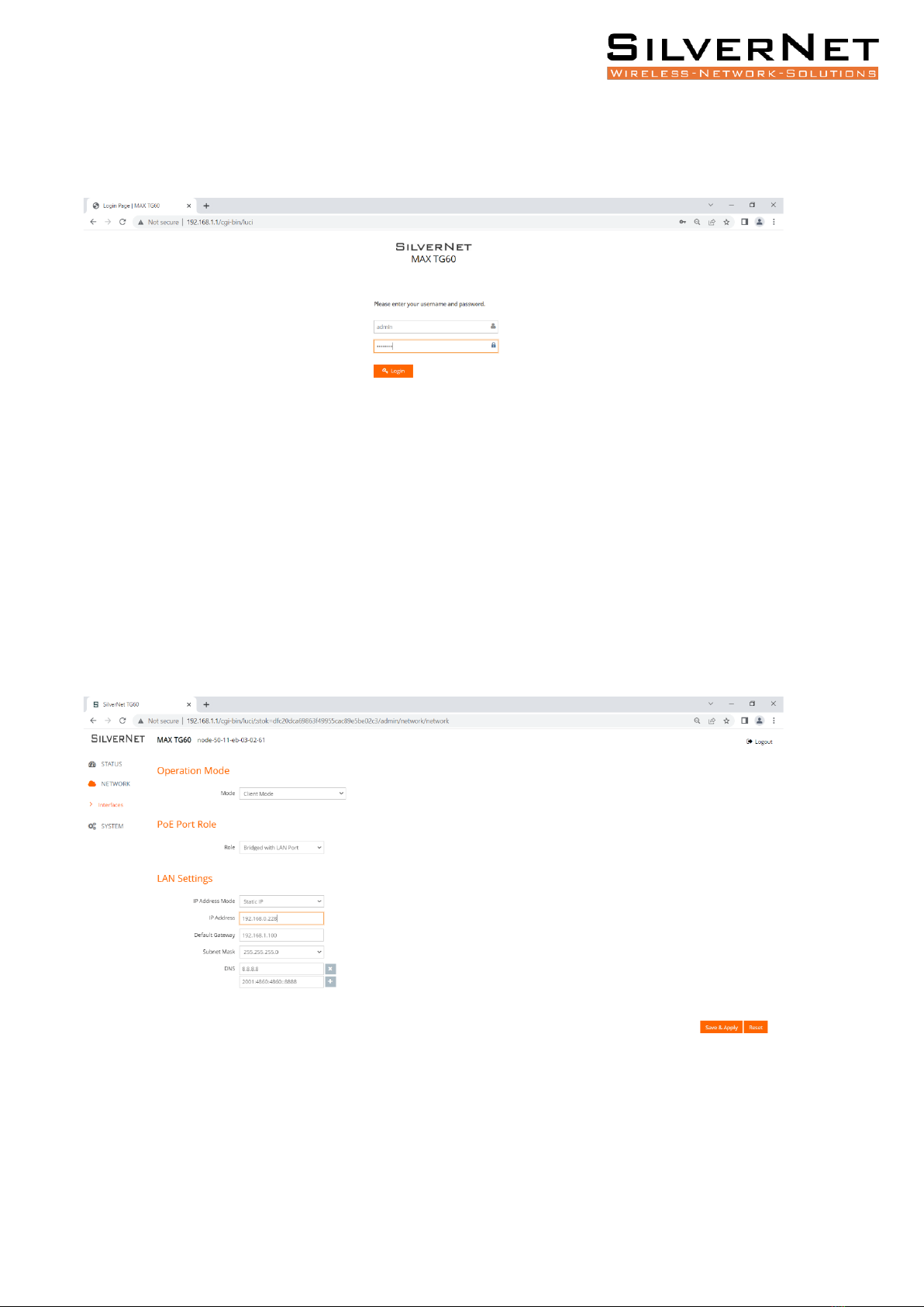
Once you have got this configured, enter the specified port IP address into your Web
Browser of choice URL bar. The default login details are as follows:
•Username: admin
•Password: password
Once logged in, you will need to configure your link. Please note that you only need to
configure the Link settings in one end of the link. The partner radio will automatically
connect.
SIL MICRO TG60 Quick Setup Guide
10
Step 1: If your radio has not been configured, login to your radio on 192.168.1.1 with the
above details.
Step 2: Navigate to “Network > Interfaces”. If configuring the client radio, simply leave the
radio on “Client Mode” and input your designated IP address then click “Save and Apply”.
Once this has been set, your client radio is fully configured.
SIL MICRO TG60 Quick Setup Guide
11
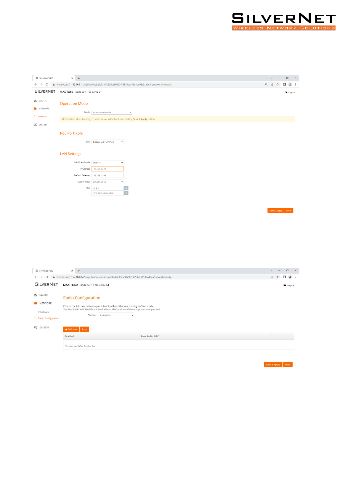
Step 2a: If you are configuring your AP radio, change the “Operation Mode” to “Base Station
Mode” and input your designated IP address & click “Save and Apply”.
Step 3 (only applicable to AP radio): Navigate to “Network > Radio Configuration”.

SIL MICRO TG60 Quick Setup Guide
12
Step 4: Press the “Scan” button to start a partnering scan. Alternatively, you can manually
input the details of your partner radio by clicking “Add New” then inputting the Radio MAC
address of the partner radio. This can be found under the “Status Page”.
Step 4a: Once your partner radio appears within this scan window, simply select it by
highlighting the tick box and click “Add Selected as Links”. Once this has been done, your
partner radio should appear as below. Click “Save and Apply”.

SIL MICRO TG60 Quick Setup Guide
13
Step 5: To verify a full connection, navigate to “Status > Link Status”. This will display your
current partner radio as well as some useful RF statistics such as Channel, RSSI, Tx Power etc.
SIL MICRO TG60 Quick Setup Guide
14
COMMON PROBLEMS
Below is a list of some common problems and how to resolve them;
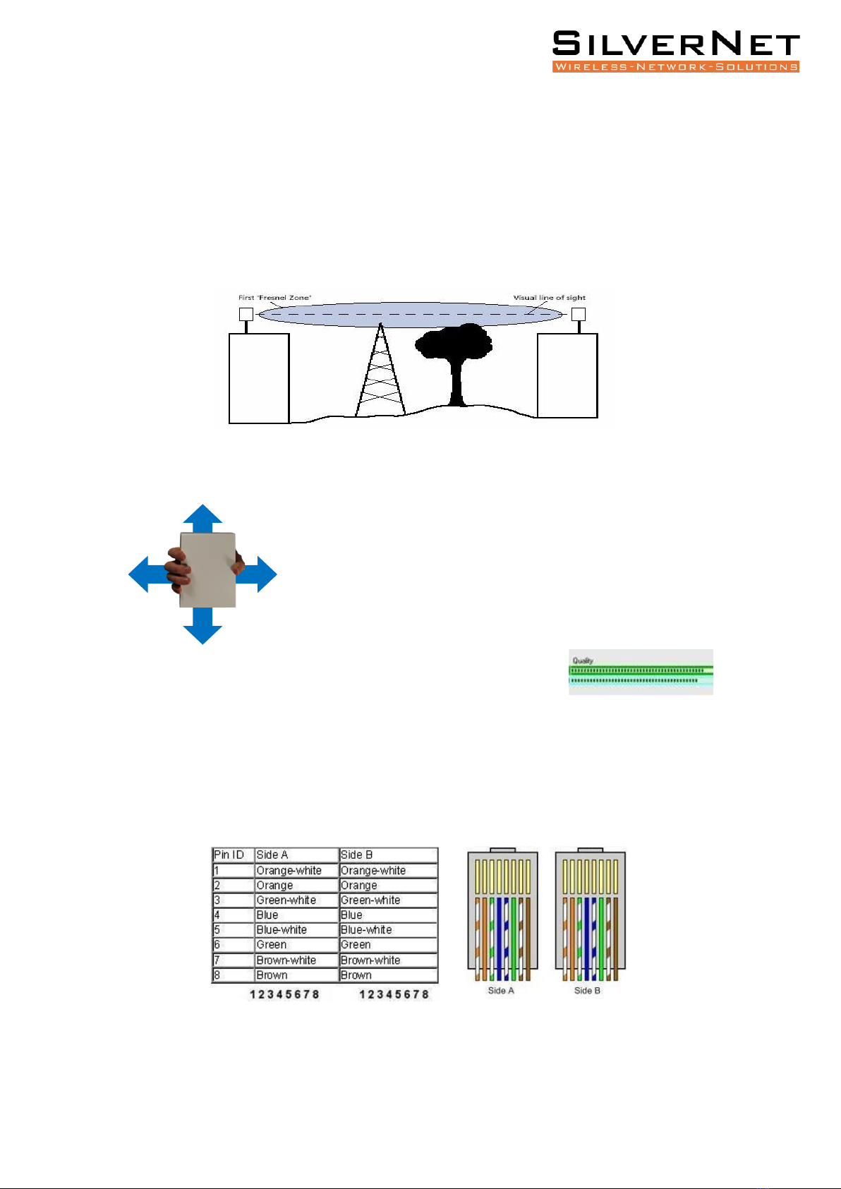
a) Line of Sight –The radios need absolute clear Line-of-Sight to function due to the
frequencies they operate on. If the radios don’t have a complete line of sight then
you will experience poor signals and unstable connections, or potentially no
connection at all.
b) Alignment –If the radios are not aligned correctly then the signal quality will reflect
this.
Slowly rotate the radio from side to side and then up and down until you
achieve the best signal. This is within the ranges of -30 RSSI to -45 RSSI.
You can use the alignment tools within the radio to assist with
this. The quality bar within SilverView gives you a gauge on the
signal strength. There is a link align tool within the Station’s web page –
enabling this will also turn on the alignment beeper.
c) Power/No Network Connection –If the radios are not powering on from fresh out
of the box then the best course of action is to first check the cat5 cable that you are
using and re-terminate as per below. Ensure that the PoE is plugged in and that the
LEDs are on. We recommend the use of surge protection and always the use of
shielded outdoor data cables for all equipment.

SIL MICRO TG60 Quick Setup Guide
15
d) IP Addresses –Default IP addresses are 192.168.0.228 and 229. Change the IP
address of each radio to suit your needs. Note: If you reset the MICRO TG60, the IP
address will reset back to Default IP address: 192.168.1.1
e) Login Password –The default is set to “admin” and “password”. We recommend
changing this. Use something that you won’t forget, like a job number or project
number. Use this on all radios in the system.
f) Distance –These radios will only operate onto a maximum of 250m, due to the
severe signal drop-off experienced on such high frequencies at this gain. Any
distances larger than the recommended specification will not work.
g) Config Files / Firmware –The default configuration files and latest versions of
firmware can be found on our website under the downloads centre. Upload the
0.228 config onto one radio and the 0.229 config onto the other.
h) Manual –Read the manual for detailed explanations of the SilverNet equipment.
This can be downloaded from our website.
http://www.silvernet.com/support/downloads-centre/
i) Youtube –Training videos are available to watch on YouTube.
https://www.youtube.com/user/SilverNetLTD
Other manuals for MICRO TG60
1
Table of contents
Other SilverNet Network Hardware manuals


Popular Network Hardware manuals by other brands

Arista
Arista CCA-ETM-Q12 quick start guide

Simons Voss Technologies
Simons Voss Technologies SmartBridge manual

Connect Tech
Connect Tech Rudi-AGX user guide

ADTRAN
ADTRAN SHDSL NxNTU Installation and Maintenance

Xinje
Xinje XD-2AD2PT-V-ED quick guide

Ruckus Wireless
Ruckus Wireless SmartZone 300 Quick setup guide


Enterasys
Enterasys S Series Upgrade Installation Guide

Advantech
Advantech EKI-1361 user manual

NETGEAR
NETGEAR RNDP600E - ReadyNAS Pro Pioneer Edition NAS... Letter of volatility

Moxa Technologies
Moxa Technologies NE-4100 Series user manual

Paradyne
Paradyne Hotwire 5620 installation instructions

Claxan
Claxan CL-KVM-MPC1700S2-EN user manual