SilverNet MICRO TG60 User manual

1.0 www.silvernet.com
Terragraph Client Node
MICRO TG60
MAX TG60
User Manual

SIL TG60 User Manual Introduction 2
TABLE OF CONTENTS
Introduction............................................................................................................................... 4
Who Should Read This Guide? .............................................................................................. 4
Terragraph Network.............................................................................................................. 4
Supported Products............................................................................................................... 6
Wireless Modes..................................................................................................................... 6
System Requirements............................................................................................................ 6
Packing list................................................................................................................................. 6
The Enclosure and LED indicators ............................................................................................. 7
Getting Started.......................................................................................................................... 8
Overview.................................................................................................................................. 10
Status Overview................................................................................................................... 10
Network Overview............................................................................................................... 13
Link Status Overview ........................................................................................................... 14
Network Configuration............................................................................................................ 15
Uplink Port Role................................................................................................................... 16
LAN Settings......................................................................................................................... 17
Management Port Settings.................................................................................................. 17
Link Configuration ................................................................................................................... 18
System ..................................................................................................................................... 19
Logging................................................................................................................................. 20
User Accounts...................................................................................................................... 21
Maintenance........................................................................................................................ 22
Services................................................................................................................................ 24
SNMP................................................................................................................................... 24
Diagnostics........................................................................................................................... 25

SIL TG60 User Manual Introduction 3
Troubleshooting ...................................................................................................................... 26
System Logs............................................................................................................................. 27
Standards.....................................................................................Error! Bookmark not defined.
Declaration of Conformity.......................................................Error! Bookmark not defined.
Warnings......................................................................................Error! Bookmark not defined.
Radio frequency Interference Requirements..........................Error! Bookmark not defined.
Warranty.................................................................................................................................. 28
Contact SilverNet..................................................................................................................... 28
Copyright Information............................................................................................................. 28
Other SilverNet Products......................................................................................................... 29
Pro Range ............................................................................................................................ 29
Industrial Network Transmission......................................................................................... 29
Intelligent Wi-Fi Solutions ................................................................................................... 29
Industry Leading Technical Support .................................................................................... 29

SIL TG60 User Manual Introduction 4
INTRODUCTION
This User Guide describes the firmware version 1.3 and above which is integrated into all
TG60 Range products provided by SilverNet Ltd.
This guide includes detailed information on MICRO TG60 / MAX TG60 software, including
how to operate and use the management functions of the device. To deploy it as part of a
Terragraph network or as a wireless bridge effectively and ensure trouble-free operation,
you should first read the relevant sections in this guide so that you are familiar with all
software features.
WHO SHOULD READ THIS GUIDE?
This guide is for network administrators who are responsible for operating and maintaining
network equipment. The guide assumes a basic working knowledge of LANs (Local Area
Networks) and the Internet Protocol (IP).
TERRAGRAPH NETWORK
Terragraph is a 60GHz, multi-node wireless Software Defined Network (SDN) that enables
high-speed Internet connectivity in multiple environments. The network operates best in
Line-Of-Sight (LOS) conditions to maximize connectivity.
Terragraph is a distribution level network designed to augment and expand a fibre optic
network. That is, Terragraph is a high-speed backbone network to which other networks are
connected. When combined with fixed access connections or Wi-Fi access points, Terragraph
is a low-cost solution to achieve street-level coverage with high speeds.
A Terragraph network is composed of individual nodes. There are two types of nodes in a
Terragraph network –Distribution Nodes (DNs), such as the BASE TG60 and Client Nodes
(CNs), such as the MICRO TG60. DNs are the backbone of the Terragraph network that
distribute Internet connectivity from one or more fibre optic Points of Presence (PoPs) over
multiple hops to CNs. DNs and CNs are connection points for client networks, wireless access
points, and other customer premise equipment (CPE) to connect to the Internet.

SIL TG60 User Manual Introduction 5
Example of a Terragraph Network
Each node in a Terragraph network is a Layer 3 (L3) router. Nodes route traffic within and
between the Terragraph network and attached access networks using routing information
provided by the Open/R protocol. The over-the-air link protocol between Terragraph nodes
uses a modified version of the Directed Multi-Gigabit (DMG) physical layer (PHY) of the IEEE
802.11ay standard.
Each node uses a multi-element, phased array antenna and advanced beamforming
techniques to form high-quality communication links between nodes using primarily LOS
paths while also using reflection paths.
Links can be formed at distances of up to 80 meters between two MICRO TG60 nodes, and
up to 150 meters between one MICRO TG60 node and one BASE TG60 node. The MAX TG60
is suitable for long-range deployments as its range can reach up to 1500 meters when paired
with one MAX TG60, and up to 700 meters when paired with one BASE TG60.
The multiple propagation paths are called micro-routes, and each micro-route is a potential
communication link between nodes. Each node selects the strongest communication link
from the many possible propagation paths between the nodes. The phased array antenna
allows Terragraph to establish links to mitigate co-channel interference that often prevails in
dense urban environments.
The MICRO TG60 / MAX TG60 is a node that serves as the termination point where service
delivery takes place. It is not a part of the mesh network for distribution but provides
connectivity to a fixed client such as a Wi-Fi Access point (AP) or a fixed connection to a
home or office.

SIL TG60 User Manual Packing list 6
SUPPORTED PRODUCTS
This manual covers all TG60 products listed below:
• MICRO TG60
• MAX TG60
For more information, visit www.silvernet.com
WIRELESS MODES
The TG60 range supports the following wireless modes:
• Bridge Mode
• Terragraph Mode
SYSTEM REQUIREMENTS
• Windows XP - Windows 11, Linux, or Mac OS X
• Web Browser: Mozilla Firefox, Apple Safari, Google Chrome, or Microsoft Internet Explorer
9 (or above)
PACKING LIST
Please check the following items in the package before installing the device
Wireless Radio 1 piece
User manual 1 copy
Cable Gland 2 piece
Mounting bracket 1 piece
Steel-Band Clamp 2 piece
PoE Kit 1 piece
Set of screws 1 piece
Please contact your distributor immediately for any missing or damaged items.

SIL TG60 User Manual The Enclosure and LED indicators 7
THE ENCLOSURE AND LED INDICATORS
#
Name
Description
1
Integrated Pole and
Wall Mounting Plate
Mounting plate containing 4x screw holes and 2x strap holes for
versatile mounting.
2
System LED Indicators
LAN: On (LAN Port Connection), Blinking: (Activity).
Uplink(PoE): On (Uplink PoE Port Active), Blinking (Activity). Slow Blink
during system boot up.
60G: On (60GHz Wireless Link Established), Blinking (Activity).
3
Grounding Screw
For ground wire connection.
4
LAN Port
Provides LAN Connectivity only.
5
Uplink PoE Port
Receives PoE Input from PoE Device and LAN Connectivity.

SIL TG60 User Manual Getting Started 8
GETTING STARTED
This section provides an overview of the device and introduces some basic concepts about
Terragraph networks. It also describes the basic settings required to access the management
interface.
The MICRO TG60 / MAX TG60 offers a user-friendly web-based management interface for
the configuration of all the unit’s features. Any PC directly attached to the unit can access
the management interface using a web browser, such as Internet Explorer 9.x or later,
Mozilla Firefox 32 or later, and Google Chrome 35 or later.
The web interface is accessible via the LAN port or via the Management port (Uplink PoE). To
access the web interface through the LAN port, follow these steps:
1. Connect a PC directly to the unit’s LAN port.
2. Configure the Ethernet adapter on your computer with a static IP address on the
192.168.0.x subnet (for example, IP address: 192.168.0.100 and subnet mask:
255.255.255.0

SIL TG60 User Manual Getting Started 9
3. Enter the default IP address of 192.168.0.228 / 0.229 into the web browser address
bar.
Address
4. Log in to the web interface using default settings:
Username = admin
Password = admin
To access the web interface through the Management port (Uplink PoE), Connect a PC to
the data port of the injector powering the MICRO TG60 / MAX TG60.
If the unit has been reset, it will go to the default IP address of 192.168.1.1. You will need
to change your Ethernet adapter IP address to 192.168.1.x subnet.

SIL TG60 User Manual Overview 10
OVERVIEW
This section describes the basic switch features, along with a detailed description of how to
configure each feature via a web browser. This section includes Status, System and Network.
STATUS OVERVIEW
After logging in to the web interface, the Overview screen is displayed. The Overview screen
shows the basic settings of the device, including system information, memory, and network
status.

SIL TG60 User Manual Overview 11
Hostname The device name configured by the system automatically.
Device Name The device name that can be configured manually.
Serial Number The serial number of the unit.
Firmware Version The software version number.
Local Time The date and local time.
Uptime The length of time the device has been up.
Load Average The last 1-minute, 5-minute, and 15-minute CPU load average.
MAC Address The complete list of MAC addresses of the device and the correspondent
network interfaces: Management Port, LAN, and Radio
Memory The total available memory, how much memory is free, and how much memory is
being used as buffer.

SIL TG60 User Manual Overview 12
Operation Mode The current operation mode —Terragraph or Point-to- point.
Network Behaviour The behaviour of the unit and of the entire Terragraph network. In
Terragraph mode, the behaviour is described as VXLAN Tunnelling or Layer 2 Bridge. Point-
to-point Mode is limited to Layer 2 Bridge.
SIL TG60 User Manual Overview 13
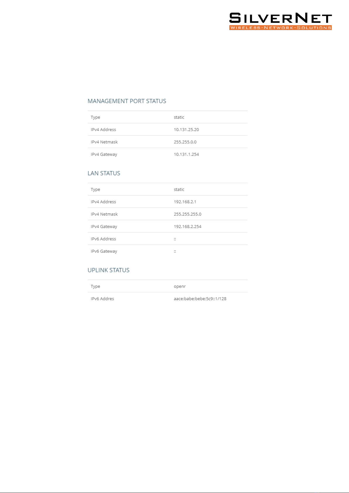
NETWORK OVERVIEW
The Network section displays the IP information for each interface. It includes the
Management Port Status, LAN Status and Uplink Status.

SIL TG60 User Manual Overview 14
LINK STATUS OVERVIEW
Peer MAC Radio MAC address of connected devices.
RSSI Received signal strength indication, this is an indicator of the received signal strength
from the peer. Unit is decibels per milliwatt (dBm).
MCS Modulation and Coding Scheme (MCS) index values supported by the radio.
Channel The working channel.
TX Power The transmission power index. (Range: 6-31)
PER Packet error ratio. The ratio of error packets over received packets on this link.
RX Beam Idx Receiving beam index. The beamforming index that is used for receiving.
TX Beam Idx Transmitting beam index. The beamforming index that is used for transmission.
Note: Beam Idx 29 and 30 are the central-most beams. It is recommended to adjust the
alignment to make beam indexes as central as possible.

SIL TG60 User Manual Network Configuration 15
NETWORK CONFIGURATION
The MICRO TG60 / MAX TG60 has two modes of operation, Terragraph Mode and Point-to-
Point Mode.
When in Terragraph Mode, the MICRO TG60 / MAX TG60 functions as a CPE device (Client
node) providing last-mile, client-side Internet connectivity.
In Terragraph Mode, the MICRO TG60 / MAX TG60 is triggered passively to set up a 60 GHz
link association. The E2E controller (End-to-End controller), which is either embedded in the
BASE TG60 or runs on the Terragraph Network Management System (TG NMS), triggers the
establishment of all links in the defined Terragraph network. The MICRO TG60 listens for the
signal from the E2E controller to set up a link. Thus, users do not have to configure a link on
the MICRO TG60.
After the link between the MICRO TG60 / MAX TG60 and the POP node have been
established, the POP node informs the CN of the network behaviour.
If the POP node is in Terragraph Mode, every node behaves as an IPv6 router, and the
VXLAN between CN and POP is set up automatically. The VXLAN tunnel can forward Layer 2
services (e.g. PPPoE, multicast streaming) over the Terragraph network. On the contrary, if
the POP node is in Bridge Mode, each node behaves as a Layer 2 Bridge.
When the CN is in Point-to-Point mode, it also functions as a Layer 2 bridge. In this mode,
the CN can setup a point-to-point link without the TG NMS or the local controller on the
POP. Point-to-Point Mode supports VLAN transparent and is designed for point-to-point
backhaul links.
Note: When in the same network as a BASE TG60 (DN), MICRO TG60/MAX TG60 must be in
Terragraph mode.

SIL TG60 User Manual Network Configuration 16
UPLINK PORT ROLE
Role Select the function of the Uplink Port (PoE port). It functions as a dedicated
management port by default. This role can be changed to LAN port.

SIL TG60 User Manual Network Configuration 17
LAN SETTINGS
IP Address Mode Configure the LAN interface to be in static IP mode or DHCP mode. In
DHCP mode, it broadcasts a DCHP request in the Layer 2 network when the network
behaviour is set to Layer 2 Bridge. When the network behaviour is VXLAN, it sends a DHCP
request to the core network via the VXLAN tunnel.
Fallback IP The IPv4 address used when a DHCP server is unavailable. Required when the IP
Address Mode is DHCP.
Fallback Netmask The subnet mask used for the Fallback IP address. Required when the IP
Address Mode is DHCP.
IP Address The static IP address. Required when IP Address Mode is Static IP.
Subnet Mask The subnet mask. Required when IP Address Mode is Static IP.
DNS The DNS server IP/IPv6 addresses.
MANAGEMENT PORT SETTINGS
Set IP Address Mode The method used to provide an IP address for the Internet access port.
(Default: DHCP; Options: DHCP, static IP)
Static IP —Configuration options displayed for Static IP are shown in Figure 10.
DHCP —To configure the selected Ethernet interface using a DHCP server, the following
items must be specified.
Fallback IP The IPv4 address used when a DHCP server is unavailable (Default: 192.168.1.20)
Fallback Netmask The subnet mask used for the Fallback IP address (Default: 255.255.255.0)

SIL TG60 User Manual Link Configuration 18
LINK CONFIGURATION
The MICRO TG60 / MAX TG60 allows a point-to-point connection with another CN. Set up
the link by selecting the working channel (1 to 4) and entering the 60GHz radio MAC address
of the other MICRO TG60.
Note Link Configuration is only available when the operation mode is set to Point- to-Point
Mode. You only need to configure a link on one of the two nodes.

SIL TG60 User Manual System 19
SYSTEM
Device Name Configure the device name.
Country Select the installation region to automatically apply country-specific settings
following local standards.
NTP Server Configure the NTP servers’domain name or IP address.
Timezone Choose the appropriate time zone according to Continent/City.
Number of boot retries for switching bootbank The device has dual boot partitions. Set the
number of power sequences before the device switches to the alternative boot bank.
(Default: 5)
Number of boot retries for factory reset Set the number of power sequences that force a
factory reset. (Default: 3)
Note To perform one power sequence plug in the PoE for 5 seconds and unplug it for 1
second. By default, two successive power sequences with complete boot on the third,
triggers the factory reset. Four successive power sequences and a complete boot after that
switches boot banks.

SIL TG60 User Manual System 20
LOGGING
Configure the remote system log server and log properties. Logs contain the configuration,
link, and log information often needed to discover the root cause of a problem.
The device allows you to control the logging of error messages, including the type of events
that are recorded and configure logging to a remote System Log (syslog) server or other
management stations.
System log buffer size Specifies the available memory used for logging of error messages.
(Default: 64 KiB)
External system log server Specifies the IPv4 or IPv6 address of a remote server which will
be sent syslog messages.
External system log server port Specifies the UDP port number used by the remote server.
(Range: 1-65535; Default: 514)
Log output level Use the menu to select the severity of the logs to print to the console. Logs
with the severity level you select and all logs of greater severity print. For example, if you
select Error, the logged messages include Error, Critical, Alert, and Emergency. The default
severity level is Debug(7). The severity can be one of the following levels:
Other manuals for MICRO TG60
1
This manual suits for next models
1
Table of contents
Other SilverNet Network Hardware manuals


Popular Network Hardware manuals by other brands

Matrix Switch Corporation
Matrix Switch Corporation MSC-HD84DEL product manual

United Technologies
United Technologies TruVision NVR 21S quick start guide

Helmholz
Helmholz MQTT Broker manual

Enterasys
Enterasys 6H302-48 user guide

Allied Telesis
Allied Telesis AT-TN119-A Specifications

Clavister
Clavister SG3200 Series Getting started guide


