SilverNet MICRO 95 User manual

MICRO 95/240 LITE 95/240/500
MAX 95/240/500/1000 BASE 500/ACCESS 1200
BASE 500 90/AP 1200 90 BASE 500 360/AP 1200 360
Pro Range
Installation Guide
Version 1 (31/05/2017)

Radio frequency Interference
Requirements
The operation of this device in the 5.15 GHz to 5.25 GHz frequency range is
restricted to indoor use. FCC regulations require this product to be used
indoors while operating at 5.15 GHz to 5.25 GHz to reduce the potential for
harmful interference. However, the operation of this device in the 5.25 GHz
to 5.35 GHz frequency range is allowed for both indoor and outdoor use.
High power radars are allocated as primary users of the 5.25 GHz to 5.35
GHz and 5.65 GHz to 5.85 GHz bands. These radar stations can cause
interference with and/or damage to this device.
FCC Warning
This equipment has been tested and found to comply with the limits for a
Class B digital device, pursuant to Part 15 of the FCC Rules. These limits are
designed to provide reasonable protection against harmful interference in a
residential installation. This equipment generates, uses, and can radiate
radio frequency energy and, if not installed and used in accordance with the
instructions, may cause harmful interference to radio communications. No
guarantee exists that interference will not occur in a particular installation. If
this equipment does cause harmful interference to radio or television
reception (determined by turning the equipment off and on), the user is
encouraged to try to correct the interference by one or more of the following
measures:
•Reorient or relocate the radio/TV receiving antenna.
•Increase the separation between the equipment and the radio/TV
receiver.
•Connect the equipment into an outlet on a circuit different from that
to which the radio/TV receiver is connected.
•Consult the dealer or an experienced radio/TV technician for help.
Modifications made to the product, unless expressly approved by
SilverNet Limited, could void the user’s authority to operate the
equipment.

RF Exposure Requirements
To ensure compliance with FCC RF exposure requirements, the antenna used
for this device must be installed to provide a separation distance of at least
30 cm from all persons and must not be co-located or operating in
conjunction with any other antenna or radio transmitter. Installers and
end-users must follow the installation instructions provided in this user
guide.
CE Statement
The PRO RANGE system is intended to be used by suitably trained
individuals or organisations who are familiar with the requirements of the
R&TTE directive. In particular the client must ensure that appropriate
antennas and transmit power levels are selected to ensure that all power
limits are met. Hereby, SilverNet Limited declares that this device is in
compliance with the essential requirements and other relevant provisions of
the R&TTE Directive 1999/5/EC. However, the use of the following warning
symbol
Means that this equipment is subject to restrictions of use in certain
countries and selection of the correct country of operation (country code)
will ensure that the device operates only on the frequencies permissible
within that country. It is also the operator’s responsibility to ensure that
appropriate licenses have been sought when operating on licensed
frequencies, for example UK Band C, 5725-5850 MHz
Copyright Information
Copyright ©2017 all rights reserved. No part of this publication may be
reproduced, adapted, stored in a retrieval system, translated into any
language, or transmitted in any form or by any means without the written
permission of the supplier

Contents
Radio frequency Interference Requirements.....................................2
FCC Warning.........................................................................................................................2
RF Exposure Requirements.............................................................................................3
CE Statement.......................................................................................................................3
Copyright Information ......................................................................................................3
Declaration of Conformity..............................................................................5
Introduction ...........................................................................................................6
Features and Benefits.......................................................................................................7
Installation .............................................................................................................8
Package list...........................................................................................................................8
Prepare the radio unit to mount to a pole ................................................................9
Device Panel Views and Descriptions...................................................11
Antenna Alignment ..........................................................................................................12
Installation Direction.......................................................................................................13
Mount the Unit on a Pole ...............................................................................................13

Declaration of Conformity
SilverNet Limited declares the following:
Product Name: PRO RANGE
Model No: MICRO 95/LITE 95/MAX 95/MICRO 240/LITE 240/MAX 240/LITE
500/MAX 500/BASE 500/MAX 1000/AP 1200 conforms to the following Product
Standards:
This device complies with the Electromagnetic Compatibility Directive (89/336/EEC)
issued by the Commission of the European Community. Compliance with this
directive implies conformity to the following European Norms (in brackets are the
equivalent international standards.)
Electromagnetic Interference (Conduction and Radiation): EN 55022 (CISPR
22)
Electromagnetic Immunity: EN 55024 (IEC61000-4-2, 3, 4, 5, 6, 8, 11)
Low Voltage Directive: EN 60 950: 1992+A1: 1993+A2: 1993+A3: 1995+A4:
1996+A11: 1997.
Therefore, this product is in conformity with the following regional
standards: FCC Class B: following the provisions of FCC Part 15 directive, CE
Mark: following the provisions of the EC directive.
SilverNet Limited also declares that:
The wireless card in this product complies with the R&TTE Directive (1999/5/EC)
issued by the Commission of the European Community. Compliance with this
directive implies conformity to the following:
EMC Standards: FCC: 47 CFR Part 15, Subpart B, 47 CFR Part 15, Subpart C
(Section 15.247); CE: EN 300 328-2, EN 300 826 (EN 301 489-17)
Therefore, this product is in conformity with the following regional
standards: FCC Class B: following the provisions of FCC Part 15 directive, CE
Mark: following the provisions of the EC directive.

Introduction
The high-performance PRO RANGE (AP) is designed for enterprise and public
access applications. Embedded with the Atheros chipset, it boasts network
robustness, stability and wider network coverage. Based on 802.11n/802.11ac
specification, the PRO RANGE supports high-speed data transmission of up to
1167Mbps.
The access point is capable of operating in different modes, which makes it
suitable for a wide variety of wireless applications, including long-distance
deployments.
Designed with dual polarization high gain antenna it offers a compact, rugged
design for outdoor installation and excellent performance.
Moreover, its integrated Power over Ethernet (PoE) allows the access point to be
used in areas where power outlets are not readily available.
To protect your security and privacy, the PRO RANGE is armed with many
enhanced and latest wireless security features such as IEEE 802.11i standards,
MAC Address Filtering, IEEE 802.1x Authentication and AES/TKIP & 64/128-bit
WEP (Wired Equivalent Privacy) to ensure privacy for the heterogeneous mix of
users within the same wireless network.
The PRO RANGE also incorporates a unique set of advanced features such as:
Virtual AP to deliver multiple services; Long-Range parameter fine-tuning which
provide the access point with the ability to auto-calculate parameters such as
slot time, ACK time-out and CTS time-out to achieve a longer range.

Features and Benefits
➢Data rate 802.11ac up to 866Mbps
➢Data rate 802.11n/a/b/g up to 300Mbps
➢IEEE 802.11ac & IEEE 802.11n/a compatible
➢MAC address control
➢Easy to install and friendly to use, just plug and play
➢Provides Web-based configuration utility
➢Compact design with lightweight, compact size, and low power consumption
➢Supports Power over Ethernet
➢Built in Dual Polarized MIMO Antenna
➢Weatherproof, can be used outdoors
➢WPA/WPA2

Installation
Package list
PRO RANGE Radio
POE Power Adapter
Mains Power Cable
Mounting Kit
If any of the above items are not included or damaged, please contact your
supplier immediately for support.

Prepare the radio unit to mount to a pole
Unpack the mounting brackets from the box.
Assemble the main part of the bracket using the 2 shortest
bolts.
Put the bracket round the pole, put the last part of the bracket round
the pole and tighten the 2 longer bolts with a spanner to secure the
bracket to the pole. Bolt the unit onto the secure bracket.
*Note
To mount the device to the wall you do not need the last part of the
bracket and the 2 longer bolts.
Connect one end of an RJ45 Ethernet cable to the DATA + Power
port of the Injector and the other end of the cable to the Network
port of the device.
Maximum length of the RJ45 Cat 5 cable is 100 meters.
Connect another RJ45 Ethernet cable to the Network port on the
PoE Injector and the other end to a network device, such as a switch
or to the PC you will use to configure the access point.
PoE power input: Passive PoE (48V DC)
Note: The radio can also be powered from a PoE network switch.

Connect the power adapter in the PoE kit to the main electrical supply and the power plug into the
socket of the injector.
Now, turn on your power supply. The Ethernet LED will light up.
This indicates that the access point is receiving power through the
PoE Injector and that connection between the access point
and your network has been established.
Using a power adapter with a different voltage rating to the specified recommendation will damage
this product.
*NOTE: all the Pro Range products use the same mounting brackets

Device Panel Views and Descriptions
MICRO 95
*Note: This is also relevant for all the Pro Range equipment
Features
Status and Indications
1
Ethernet Link LED
ON: A Network connection has been detected
OFF: No Network connection has been detected
2
75% Signal RX LED
ON: Signal Strength is at 75%
OFF: Signal Strength is not at 75%
3
100% Signal RX and
Diagnostic LED
ON: Signal Strength is at 100%
OFF: Signal Strength is not at 100%
Slow constant Flashing: Device is in diagnostic
mode
4
Ethernet Port
10/100Mbps (1000Mbps on 240 & 500 range)
Ethernet port and PoE power input (48V DC)
4
1
2
3

Antenna Alignment
When aligning the antenna you should examine the physical environment where the
equipment is being installed.
Check for obstructions, available mounting locations, and other factors.
Things such as trees, buildings, and hills, can obstruct the antenna, reducing the
signal strength.
The antenna should be installed at a height above such obstructions, and aligned so
that antennas are directed at each other by taking into account the horizontal angle
and the vertical angle of the antenna signal.
When the antenna is at the optimum alignment, there is less possibility of
encountering interference and of causing interference.
The radios work best when they have line-of-sight. If the radios do not have
line-of-sight then you will get a very poor signal or no signal at all.
If the radios are not aligned correctly the signal quality of the radios will suffer and
you may not receive the throughput you require.

Installation Direction
The directional antenna radiates the signal towards the front of the unit. The
unit should be installed in a position whereby the front of the unit faces the
direction you wish to send the signal to. Therefore the direction you wish to send
the signal has to be considered before going on to the next step of starting to set
up the access point.
Mount the Unit on a Pole
The device is designed to mount to a pole.
The following guidelines will help you choose the best location for your wireless
device:
•Try to place the device in an area where other engineers who may require
access to it, can get to it easily. Consider where the PoE Injector will be.
•Choose an elevated location where trees, buildings and large steel structures
will not obstruct the antenna signals and offers maximum line-of-sight to the
other device.
•Select the appropriate antenna for your environment. You can fine-tune
parameters such as the transmit power and rate aggressiveness to achieve
the best results.

For more guidance please visit our
YouTube channel
www.youtube.com/user/SilverNet
LTD
This manual suits for next models
15
Table of contents
Other SilverNet Wireless Access Point manuals
Popular Wireless Access Point manuals by other brands
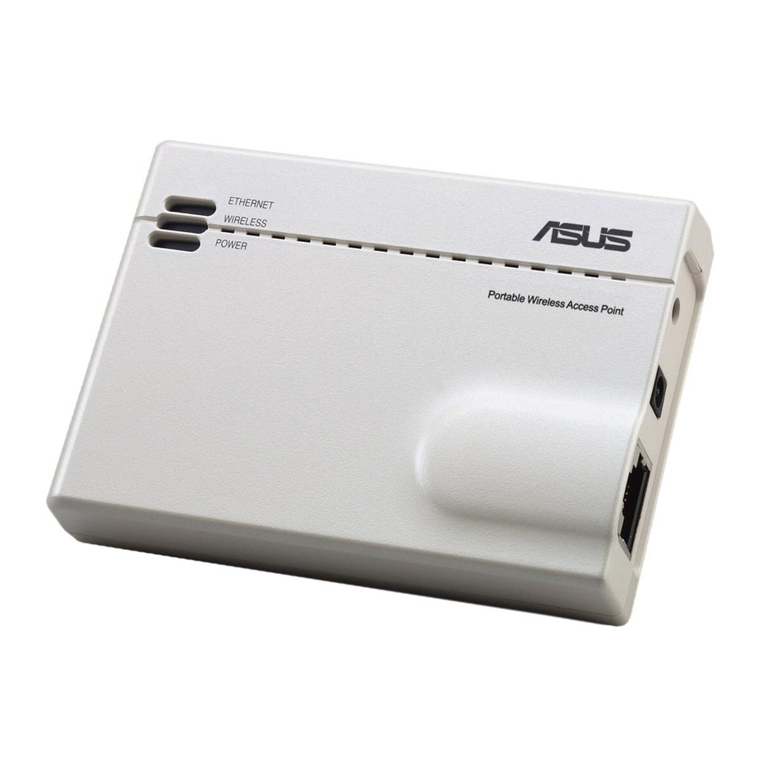
Asus
Asus WL-330GE - Wireless Access Point manual
Cisco MERAKI
Cisco MERAKI MR46E installation guide
Gigawave
Gigawave G-AP-LITE-48 instructions
Cisco
Cisco WAP131 quick start guide
NETGEAR
NETGEAR WG602v4 - Wireless Access Point installation guide
Ruijie
Ruijie RG-AP810-I Hardware installation and reference guide
