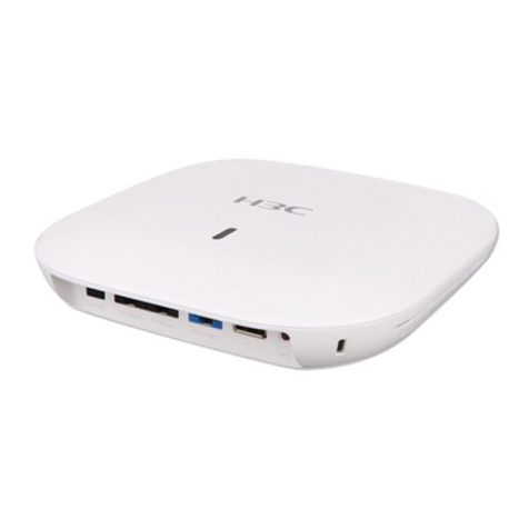
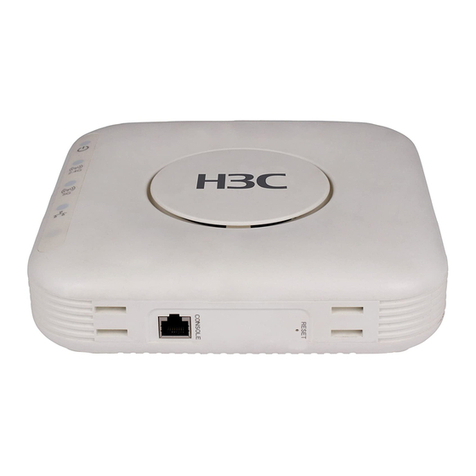
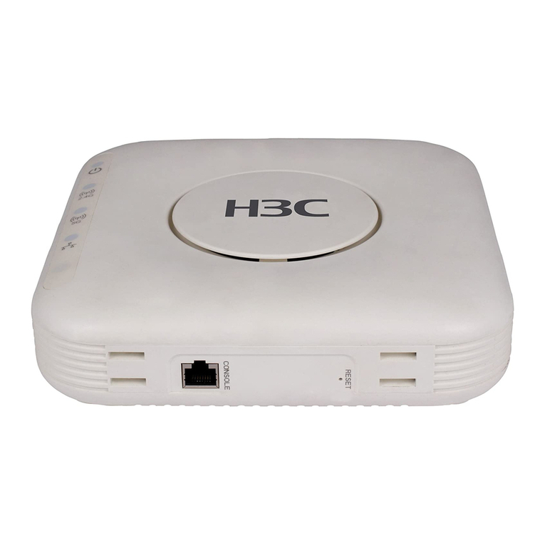
H3C WA4320H-ACN User manual

H3C WA4320H-ACN Access Point
Installation Guide
Hangzhou H3C Technologies Co., Ltd.
http://www.h3c.com
Document version: 6W100-20150626

Copyright © 2015, Hangzhou H3C Technologies Co., Ltd. and its licensors
All rights reserved
No part of this manual may be reproduced or transmitted in any form or by any means without prior
written consent of Hangzhou H3C Technologies Co., Ltd.
Trademarks
H3C, , H3CS, H3CIE, H3CNE, Aolynk, , H
3
Care, , IRF, NetPilot, Netflow,
SecEngine, SecPath, SecCenter, SecBlade, Comware, ITCMM and HUASAN are trademarks of
Hangzhou H3C Technologies Co., Ltd.
All other trademarks that may be mentioned in this manual are the property of their respective owners
Notice
The information in this document is subject to change without notice. Every effort has been made in the
preparation of this document to ensure accuracy of the contents, but all statements, information, and
recommendations in this document do not constitute the warranty of any kind, express or implied.
Environmental protection
This product has been designed to comply with the environmental protection requirements. The storage,
use, and disposal of this product must meet the applicable national laws and regulations.

Preface
The
H3C WA4320H-ACN Access Points Installation Guide
guides you through the installation of your AP.
It covers product overview, preparing for installation, installing the AP, logging in to the AP, and LEDs and
ports.
This preface includes the following topics about the documentation:
•Audience.
•Conventions.
•Obtaining documentation.
•Technical support.
•Documentation feedback.
Audience
This documentation is intended for:
•Network planners.
•Field technical support and servicing engineers.
•Network administrators working with the WA4320H-ACN
APs.
Conventions
This section describes the conventions used in the documentation.
Command conventions
Convention Descri
p
tion
Boldface Bold text represents commands and keywords that you enter literally as shown.
Italic
Italic
text represents arguments that you replace with actual values.
[ ] Square brackets enclose syntax choices (keywords or arguments) that are optional.
{ x | y | ... }
Braces enclose a set of required syntax choices separated by vertical bars, from which
you select one.
[ x | y | ... ]
Square brackets enclose a set of optional syntax choices separated by vertical bars, from
which you select one or none.
{ x | y | ... } *
Asterisk marked braces enclose a set of required syntax choices separated by vertical
bars, from which you select at least one.
[ x | y | ... ] *
Asterisk marked square brackets enclose optional syntax choices separated by vertical
bars, from which you select one choice, multiple choices, or none.
&<1-n>
The argument or keyword and argument combination before the ampersand (&) sign can
be entered 1 to n times.
# A line that starts with a pound (#) sign is comments.

GUI conventions
Convention Descri
p
tion
Boldface
Window names, button names, field names, and menu items are in Boldface. For
example, the New User window appears; click OK.
> Multi-level menus are separated by angle brackets. For example, File > Create > Folder.
Symbols
Convention Descri
p
tion
WARNING
An alert that calls attention to important information that if not understood or followed can
result in personal injury.
CAUTION
An alert that calls attention to important information that if not understood or followed can
result in data loss, data corruption, or damage to hardware or software.
IMPORTANT An alert that calls attention to essential information.
NOTE An alert that contains additional or supplementary information.
TIP An alert that provides helpful information.
Network topology icons
Represents a generic network device, such as a router, switch, or firewall.
Represents a routing-capable device, such as a router or Layer 3 switch.
Represents a generic switch, such as a Layer 2 or Layer 3 switch, or a router that supports
Layer 2 forwarding and other Layer 2 features.
Represents an access controller, a unified wired-WLAN module, or the access controller
engine on a unified wired-WLAN switch.
Represents an access point.
Represents a mesh access point.
Represents omnidirectional signals.
Represents directional signals.
Represents a security product, such as a firewall, UTM, multiservice security gateway, or
load balancing device.
Represents a security card, such as a firewall, load balancing, NetStream, SSL VPN, IPS,
or ACG card.
Port numbering in examples
The port numbers in the documentation are for illustration only and might be unavailable on your device.
Obtaining documentation
Access the most up-to-date H3C product documentation on the World Wide Web
at http://www.h3c.com.
Click the following links to obtain different categories of product documentation:
[Technical Documents]—Provides hardware installation, software upgrading, and software feature
configuration and maintenance documentation.
[Products & Solutions]—Provides information about products and technologies, as well as solutions.
[Software Download]—Provides the documentation released with the software version.
Technical support
servic[email protected]
http://www.h3c.com
Documentation feedback
You can e-mail your comments about product documentation to info@h3c.com.
We appreciate your comments.

i
Contents
Product overview ·························································································································································· 1
Preparing for installation ············································································································································· 2
Safety recommendations ········································································································

1
Product overview
A n H 3 C WA 432 0 H - AC N A P c a n a c t a s a f i t A P t o c o o p e ra t e w i t h w i re l e s s s wi t c h es o r a c c e s s c o n t ro l l e r s
to provide wireless access for WLAN users. The network settings are configured on the wireless switches
or access controllers. The H3C WA4320H-ACN can also act as a fat AP to provide wireless access for
WLAN users.
Table 1 H3C WA4320H-ACN specifications
Item S
p
ecification
Protocol IEEE 802.11a/b/g/n/ac
Radio interfaces Two
Built-in antennas
•2.4 G antenna: gain 2 dBi
•5 G antenna: gain 2 dBi
Power consumption 10 W
Dimensions (H × W × D) 150 × 86 × 35 mm (5.91 × 3.39 × 1.38 in)
Weight 240 g (8.47 oz)

2
Preparing for installation
Safety recommendations
W
ARNING!
Only qualified personnel can install and remove the AP and its accessories. You must read all safety
instructions supplied with the AP before installation and operation.
To avoid possible bodily injury and equipment damage, read the following safety recommendations

3
One M2.9 × 4 anti-theft screw
MAC address label
Installation tools and equipment
When installing the AP, you may need the following tools. Prepare these tools and equipment yourself.
Wire-stripping pliers Phillips screwdriver Torx screwdriver Crimping pliers

4
Installing the AP
Figure 1 Installation flowchart
Check before installation
Before installing an AP, perform the following tasks:
•Connect the AP to the power supply and the network. Examine the LEDs to verify that the AP can
operate correctly. For more information about AP LEDs, see “Appendix LEDs and ports.”
•Verify that cabling on the installation site has been completed.
•To ensure the PoE performance, H3C recommends that you use GE interfaces for PoE power supply.
•Record the AP MAC address and serial number marked on the rear of the AP for future use.
Installing the AP
1. Use the M3.5 × 25 screws to secure the wall-mounting bracket to the terminal box.

5
Figure 2 Securing the wall mounting bracket to the terminal box
2. Connect the two cables to the Uplink/PoE In and Pass Through ports on the AP rear.
Figure 3 Connecting cables
NOTE:
The Pass Through ports on rear and bottom of the AP are standard RJ-45 ports. The ports can
connect telephone cables or other cables as required.
3. Align the installation hole in the AP rear with the bottom line of the tab of the wall-mounting
bracket.

6
Figure 4 Aligning the installation hole with the tab
4.

7
Figure 5 Securing the AP to the wall-mounting bracket
Connecting the AP to the power supply
You can power the AP with local power or by using PoE.
Check before power-on
Check the following items before powering on the AP:
•The power supply is reliably grounded when the AP uses local power supply.
•The PoE power supply is reliably grounded when the AP uses PoE power supply.
Connecting PoE power supply
Use an Ethernet cable to connect the Ethernet interface on the AP to an interface on a switch that supports
Po E.
Connecting local power supply
NOTE:
The AC/DC adapter and power cord are user-supplied.

9
Verifying network connection for the fit AP
All settings of the fit AP are configured on the AC. Use the display wlan ap all command on the AC that
connects to the fit AP. If the AP status is R/M, the AP is connected to the network.
<AC> display wlan ap all
Total Number of APs configured : 1
Total Number of configured APs connected : 1
Total Number of auto APs connected : 0
AP Profiles
State : I = Idle, J = Join, JA = JoinAck, IL = ImageLoad
C = Config, R = Run, KU = KeyUpdate, KC = KeyCfm
--------------------------------------------------------------------------------
AP Name State Model Serial-ID
--------------------------------------------------------------------------------
ap1 R/M WA4320H-ACN 219801A0P79147G00035
-------------------------------------------------------------------------------
Verifying network connection for the fat AP
Use the ping command on the fat AP to ping the uplink network device. If the ping operation succeeds,
the AP is connected to the network successfully.

10
Logging in to the AP
This section applies only when the AP acts as a fat AP. When the AP acts as a fat AP, you can log in to
the AP through Telnet or Web to configure the AP. Before you log in to the fat AP through Telnet or Web,
obtain the IP address of the AP first.
Logging in through Telnet or Web
By default, Telnet login and Web login are enabled. You can log in to the AP by using the following
default login information:
•Username—admin.
•Password—h3capadmin.
•IP address of VLAN-interface 1 of the AP—192.168 .0.50 with subnet m ask 255.255.255.0.

11
Appendix LEDs and ports
LEDs
Figure 7 LEDs on the AP
(1) Power LED (2) Radio LED
(3) Ethernet uplink LED (4) Ethernet downlink
LEDs
Table 3 LED description
Power LED Ethernet
u
p
link LED Radio LED Ethernet
downlink
LED
Description
Steady off Steady off Steady off Steady off
The AP is not powered up or the LEDs are
turned off by commands.
Steady orange Steady off Steady off Steady off Faults occur during the AP initiation.
Flashing green
(0.5 Hz)
Any status Steady off Any status The AP is starting up.
Flashing green
(1 Hz)
Steady off Steady off Steady off The AP is obtaining its IP address.
Flashing green in turn Steady off
The AP has obtained its IP address and is
searching for ACs.
Steady green Flashing green in turn Steady off
The AP found an AC and is registering on
the AC.
Flashing green in turn Steady off Steady off
The AP is performing the Ethernet uplink
negotiation.
Steady green Steady off Any status Any status
The Ethernet uplink port is not connected
with a network cable or has no traffic.
Steady green
Flashing
green
Any status Any status
The Ethernet uplink port is sending or
receiving data at 1000 Mbps.

12
Power LED Ethernet
u
p
link LED Radio LED Ethernet
downlink
LED
Description
Steady green
Flashing
orange
Any status Any status
The Ethernet uplink port is sending or
receiving data at 100 Mbps.
Steady green Any status Steady off Any status No client exists on the radio interface.
Steady green Any status
Flashing
green
Any status Clients exist on the 2.4G radio interface.
Steady green Any status
Flashing
orange
Any status Clients exist on the 5G radio interface.
Steady green Any status
Alternating
green and
orange
Any status
Clients exist on the 2.4G and 5G radio
interfaces.
Steady green Any status Any status Steady off
The Ethernet downlink port is not
connected with a network cable or has no
traffic.
Steady green Any status Any status Flashing green
The Ethernet downlink port is sending or
receiving data at 1000 Mbps.
Steady green Any status Any status
Flashing
orange
The Ethernet downlink port is sending or
receiving data at 100 Mbps.

13
Figure 8 Ports on the AP
(1) 10/100/1000 Mbps Ethernet downlink port
(2) PassThrough port
(3) 10/100/1000 Mbps Ethernet uplink
port
(4) PassThrou
g
h port
Table 4 Port description
Port mark Standards and
p
rotocols
Descri
p
tion
LAN1 to 3
•IEEE802.3
•IEEE802.3u
•10/100/1000 Mbps Ethernet copper ports.
•Act as downlink ports.
•Numbered GE1/0/2 to GE1/0/4 in the
configuration.
Uplink,PoE In
•IEEE802.3
•IEEE802.3u
•IEEE802.3af
•10/100/1000 Mbps Ethernet copper port
•Supports PoE.
•Acts as an uplink port.
•Numbered GE1/0/1 in the configuration.
PassThrough
•IEEE802.3
•IEEE802.3u
The ports are used to connect the telephone
cables or RJ-45 cables.
DC 48V N/A
The port receives +48 VDC power from the local
supply.

14
Index
A
accessories for AP installation, 2
AP
installation, 4, 4
installation accessories, 2
LEDs, 11
logging, 10
ports, 11
Tel n e t ac c e ss, 10
W
eb access, 10
C
check after power-on, 8
check before installation, 4
check before power-on, 7
connecting
local power supply, 7
network, 8
P
oE power supply, 7
power supply, 7
E
electrical
connecting local power supply, 7
connecting PoE power supply, 7
connecting power supply, 7
environment
site humidity, 2
site temperature, 2
equipment needed for installation, 3
H
hardware
AP installation, 4, 4
port technical specifications, 12
humidity (installation site), 2
I
installing
AP, 4, 4
equipment, 3
safety recommendations, 2
site humidity, 2
site temperature, 2
tools, 3
L
LED
technical specifications, 11
local power supply
AP, 7
logging
AP, 10
logging through Telnet
AP, 10
logging through Web
AP, 10
login
AP, 10
N
network connection verification
fat AP, 9
fit AP, 9
networking
AP, 8
P
P
oE power supply
AP, 7
port
technical specifications, 12
post-power-on
check, 8
power supply
AP, 7
pre -installation
check, 4
preparing for installation, 2
pre -power-on
check, 7
procedure
connecting AP to network, 8
Other manuals for WA4320H-ACN
2
Table of contents
Other H3C Wireless Access Point manuals

H3C
H3C WA530X User manual

H3C
H3C WA Series User manual

H3C
H3C WA4330-ACN User manual

H3C
H3C WA2210-AG User manual

H3C
H3C WA530 Instruction Manual

H3C
H3C WA4320-ACN User manual

H3C
H3C WA3610i-GN User manual

H3C
H3C WA5530i User manual

H3C
H3C WA5510E-T Operating and maintenance manual

H3C
H3C WA6528X-E User manual