Silvio cruzbike User manual

Silvio Assembly Manual Page 1
Silvio V2.0 Assembly Instrucons
support@cruzbike.com
SilvioAssemblyNotesV5.0
1. General Safety Informaon
WARNING – to avoid serious injuries:
1. If you are unsure about ng, tesng and adjusng
brakes or gearing on a bicycle, you should take
your bicycle to a professional bicycle mechanic for
adjustment. Improperly adjusted brakes or drivetrain
components could cause severe injury or death.
2. If you are unsure of the frame assembly instrucons,
you should take your bicycle to a professional bicycle
mechanic for assembly. An improperly assembled
frame could cause severe injury or death.
3. Aer adjusng the posion of the crank to t the
rider, ensure the front (exible) chainstay is straight,
not held in a curved posion. An improperly adjusted
frame could be damaged by riding and cause severe
injury or death.
Assembly
This instrucon set describes the assembly sequence
but there may be minor dierences in specicaon of
your model.
Adjust to the rider
Adjust to the rider, before ng brake and gear cables.
Sight along the Front Chainstay to verify that it is
straight, not held in a curved posion. Important!
Adding components
Adding components is done to component
manufacturer’s instrucons. This document does not
describe how to t components, however the Silvio
frame provides standard mounng points for standard
road bike components. Adding components can be
easier if you have a bike workstand and the best place
to clamp the frame is on the slider tube.
Silvio Assembly Manual Page 2
2. Preparaon
Aend to the following before commencing
assembly:
• Unpack the items and unwrap them,
except for tube protecon which may be
retained unl the bicycle is ready to be
ridden.
• Idenfy the headset bearings, (do not
unpack them yet). 1
• Idenfy the frameset is complete, by
reference to the parts diagrams on this
and the following pages.
• If you do not have all the parts, stop and
contact sales@cruzbike.com and provide
the part number.
• Obtain a set of metric hex head wrenchs
(also known as allen keys) in sizes 5mm,
4mm, 3mm and 2.5mm.
Note:
If any of the diagrams here are too small,
download the manual from cruzbike.
com, and zoom in. Go to cruzbike.com/
SilvioAssemblyManual.pdf.
1 If the details of aheadsets are new to you,
two of many useful links explaining them are
Sheldon Brown’s authoritave glossary and this
general descripon with diagrams that describe
the Integrated Headset as found on Silvio.
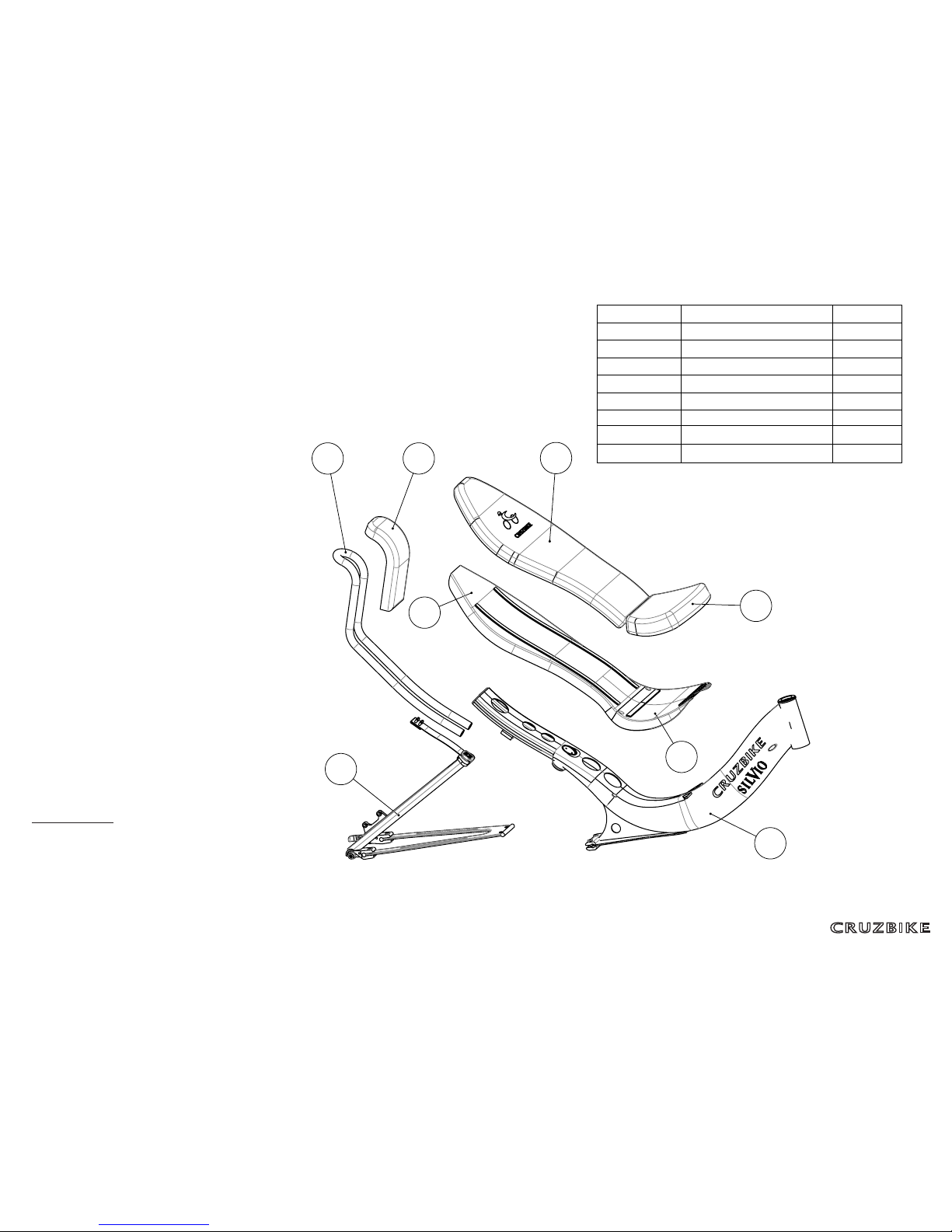
6
5
4
3
1
2
7 8
ITEM NO.
PART NUMBER
QTY.
1
Main Frame
1
2
Rear Triangle
1
3
Seat Pan
1
4
Seat Back
1
5
Seat Pan Cushion
1
6
Seat Back Cushion
1
7
Headrest tube
1
8
Headrest Cushion
1
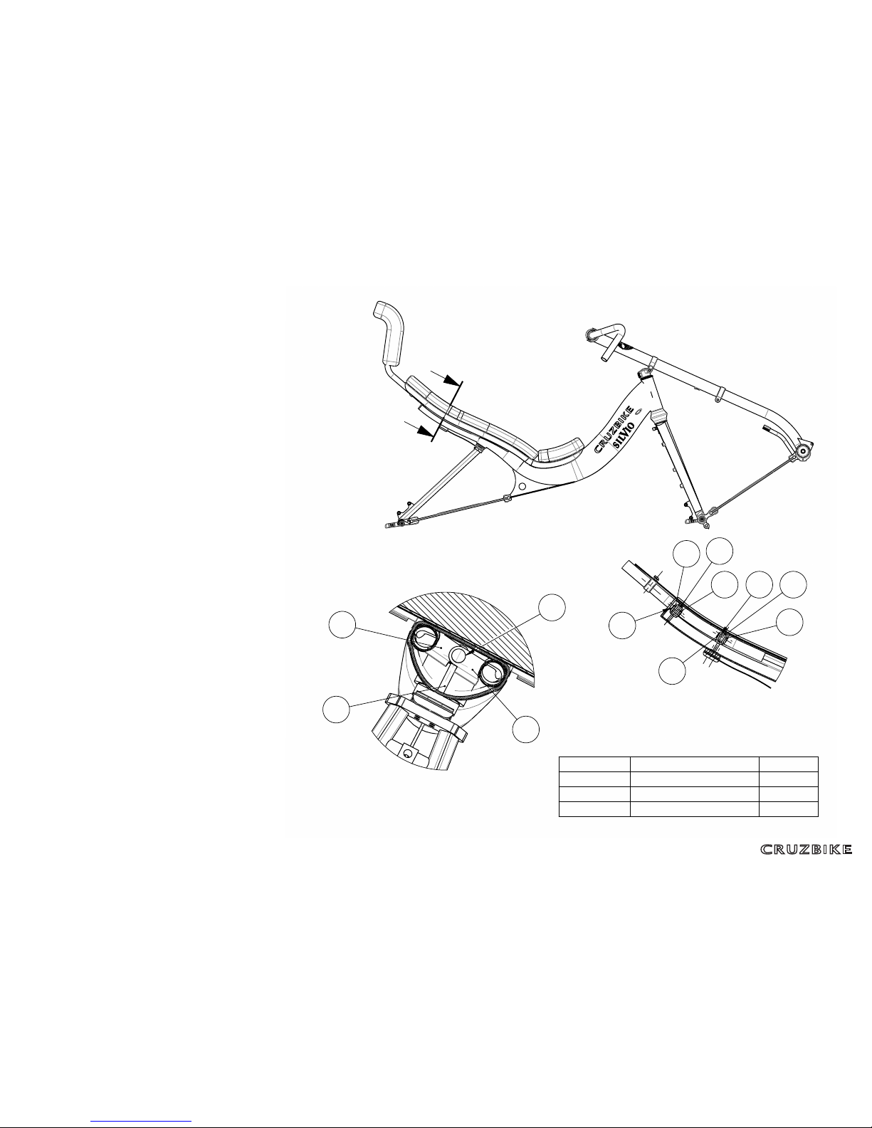
Silvio Assembly Manual Page 3
3. Fit the Headrest
Idencaon
Idenfy the following parts:
• Headrest
• Headrest Cushion
• Two Scissor Jacks
• Main Frame
Insert the headrest legs inside the end of the
Main Frame.
Posion and ghten the scissor jack as
shown.
Apply small pieces of velcro hook to the
inside of the upper curve of the headrest
tubes. This connects with velcro on the
inside of the headrest cushion.
Fit the headrest cushion over the headrest
and secure the velcro
Suspension Block
Screw the suspension Preload Adjustor into
the suspension tube on the underside of the
mainframe.
Insert the Suspension Block into the
suspension tube
H
H
J
SECTION H-H
DETAIL J
SCALE 1 : 2
3
3
1
2
K
L L
M
SECTION L-L
DETAIL M
SCALE 1 : 5
1
1
3
3
3
3
2
2
ITEM NO.
PART NUMBER
QTY.
1
ISO 7380 - M5 x 35
2
2
Barrel Nut
2
3
Wing
4

Silvio Assembly Manual Page 4
4. Fit the seat
Fit the Seat Shells
The Main Frame comes with Velcro, as does
the underside of the Seat.
Bolt the seat pan and seat back together
with the M4 bolts provided.
Place the seat pan
Fit the Cushions
Sck the velcro strips to the Seat Back and
Seat Pan.
Center to center distance for velcro on the
seat pan is 14 cm and on the seat back is 13
cm.
Suspension Block
Screw the suspension Preload Adjustor into
the suspension tube on the underside of the
mainframe.
Insert the Suspension Block into the
suspension tube
130
140
2
1
5
3
4
A
ITEM
NO.
PART NUMBER
QTY.
1
Elastomer part2
1
2
Elastomer
1
3
HR Clamp
2
4
ISO 7380 - M5 x 25 --- 25C
2
5
Hexagon Nut ISO - 4036 - M5 - N
2
54
Bearing cups
2

Silvio Assembly Manual Page 5
5. Prepare the Rear Triangle
Connect the stays together
Bolt the Rear Stay 1 to the Seat Stay 2 with
the raised areas of the Rear Stay facing up.
Add the Suspension Link
Bolt the Suspension Link 3 to the top of the
Seat Stay 2 using the Seat Stay Link Plate 4
and four bolts.
Place Link Buer 10 between the Suspension
Link and the Seat Stay 2.
Next Step
The remaining plate, buer and bolts are
used on the next step.
9
7
1
8
2
6
5
10
3
6
4
10
ITEM NO.
PART NUMBER
QTY.
1
Rear Stay
1
2
Seat Stay
1
3
Ti Link
1
4
Seat Stay Link Plate
1
5
Frame Link Plate
1
6
ISO 7380 - M5 x 12 --- 12C
8
7
CS Washer
16
8
CS Bolt Male
8
9
CS Bolt Female
8
10
Link Buffer
2
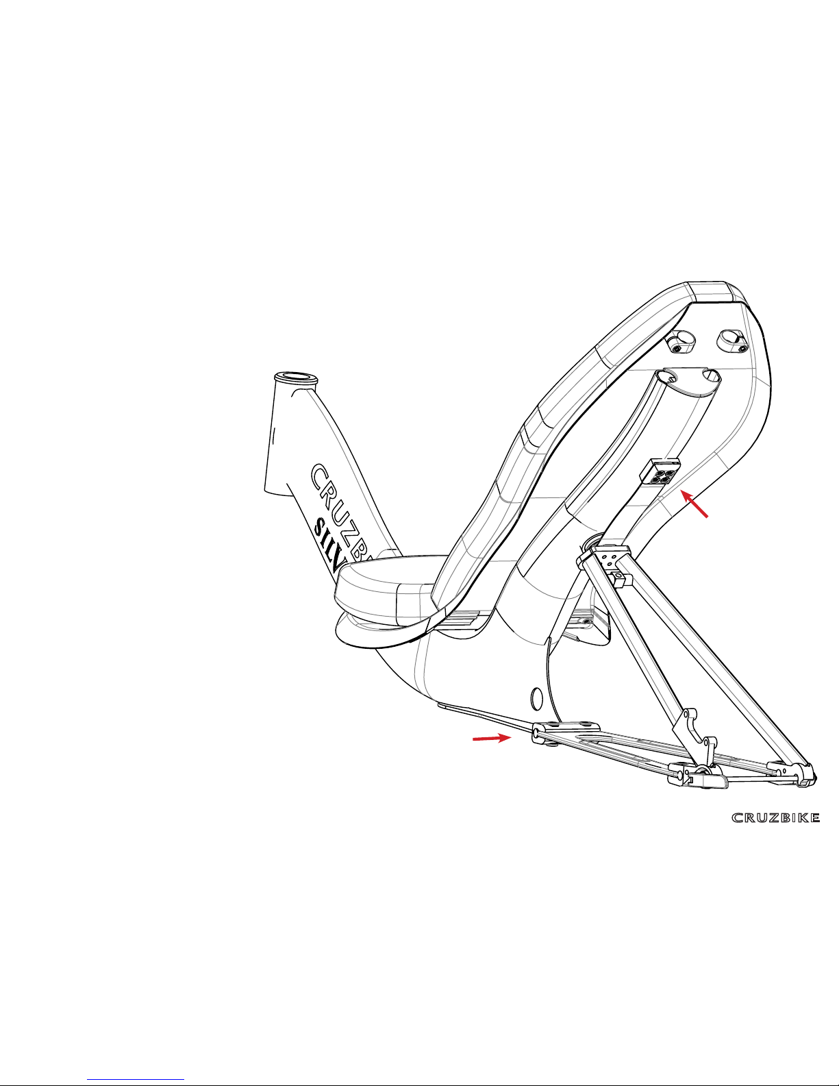
Silvio Assembly Manual Page 6
6. Fit the Rear Triangle to the
Frame
Assemble the Suspension Link to the
frame
1. Slide the Rear Stay to the Frame
Slide the head of the Rear Stay into the
mounng slot on the Frame, checking that
the Suspension Link aligns with the Frame,
then t 2 CS bolts. Tap the head of the Rear
Stay into the slot with a rubber mallet, or
protect it with cloth and use a piece of
wood. You can also wrap the Suspension
Link in a shop rag to protect the frame paint.
2. Fit the Suspension Link
Place Link Buer between the Suspension
Link and the Frame. Bolt the Suspension Link
to the Frame with the Frame Link Plate and
four bolts.
2
1
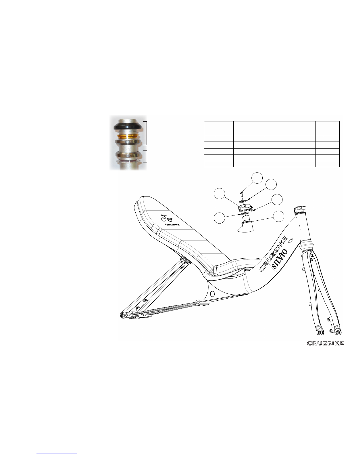
Silvio Assembly Manual Page 7
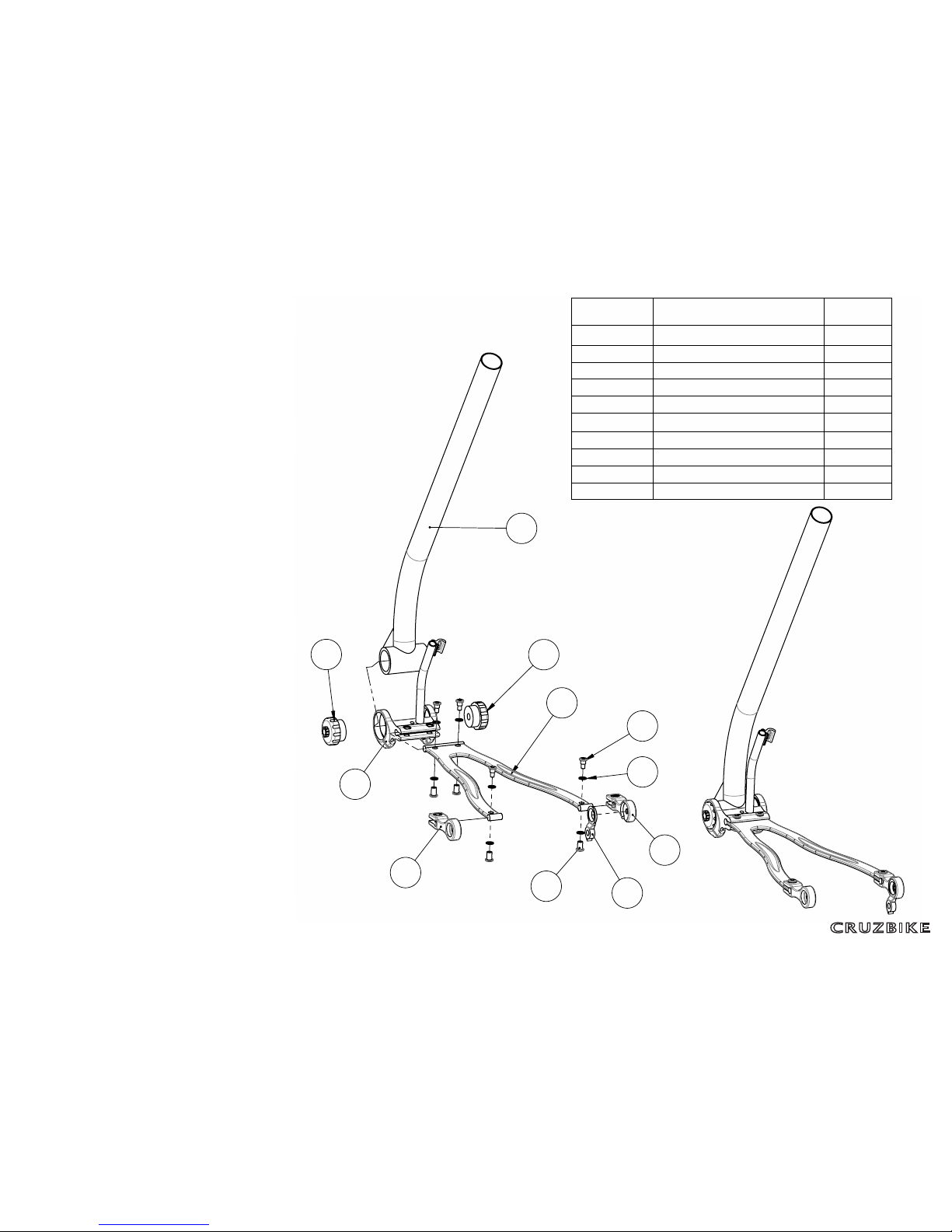
7. Fit the Fork
Note
Instead of a stem, Silvio uses its Pivot Clamp
to clamp the headstack. Note that a surplus
star nut may be included in the headset
bearings, however a star nut has already been
assembled into the fork.
Fit the fork to the frame
Assemble the bearing stack as follows:
1) Place the lower stack onto the fork steerer
2) Slide fork steerer into the frame
3) Add top stack to the fork steerer (Tip: the
dust seal is ght to go on, so lubricate the
inside)
4) Add the Steering Spacer to the fork steerer
5) Add the Pivot Clamp to the fork steerer
6) Check the Pivot Clamp sits at least 2mm
higher than the steerer
7) Add the Steering Cap and and ghten it
down.
Tighten the bearing stack, ensuring you can
sll rotate the Pivot Clamp, as you will need to
align this with the front triangle. Make the two
Pivot Clamp bolts nger ght.
Front Suspension Adjustment
Connect the shock pump to valve on the rear
of the fork crown and adjust to 150psi, working
range is 40 to 200psi.
For detailed instrucons on how to use
the shock pump, see hp://cruzbike.com/
KindShockPumpOperaon.pdf
B
2
5
1
2
43
ITEM NO.
PART NUMBER
QTY.
1
Pivot clamp
1
2
socket head cap screw
3
3
Integrated Headset
1
4
Fork clamp spacer
1
5
Fork Neck Cap
1
The top stack includes:
• Dust seal
• Thin washer
• Gold split ring
• Upper bearing
The lower stack includes
• Lower bearing
• Silver split ring
Silvio Assembly Manual Page 8
8. Assemble the Chainstay to
the Boom
Fit Chainstay to BB Clamp
If you are ng a Chainstay Extension,
aach it now to the Carboyoke Chainstay.
Slide the head of the Chainstay into the slot
on the BB clamp with holes aligned and with
the raised areas of the Chainstay facing up,
and t the CS Bolts.
Fit Boom to the BB Clamps
First, you must obtain the outboard boom
bracket bearing cups. These will come
typically with your crankset . Important!
• Thread the boom bracket bearing cups
in each side, working through the BB
Clamp ring and into the BB shell.
• Slide the Chainstay rings away to the
right to ghten the le bearing cup. And
vice versa. Tighten the bearing cups to
manufacturer’s specicaon.
• Make the BB clamp bolts nger ght only.
Back each bolt o half a turn. Important
- this must be allowed to rotate when
seng leg length! (Fully ghten the Ring
Clamp bolts aer sizing adjustment.)
Fit Dropouts to Chainstay
Fit the dropouts over the ends of the
Chainstay and t the CS Bolts.
The RD hanger sits on the inside of the right
Chainstay dropout, oponally x with glue .
6
5
1
4
7
8
9
2
3
10 10
ITEM NO.
PART NUMBER
QTY.
1
Carboyoke Chainstay
1
2
BB Clamp
1
3
Boom
1
4
CS Dropout Left
1
5
CS Dropout Right
1
6
RD Hanger
1
7
CS Bolt Male
8
8
CS Bolt Female
8
9
CS Washer
16
10
Bearing cups
2
Silvio Assembly Manual Page 9
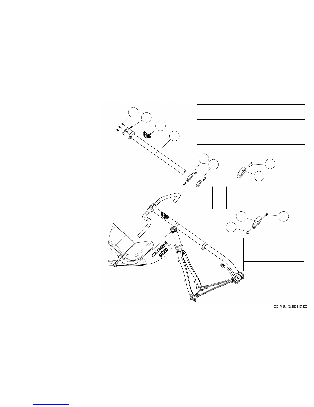
9. Fit the Front Triangle
Slider rst to Pivot Clamp
Insert the Slider through the Slider Clamp.
Rotate the slider so the slot in the end is
underneath.
Connect the Slider Clamp to the Pivot Clamp
using the through pin.
Add the Boom Clamp to the end of the
Slider.
Then Boom & Chainstay
Insert the Boom into the Slider and place the
dropouts over the lugs on the fork dropouts.
Tighten:
• Ring Clamps
• The Headset Cap bolt
• Pivot Clamp bolts
• Slider Clamp
• Boom Clamp
Handlebar
The handlebar ts to the top of the
sliderwith two clamps and four bolts.
Important: Tighten the two Pivot Clamp
bolts aer the front triangle is added.
Finishing touch
Apply the headbadge to the slider.
4
3
2
1
6
5
C
D
E
1
2
3
2
1
ITEM
NO.
PART NUMBER
QTY.
1
Slider Body
1
2
Head Badge
1
3
Handlebar clamp A
2
4
socket head cap screw
4
5
Boom clamp
1
6
Slider clamp
1
ITEM
NO.
PART NUMBER
QTY.
1
Boom clamp
1
2
socket head cap screw
1
ITEM
NO.
PART NUMBER
QTY.
1
Slider clamp
1
2
TL-301 Screw
1
7
Rear Stay
1
Silvio Assembly Manual Page 10
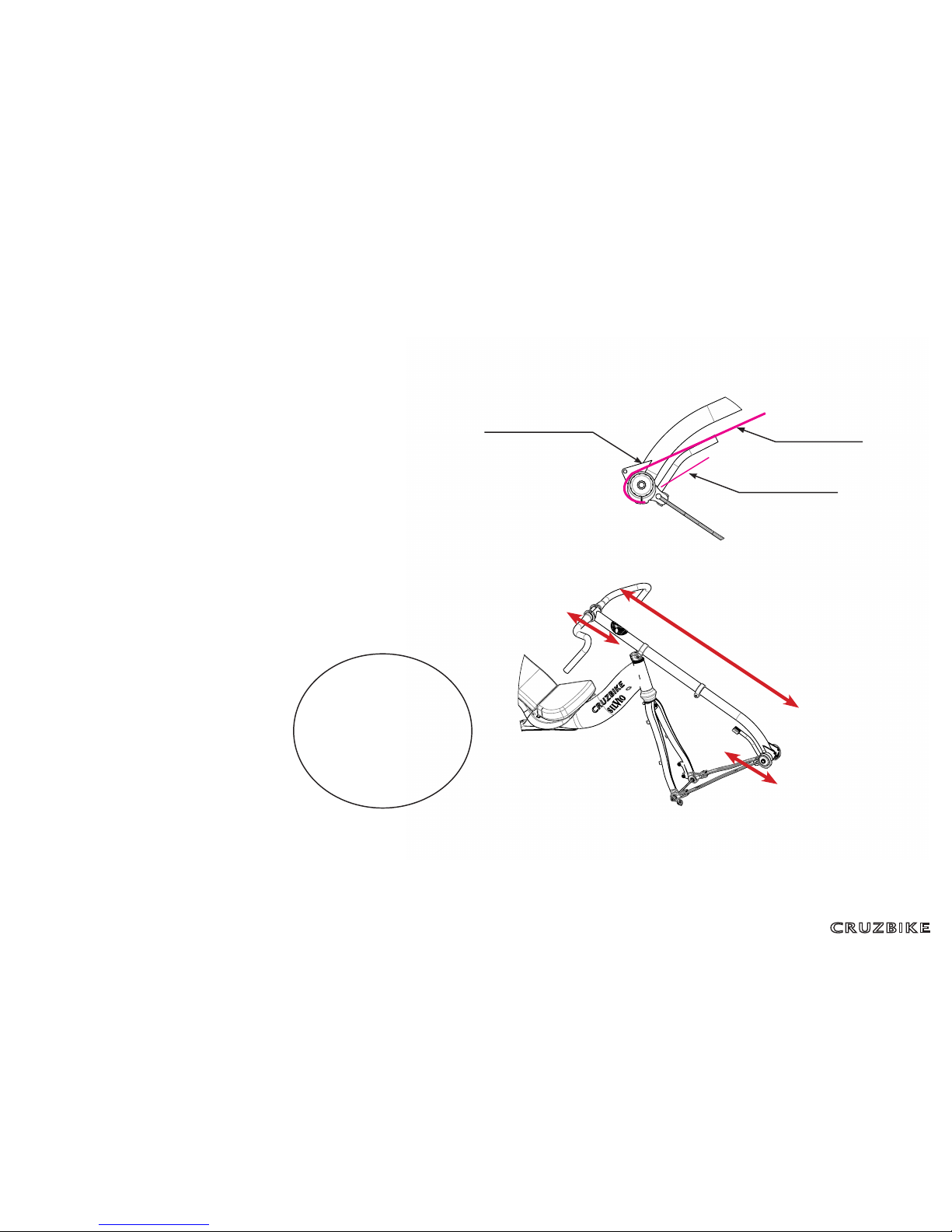
10. Components & Adjustment
FD cable loop
The front derailleur cable should loop the
Boom Bracket in a gear cable housing of
about 250mm, the cable enters the top, runs
over and underneath the BB, and through
the gap between the BB rings:
Rider adjustment
For adjustment to the individual for arm
reach and leg reach, the following are
loosened and ghtened as required:
• Ring Clamps
• Front wheel skewer
• Slider Clamp
• Boom Clamp
Then reghten.
Standard component assembly
Adjust to the rider before running the
cables. Important!
If the wheel axles don’t easily t the
dropouts, use a le to remove excess paint.
All components should be assembled
according to their manufacturer's
instrucons.
Using a stand
If using a stand, place the clamp around the
Slider, between the Slider Clamp and Boom
Clamp, with the front of the bike up so that
the back of the bike hangs down and does
not swing.
F
G
The
rider must
sit low in the seat, to
nd the correct leg reach
adjustment. Final leg and arm
reach adjustment will occur
as the rider gains familiarity
with the riding posion.
First, loosen the
ring clamps and the
skewer. Important!
1
Loosen the slider
clamp and pull slider
to adjust arm/leg
reach.
3
Loosen the boom
clamp and pull
boom to create knee
clearance.
2
Gear Housing Loop Cable to shier
Cable to deraileur
Adjustment Sing on a chair, measure from the oor to the top of your knee (say 58 cm). Add your crank length
(say 17cm) to this (75cm). Add 5cm for knee clearance (80cm)Now adjust the boom clamp [2] to make distance ‘A’
= 80cm. Now adjust leg distance using the Slider clamp [3]. See ‘A’ Any further and adjustments at the slider clamp
[3] will adjust leg length but won’t aect the front derailleur adjustment.
Use the boom
clamp to set this to
accommodate knee
height plus crank
A
Note: Chainstay
must be straight
aer adjustment.
Important!
Table of contents


