Sim-Lab PORSCHE P911 RSR STEERING WHEEL User manual

PORSCHE P911 RSR STEERING WHEEL
VERSION 1.0
Last updated: XX-XX-2022
INSTRUCTION MANUAL

2|2 20
BEFORE YOU START:
Thank you for your purchase. In this manual we will provide you with
the means to get started using your new steering wheel!
Porsche P911 RSR Steering Wheel
Features:
Full billet anodized aluminium construction
80 telemetry controllable RGB LEDs
Motorsports grade electronics
High resolution 5” LCD
Adjustable clutches
Porsche licensed

2 3
| |320 20
Installing drivers
Display drivers
To make the display part of the steering wheel functional, specific drivers are
needed. Drivers can be downloaded from the product page.
Vocore drivers download:
Installation
To install the display drivers, run the downloaded package and specify the location
where to install the drivers:
Press ‘Next’.

4|4 20
Specify the name of the start menu folder:
Press ‘Next’.
Review the settings before installation:
Press ‘Install’.
4 5
| |520 20
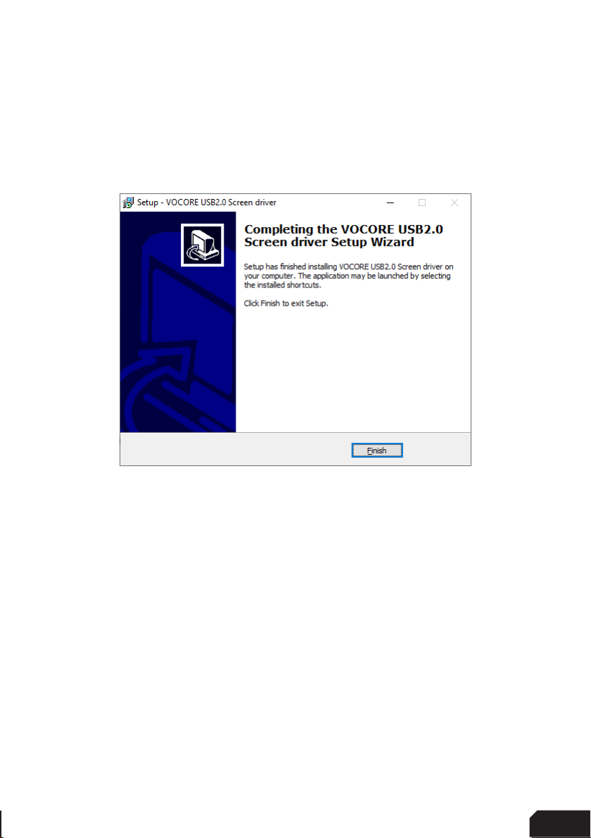
The drivers will install now. Sometimes this can take longer than expected. This
usually means a system restore point is being made and should not hinder
installation.
If it does, unplug the USB cable to the wheel in case it is connected and try again.
Make sure you have administrator rights on your system.
Press ‘Finish’.

6|6 20
SimHub installation
To control the LEDs on the wheel, Simhub can be used.
Download the lastest version of Simhub from https://simhubdash.com
Installation
Unzip the downloaded file and run the setup file. To be able to continue, you will have
to accept the License Agreement:
Press ‘Next’.

6 7
| |720 20
Specify the location where to install the software:
Press ‘Next’.
Make sure all options are checked:
Press ‘Next’.

8|8 20
Press ‘Install’.
After installation press ‘Finish’.
8 9
| |920 20
Initial calibration
Before using the wheel, we recommend to walk through calibration of all paddles
found on the back of the wheel.
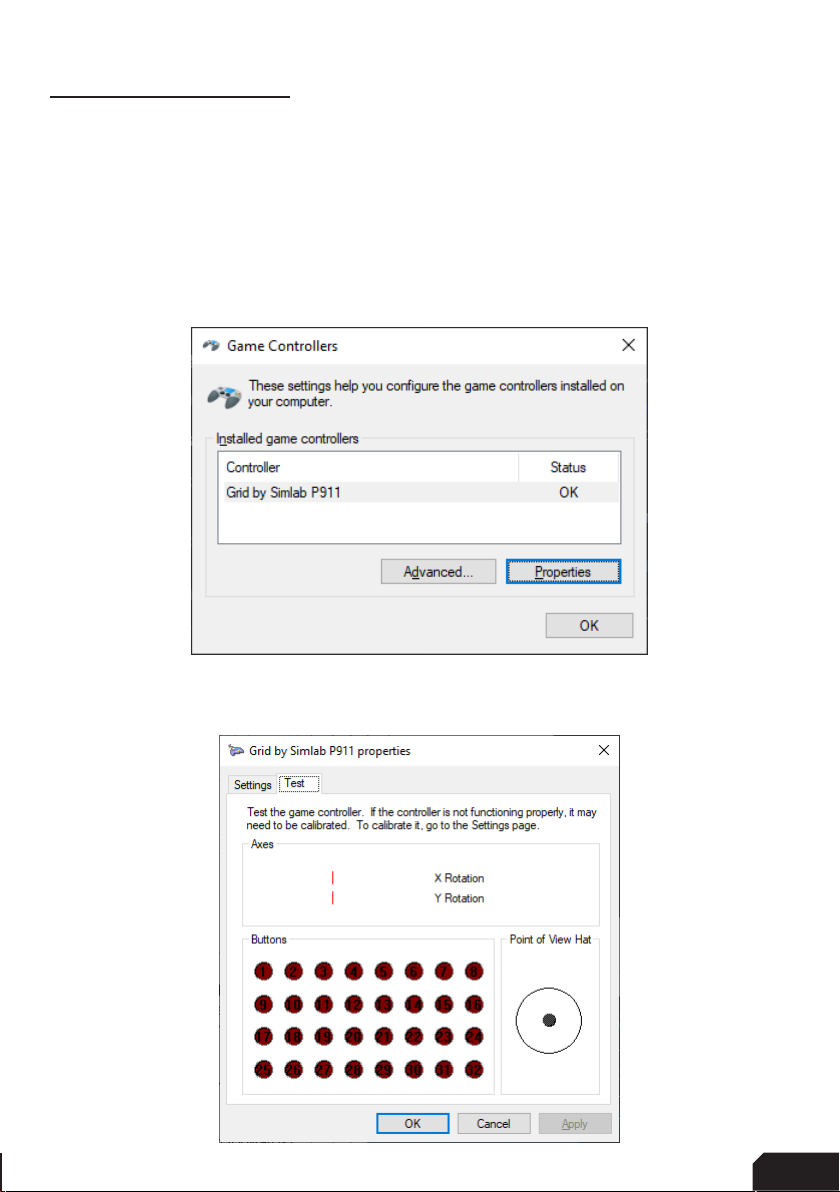
To make this an easier and more visual experience, let’s open the Windows Game
Controller program.
The quickest way to do this is to press the windows-key, type ‘Game Controller’ and
hit ‘enter’ on your keyboard. This will open the Windows Game Controller program.
Select ‘Grid by Simlab P911’ from the list and press ‘Properties’ to access the
properties window.

10 |10 20
A
CM
Calibration Mode
The calibration is a very straightforward process, but first we need to enter the
Calibration Mode on the wheel itself. To activate the wheels’ calibration mode, Press
and Hold the ADJUST (A) button and CALIBRATION MODE (CM) button at the same
time. Keep doing so for at least 5 seconds, until you see BUTTON 1 flashing in the
calibration program. On the wheel itself, the far-left LED will start flashing (red).
Release both buttons when the wheel successfully entered Calibration Mode.
Calibration
Calibration simply consists of depressing all the paddles/mono-arm and holding
them depressed for about a second. After this has been done with all paddles, the
wheels’ firmware has registered the minimum and maximum values for travel. Press
the Adjust (A) button a single time to exit the Calibration Mode.
While the Windows Game Controller program is still running, it is wortwhile to check
all buttons and encoders are working.
All buttons have one input, the front encoders have two (backwards and forwards).
The thumb encoders also have a push functionality in them. As for now, this
windows program only shows you 32 button inputs on screen, we hope this will be
expanded with future windows-updates.

10 11
| |1120 20
Clutch modes and bite-point adjustment
To make the most out of the dual clutches installed, they need to be set-up to your
liking and intended use.
Mode selection
We offer multiple modes for different uses. This can be changed on the fly on the
wheel itself. The three modes are:
• Dual-clutch: The 2 clutch paddles are working as 1 analog input. Left-side is the
adjustable bite-point clutch and the right-side clutch is the master.
Bite-point adjustment available ONLY in this mode.
• Analog: The 2 clutch paddles are working as 2 separate analog inputs.
• Switch: The 2 clutch paddles are working as a momentary switch.
To switch modes, Press and Hold the ADJUST (A) button and Press the mode of
your choice. (1) Dual-Clutch, (2) Analog, (3) Switch. Release both buttons after you
have made a selection.
It is advised you re-calibrate all paddles after changing clutch modes.
A
1
2
3

12 |12 20
Bite-point adjustment
Bite-point adjustment is available only in the DUAL-CLUTCH mode. If you are not
in this mode, please see the previous page how to switch to this mode. Also, it is
important that both paddles are calibrated before adjusting their behavior. Please see
Page 14 before following the steps on this page, if you have not calibrated your clutch
paddles already.
To adjust the bite-point, Press and Hold the ADJUST (A) button and the left clutch
paddle (LC) fully. Next, start by dialing in the bite-point roughly by using the Coarse
(C) adjustment knob, tweak using the Fine (F) adjustment knob.
The Coarse (C) adjustment adjusts in roughly 10% increments, while Fine (F) roughly
does 1% of adjustment. This way you can really dial in your clutches without
compromise.
To make it easier to adjust and know the (exact) percentage of the bite-point, there
is visual feedback (V) on the wheel itself. The RPM LEDs will show red (10% per LED)
while using the Coarse adjustment knob, green (1% per LED) while using the Fine
adjustment knob. You should also be able to see the changes update live, following
the steps on Page 9.
F
V
C
A
LC

12 13
| |1320 20
SimHub configuration
If you haven’t connected the wheel with the supplied USB cable to your computer,
this is required from this point forward.
Activation
To use the display with SimHub, it needs to be enabled:
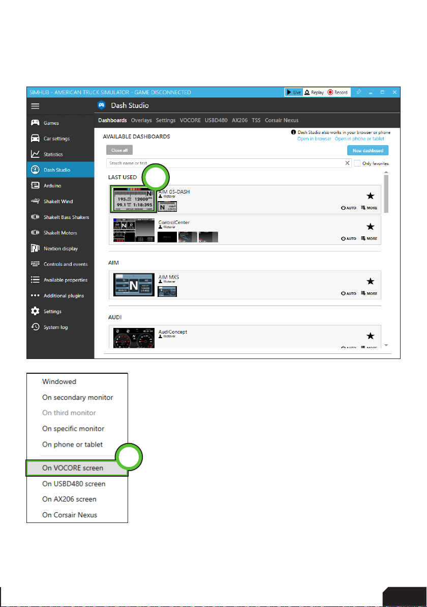
Press ‘Dash Studio’ (1).
1

14 |14 20
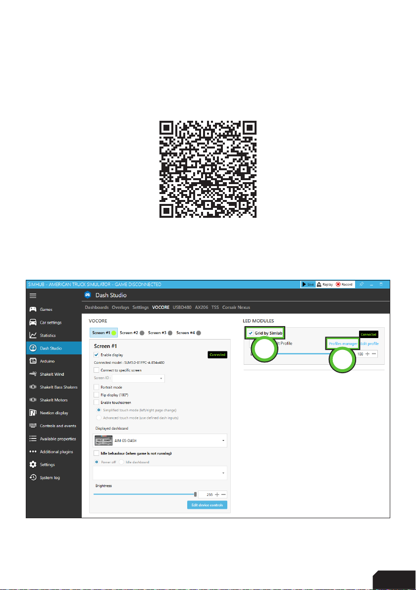
Press ‘VOCORE’ (2).
In the ‘Screen #1’ section, check ‘Enable display’ (3). The ‘Connected’ indicator will
appear on its right-hand side. When the screen is connected, go back to
‘Dashboards’ (4).
3
24
14 15
| |1520 20
Hover over the dashboard you want to display and press ‘Start’ (5).
A popup will appear, select ‘On VOCORE screen’ (6).
The display will now boot using the selected dash.
NOTE: Importing or changing dash profiles is not part of this document. For more
information on that topic, please see the SimHub documentation.
6
5
16 |16 20
Controlling the LEDs
A sample LED profile can be downloaded from the product page.
LED profile download:
To enable or adjust LEDs, navigate back to the ‘VOCORE’ page in ‘Dash Studio’. You
may also refer to Pages 14/15 of this document.
Check the ‘GRID BY SIMLAB’ module (1). A ‘Connected’ indicator will appear to
confirm the connection. Press ‘Profiles manager’ (2) to import the profile.
12

16 17
| |1720 20
Press the import profile icon (3).
Browse to the location where you stored the LED profile, select it and press ‘Open’.
The load the profile, make sure it is selected (PORSCHE x GRID 911 RSR WHEEL) and
press ‘Load’ (4).
4
3

18 |18 20
Changing the LEDs’ functions.
To change the LED effects you need to know their numbering to identify them on the
wheel. The following schematic shows the LED numbering for the available inputs
and RPM LEDs. The buttons and encoder knob LEDs consist of four very small but
powerful LEDs.
There should be enough info in the sample profile to be able to adjust to your liking.
Just keep in mind, you mostly need two values. The number of the LED where you
want an effect to start, and the amount of LEDs to use for said effect. Depending
on the location on the wheel, the numbering direction can change. The left row of
button LEDs uses ani-clockwise number while the right row is numbered clockwise.
It’s all in the details!
For further assistance and more information on effects, please see the SimHub
documentation.
1
2
3
45678 9 10 11 12 13
14
15
16
17 20
21 24
25 28
29 32
33 36
37 40
65 68
69 72 73 76
77 80
61 64
57 60
53 56
49 52
45 48
41 44

18 19
| |1920 20
Power Injection Box installation
The connection between your new wheel and PC is handled through the Power
Injection Box (PIB). This will transfer signals and additional power to the wheel.
Installation is very straight forward. We do advise to have the connector for the
coiled cable (A4) oriented upwards along the profile. The bottom of the PIB is where
your DC power adapter (A5) and USB-A cable (A3) are connected.
After connecting all cables and making sure the wheel
functions as intended, we advise to secure all cables. Do
this in such a way they can’t be tripped on or accidentally
pulled from their sockets.
Only use the supplied DC power supply.
When experiencing intermittent signal loss, we suggest
using a powered USB hub.
Only connect ‘Grid’ or ‘Grid by Sim-Lab wheels’ or risk DAMAGE to your wheel or PC!
A8
A2
UPWARDS
A7

20 |20 20
Bill of materials
More information
If you still have some questions regarding assembly of this product or about the
manual itself, please refer to our support department. They can be reached at:
Alternatively, we now have Discord servers where there are quite some
experienced customers hanging out. They might just help you along if you ask
them nicely ;)
www.sim-lab.eu/discord / www.gridbysimlab.com/discord
Product page on the Grid by Sim-Lab website:
IN THE BOX
#Part QTY Note
A1 Porsche 911 RSR Steering Wheel 1
A2 Power Injector Box 1 Interface between wheel and PC.
A3 USB-A Cable 1
A4 USB Coiled Cable 1
A5 DC power adapter 1
A6 Label package 1
A7 Bolt M5 X 16 DIN 7380 2
A8 Slot-Nut M5 2
Disclaimer: for some entries on this list, we supply more than required as spare
materials. Don’t worry if you have some leftovers, this is intentional.
Table of contents
Other Sim-Lab Video Gaming Accessories manuals


Popular Video Gaming Accessories manuals by other brands


LumiSource
LumiSource Video Game Furniture owner's manual

Superdrive
Superdrive DRIVING WHEEL SV 200 instruction manual

Trivisio
Trivisio VRvision user manual

ENHANCE
ENHANCE Pro Bungee user guide

Monstertech
Monstertech CHAIR MOUNT MOUSE EXTENSION instruction manual

Shelti
Shelti Blue Line Hockey Breakout Assembly instructions


