SIM DATAVIEW User manual

DATAVIEW
USER MANUAL

Index
1
General Description
2
2
Technical Features
3
3
Keypad
4
Basic Actions
5
Acquisition
5
HOLD
6
OFFSET
6
MEM
7
SCALE
7
GAIN
8
SETUP
8
P1/P2 – P3/P4
8
4
Connections
9
5
Software
10
Installation
10
Uninstall
14
Start
15
Communication Port
18
Date & Time
18
Configuration
18
Getting
18
Default
20
Sending
21
Px
21
File
22
Data
24
Help
25
Exit
26

2
General
Description
1
The manual readout unit DATAVIEW is a compact and light reading system, connectable to
the whole range of instruments produced by SIM STRUMENTI. The DATAVIEW readout unit
is equipped internally with a rechargeable battery.
The DATAVIEW is equipped with a membrane keyboard and an LCD display that visualize
besides the instrument data also the maximum and minimum values.
The unit has two input channels, the HOLD and the OFFSET function and the possibility to
memorize up to 14000 data with date and time, as well as a 4-digit tag for the easy
identification of the performed measurement.
The unit has eight GAINS for the conversion of the data into physical units (one fixed and 7
programmable). The basic model DWS-BSE allows the reading of a single type of input (one
at choice), while the advanced model allows the reading of all the types of electric input
signal. The model DWS-ADV comes with a RS232 serial port for an easy setting and data
transfer to the PC.

3
Technical
Features
2
Internal Power Supply
Rechargeable battery 12V 2.1Ah
External Power Supply
12V Power supply
Consumption
125 mA
Converter
40.000 points
Available Scales *
1. 2 mV/V
2. ± 20 mV
3. ± 200 mV
4. ± 2 V
5. ± 10 V
6. 4÷20 mA
Operating Temperautre
-20 ÷ +60 °C
Dimensions
207 x 160 x 92 mm
Weight
1950 g
Protection
IP65
* In the DWS-ADV units all scales are available

4
Keypad
3
Fig. 1 - DATAVIEW interface

5
Basic Actions
By pressing the
ON/OFF
button, DATAVIEW will turn on and the display
will show the initialization screen and then date and time (which will be
editable in the SETUP function).
By pressing
SHIFT
, you can select the 2nd option on the following
buttons:
P1 /
P2
P3 /
P4
MEM /
SETUP
HOLD /
OFFSET
GAIN /
SCALE
ESC /
A/B
Example: By pressing GAIN/SCALE, you will activate the GAIN function; by
pressing SHIFT first and then GAIN/SCALE, you will activate the SCALE
function.
By pressing
ESC / A/B
, you can leave a function or go back to the
previous step.
By pressing
SHIFT
and then
ESC / A/B
, you can switch between Channel
A and Channel B.
Acquisition
By pressing once
ENTER
, the display will show the last setting used of
GAIN and SCALE. By pressing
ENTER
a second time, you will confirm the
settings and DATAVIEW will switch to the instrument reading.
C:A
– indicates the channel that being reading
By pressing
ENTER
during the reading, you can reset the minimum
reading (MIN) and the maximum reading (MAX).
The reading at the top
– indicates the current reading with the
6
corresponding unit of measurement
The lower left reading
– indicates the MIN reading
The lower right reading
– indicates the MAX reading
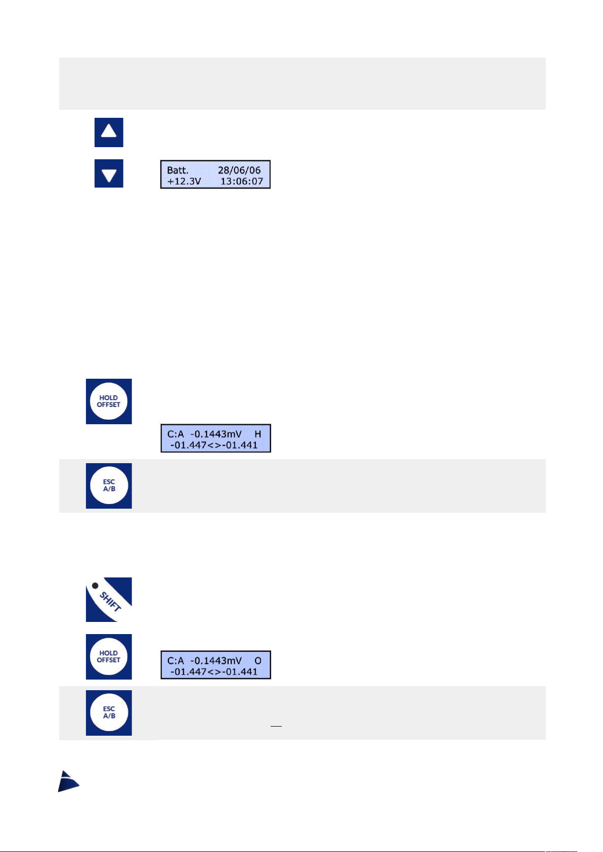
By using the
UP
and
DOWN
arrows, you can switch between showing
the instrument reading or the battery status.
During the reading phase the following operations are possible:
HOLD
- stop the reading on a desired data
OFFSET
- remove a desired offset from the reading
MEM
- data storage
HOLD
By pressing
HOLD/OFFSET
during the acquisition phase, DATAVIEW will
enter the HOLD function, which allow you to stop the reading and keep
the displayed data fixed.
The letter H will flash on the top right of the display.
By pressing
ESC
, you can exit the HOLD function.
OFFSET
By pressing
SHIFT
first and then
HOLD/OFFSET
during the acquisition
phase, DATAVIEW will enter the OFFSET function, which allow you to
deduct this value just measured (TARE) from the reading.
The letter O will flash on the top right of the display.
To exit and return the read value to the previous one, press
SHIFT
and
GAIN/OFFSET
again or press
ESC
.

7
MEM
By pressing
MEM/SETUP
, you can store the displayed data. There are
9999 memory spots.
The display will show a data saving screen.
By using the
LEFT
and
RIGHT
arrows, you can choose which memory
spot you want to save the displayed data. The spot will move one unit at
a time.
By pressing
SHIFT
first and then using
LEFT
and
RIGHT
arrows, the spot
will move ten by ten.
Then press
ENTER
to confirm the memory spot and save the data.
By using the
UP
and
DOWN
arrows, it is possible to view the other
informations relating to the memory spot (channel, reading, min, max).
Once you have chosen the desired memory spot, you can enter a
4-character code (at bottom left of the display) to remember more easily
the association of the instrument with the stored data.
With the
LEFT
and
RIGHT
arrows, you can move between the 4 spots,
while with the
UP
and
DOWN
arrows you choose the character on each
spot.
To confirm, press
ENTER
.
To go back in the menu press
ESC
.
To review the stored data, just turn on the DATAVIEW and press
MEM/SETUP
.
SCALE
By pressing
SHIFT
and then
GAIN/SCALE
, you can choose the
measurement scale you want to use.
There are up to 6 scales available*, which allow you to connect every SIM
instruments.
*In the DW-BSE model, there is only 1 scale available and it must be
specified when ordering

8
By using the
UP
and
DOWN
arrows, you can select the desired SCALE.
To confirm the selection, press
ENTER
.
GAIN
By pressing
GAIN/SCALE
, you can choose which GAIN you want to use.
For each measurement scale* (analog input type), there are 8 selectable
GAINS (analog signal scaling). The first cannot be modified and it
corresponds to the chosen scale. The others can be modified in the
SETUP function or with the DATAVIEW software.
By using the
UP
and
DOWN
arrows, you can select the desired GAIN.
To confirm the selection, press
ENTER
.
SETUP
By pressing
SHIFT
first and then
MEM/SETUP
, you can enter the control
unit setting mode, where you can change date and time and the
conversion values of the GAINS.
By using the arrows, you can select the SCALE first and then the GAIN.
Within each GAIN there are the following settings to be set:
• Decimal point
• Conversion value for start of scale
• Conversion value for the full scale
• Unit of measure (4 characters)
• Associate a P key (P1, P2, P3, P4) in order to have immediate
programming for the most used instruments.
P1/P2 – P3/P4
Once all the data have been set, you can easily recall the programmed P
Keys.
By pressing
P1/P2
or
P3/P4
, you can recall respectively P1 or P3.
By pressing
SHIFT
first and then
P1/P2
or
P3/P4
, you can recall
respectively P2 or P4.

9
Connections
4
POWER connector
PIN 1 = + Supply 12-13,8 Vcc External Battery
PIN 2 = - Supply
PIN 3 = N.C.
PIN 4 = N.C.
SIGNAL connector
PIN 1 = INPUT + Channel A
PIN 2 = INPUT - Channel A
PIN 3 = INPUT + Channel B
PIN 4 = INPUT - Channel B
PIN 5 = Ground
PIN 6 = +5Vcc
PIN 7 = +12Vcc
10
Software
5
DATAVIEW software is used to setup and to download the data stored in the readout unit.
DATAVIEW software can be supplied on a USB key or it can be downloaded directly from
SIM STRUMENTI website, in the downloads section:
https://www.simstrumenti.com/downloads/software/
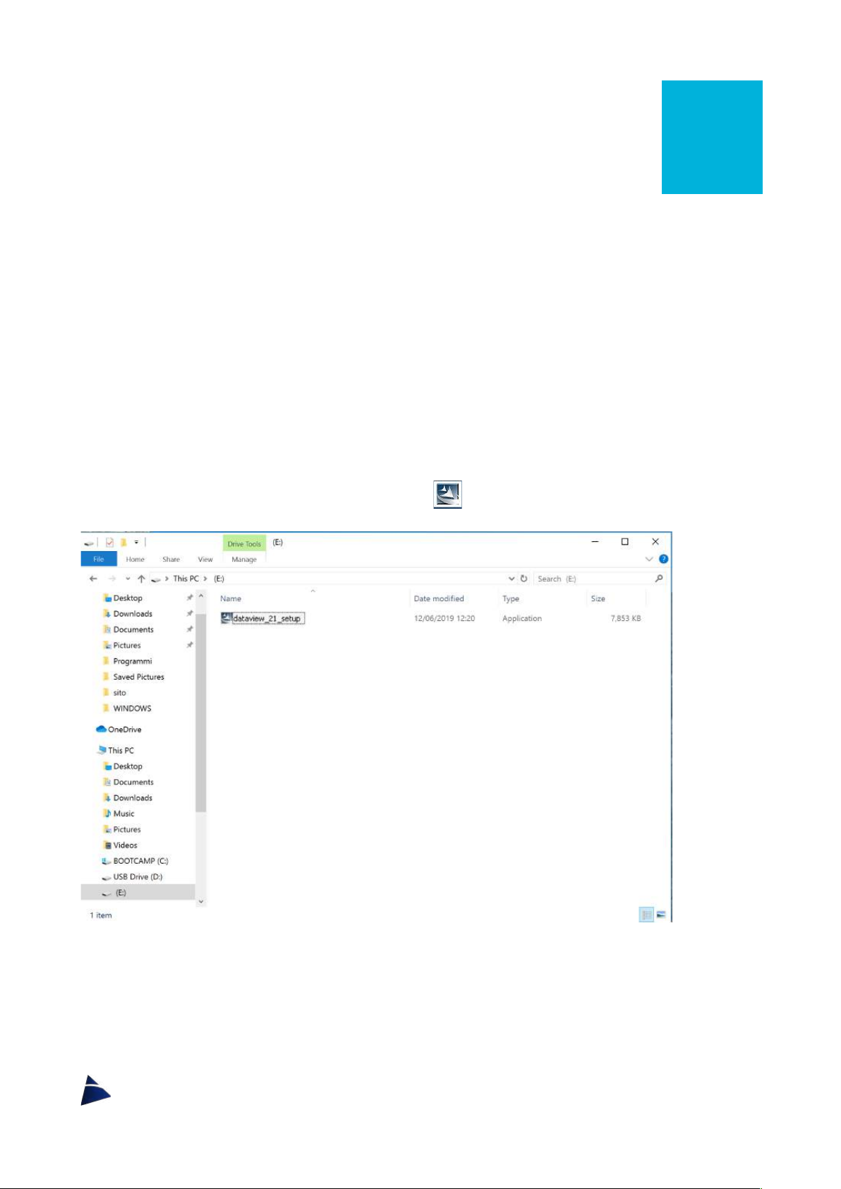
Installation
To start the installation, click twice on the icon
dataview_xxx_setup
(Img.1).
Img. 1
A communication window (Img.2) will open, and here it will be possible to select the
language for the installation. Therefore, select the desired language among the available
options and then click
OK
to move on.

11
Img. 2
An installation window will open and there will be the need to wait that the Preparing to
install will be completed (Img.3).
Img. 3
On the following window (Img.4), click on
Next
to proceed with the installation, or on
Cancel
to interrupt it.
Img. 4
12
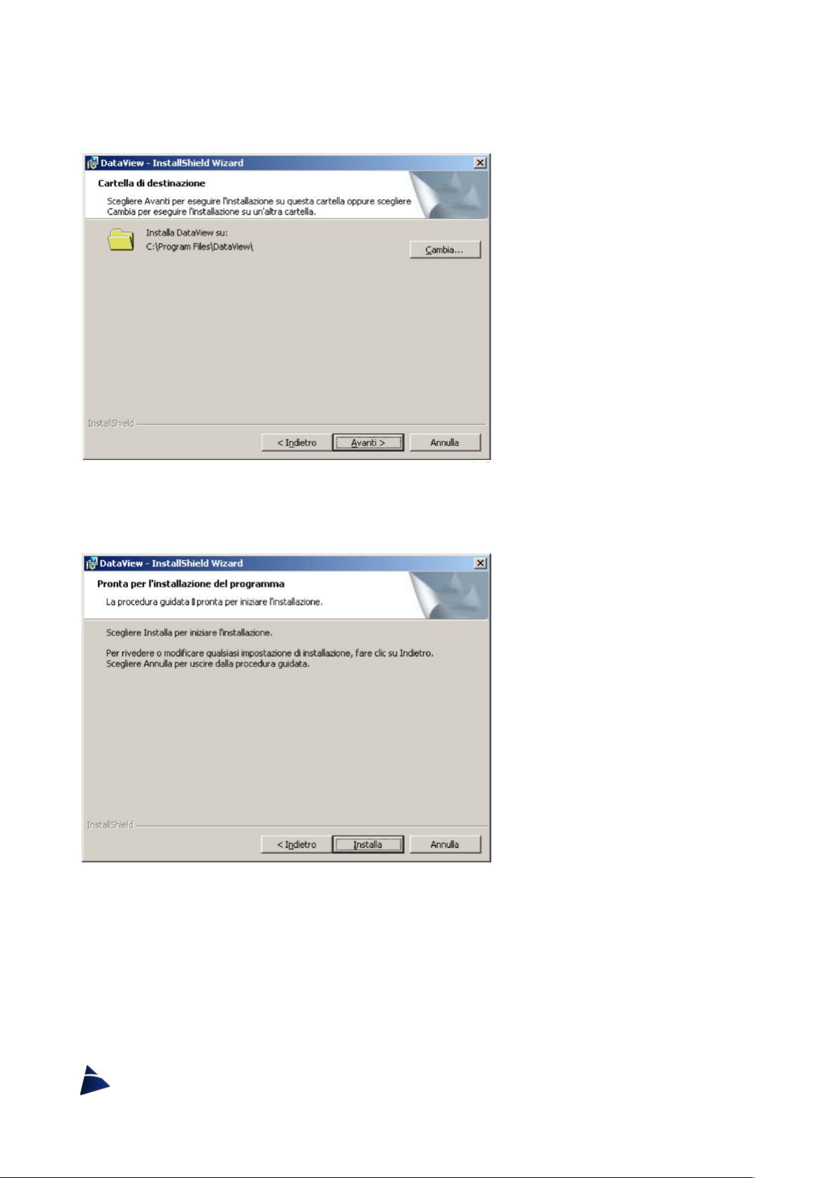
By continuing with the installation (Img.5) in which it will be possible to change the
destination folder for the DATAVIEW software. To keep going, click on
Next
.
Img. 5
On the next window (Img.6) click on
Install
to proceed with the actual installation.
Img. 6
During the installation, a communication window (Img.7) will appear, in which it will be
possible to undo the installation by clicking on
Cancel
.

13
Img. 7
At the end, another window (Img.8) will show up to confirm DATAVIEW software has been
successfully installed. Click now on
FINISH
.
Img. 8

14
Uninstall
In the case there will be the need to uninstall DATAVIEW software, there is a special
program called UNINSTALL DATAVIEW x.x.
To uninstall, proceed in the following way:
START PROGRAMS
DATAVIEW
UNINSTALL DATAVIEW x.x
For the uninstall procedure of the software, a window will come up where there will be the
need to confirm the uninstall process (Img.9). Click on
YES
to do so.
Img. 9
When the next window (Img.10) will appear, wait for the cancellation of all the software files.
If you want to stop the uninstall process, click on
Cancel
.
Img. 10

15
Start
To start the DATAVIEW software, proceed in the following way:
START PROGRAMS
DATAVIEW
DATAVIEW x.x
Img. 11
During the loading of the program, it will be visible the boot screen (Img.11) and after it will
appear a window (Img.12) to choose the device with which you want to connect.
Select the device to connect with and click
OK
.
Img. 12
After clicking on OK, the main screen will open (Img.13, 14).

16
Img. 13
Img. 14
17
Main screen sections
DATAVIEW
DATAFLOW
Menu bar
Menu bar
Data grids (one tab for each scale)
Setting tabs
Buttons to set and receive data from the unit
Buttons to set and receive data from the unit
Menu bar
DATAVIEW
DATAFLOW
• Data
o Transfer
• Help
o Help
o About
• Exit
o Exit
• Angle
o Degrees
o Radians
• Help
o Help
o About
• Exit
o Exit
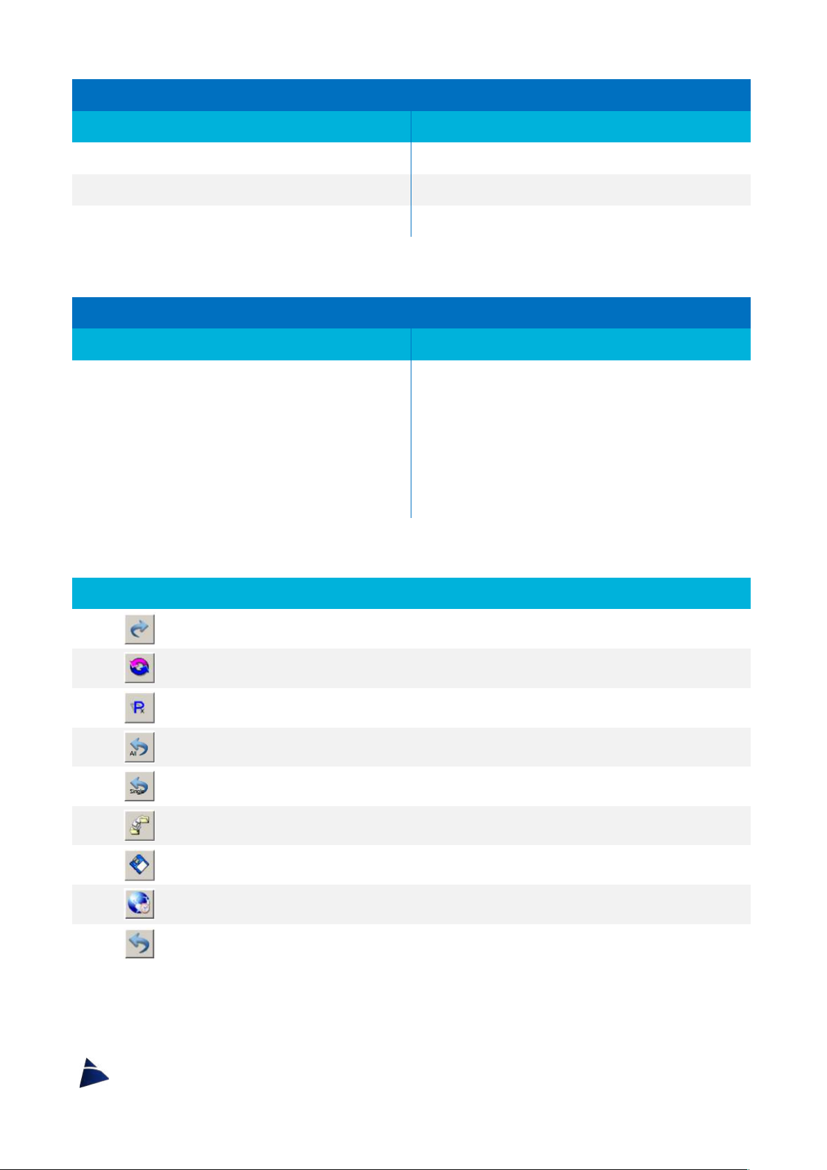
Buttons
For getting the configuration from the readout unit.
Loading the default data into the grids.
Opens the window for setting the programmable keypads P1, P2, P3, P4.
Sets the readout unit with the data inserted in the grids.
Sets the readout unit with the data inserted in the selected grid.
Opens a configuration file.
Saves a configuration file.
Insert in the relative text boxes the system date and time.
Sets the date and time in the readout unit.

18
Communication Port
In the right lower part of the screen, there is a frame where it is possible, if needed, to
change the communication port.
Date & Time
By clicking on the button , the date and time of the system will appear in the text boxes.
To change the date and time of the device, it is possible to insert the data manually or using
the time of the pc. Click the button to send the data into the device.
Configuration
This section is dedicated to set the parameters stored in the device.
Getting
By pressing the button it will activate the procedure of receiving all data stored in the
DATAVIEW/DATAFLOW.
In case of a connection to a DATAVIEW, a communication window will appear (Img.15),
asking if you want to continue receiving the stored data. Click
Yes
to confirm.
Img. 15

19
A window will appear (Img.16, 17), which will display the progress of the communication.
DATAVIEW
DATAFLOW
Img. 16
Img. 17
Once the procedure is finished, it will be possible to change the data.
In order to change the data, the value inside the box must be cancelled first, by pressing the
BACKSPACE
button on the keyboard.
!
DATAVIEW
The Gain 1 in each scale is displayed with a grey background because it has default
values that cannot be changed.
Editable Data in DATAVIEW
Decimal Point
Shows the number of digits after the point.
It is possible to insert a value between 0 and 5.
Start Scale
Displays the conversion value for the beginning of the measured scale.
It is possible to insert a value between –99999 and +99999.
End Scale
Displays the conversion value for the end of the measured scale.
It is possible to insert a value between –99999 and +99999.
Unit
Shows the unit of measure.
It is possible to insert up to 4 alphanumeric digits.
Label
Show the label connected to the gain for an easy way of recognition.
It is possible to insert up to 4 alphanumeric digits.
Editable Data in DATAFLOW
A/D Conversion
Label
Show the label connected to the gain for an easy way of recognition.
It is possible to insert up to 4 alphanumeric digits.
Start Scale
Displays the conversion value for the beginning of the measured scale.
It is possible to insert a value between –99999 and +99999.
End Scale
Displays the conversion value for the end of the measured scale.
It is possible to insert a value between –99999 and +99999.
Table of contents
Other SIM Marine Equipment manuals

Popular Marine Equipment manuals by other brands

Quick
Quick GP2 Genius 1500 Series Manual of installation and use

Protekt
Protekt AT 183 instruction manual

Fusion
Fusion MS-RA210 Quick start manual

Daikin
Daikin LXE10E-A37 Service manual and parts list

Lowrance
Lowrance LBS-1 installation instructions

Sealite
Sealite Atlantic-2600 Installation & service manual

Seastar Solutions
Seastar Solutions HA5456 installation instructions

PME MARE
PME MARE CLIK EASY user manual

Furuno
Furuno FELCOM19 Inmarsat Mini-C MES Operator's manual

Raymarine
Raymarine SmartPilot ST7002 operating guide

CORRECT CRAFT
CORRECT CRAFT LINC 3.0 owner's manual

ALBIN PUMP
ALBIN PUMP Marine Defroster 9 kW Instructions for use


