ISIC DuraMON10-27 S-Line Series Assembly instructions

User Reference Manual –DuraMON10-27 S-Line Series
PN: 09330-000 Rev A Page 1
DuraMON10-27
S-Line Series
DuraMON10.1 S-Line
DuraMON15.6 S-Line
User Reference Manual

User Reference Manual –DuraMON10-27 S-Line Series
PN: 09330-000 Rev A Page 2
Disclaimer
ISIC A/S makes no representation or warranties with respect to the contents or use of this manual,
and specifically disclaims any express or implied warranties of merchantability or fitness for any
particular purpose. Further, ISIC A/S reserves the right to revise this publication and to make
changes to its content at any time, without obligation to notify any person or entity of such revisions
or changes.
Image sticking: If the monitor is operated with static images (logo’s etc.) it will inevitably lead to
images sticking on the display. Image sticking can be reduced by regular operate the monitor with
moving pictures that is designed for the purpose.
FCC Warning
Computing devices and peripherals generate and radiate radio frequency energy, and if not
installed and used in accordance with the instructions advised by ISIC A/S, it may cause
interference to radio communication.
The DuraMON10-27 S-Line series, manufactured by ISIC A/S, is designed to comply with the
emerging generic EEC standards that cover applications in maritime environment.
Classification
The monitor is classified as “protected from the weather” according to IEC 60945 ed.4 (former class
b).
Approvals
Approval according to IEC 60945: Ed. 4 2002/COR1:2008 and IACS E10 Rev. 7 Oct. 2018, Maritime
navigation and radio communication equipment and systems –General requirements.
ISIC A/S is complying with the WEEE directive within the European Union, stating that electronic and
electric products must be collected separately.
Products are marked according to the directive.
Copyright 2021 ISIC A/S
ISIC A/S
Edwin Rahrs Vej 54
DK-8220 Brabrand
Denmark
Phone: +45 70 20 70 77
Web: http://www.isic-systems.com
Mail: isic@isic-systems.com

User Reference Manual –DuraMON10-27 S-Line Series
PN: 09330-000 Rev A Page 3
Table of Contents
1FEATURES...............................................................................................................................................................4
2GENERAL CONSIDERATIONS AT INSTALLATION AND OPERATION...................................................5
3INSTALLATION......................................................................................................................................................5
3.1 MECHANICAL OUTLINE .......................................................................................................................................5
3.2 DESKTOP/CEILING MOUNTING KIT WITH TILT ......................................................................................................5
3.3 CONSOLE MOUNTING KIT (SEALING IP44):..........................................................................................................5
3.4 COMPASS SAFE DISTANCE....................................................................................................................................5
3.5 POWER CONSUMPTION ........................................................................................................................................6
3.6 INRUSH CURRENT ................................................................................................................................................6
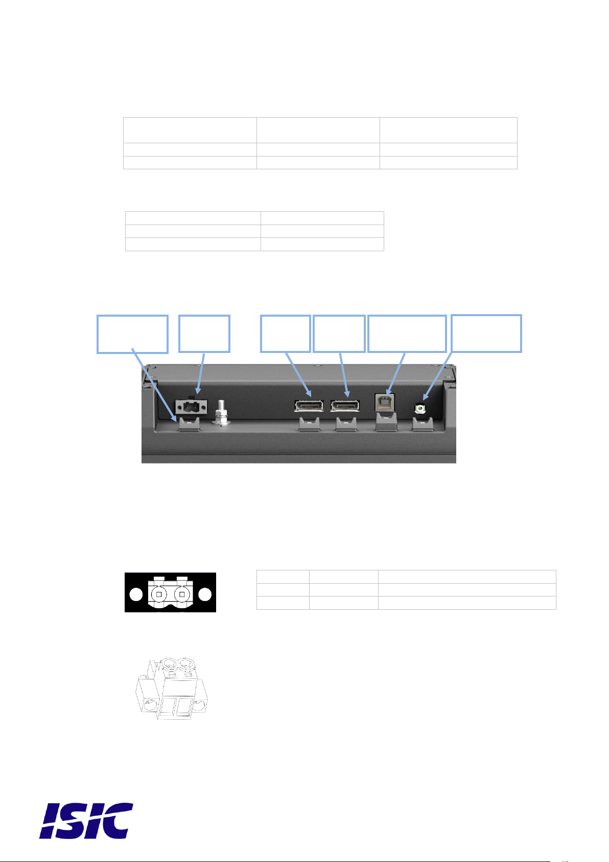
4DURAMON10-27 S-LINE CONNECTIONS.........................................................................................................6
4.1 24VDC (18-36VDC) SUPPLY VOLTAGE .............................................................................................................6
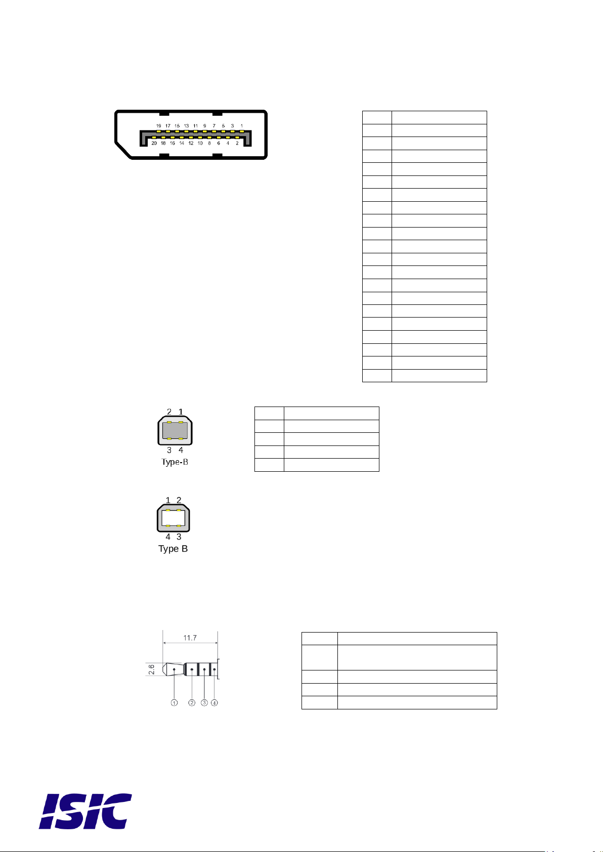
4.2 DISPLAYPORT 1.2 (DP) RECEPTACLE ..................................................................................................................7
4.3 USB TYPE BRECEPTACLE...................................................................................................................................7
4.4 2.5 MM JACK (RESERVED FOR FUTURE USE)...........................................................................................................7
5DURAMON10-27 S-LINE STATUS LED..............................................................................................................8
6TECHNICAL SPECIFICATIONS DURAMON10-27 S-LINE............................................................................9
7DURAMON S-LINE SERIES COMMUNICATION INTERFACE....................................................................9
7.1 VIRTUAL COM PORT ..........................................................................................................................................9
7.2 DDC/CI VCP COMMAND....................................................................................................................................9
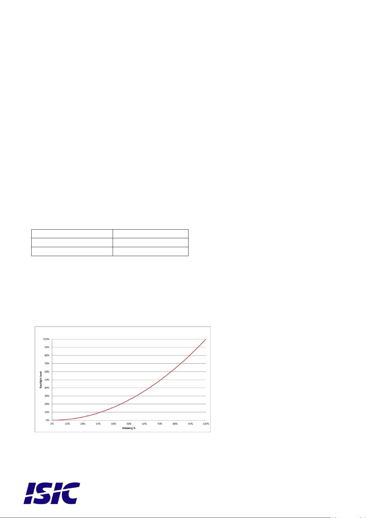
8DIMMING CURVE..................................................................................................................................................9
9USB TOUCH...........................................................................................................................................................10
10 OSD......................................................................................................................................................................10
10.1 STANDBY...........................................................................................................................................................10
11 TROUBLESHOOTING.....................................................................................................................................10
12 SERVICING THE UNIT ...................................................................................................................................10
13 TERMS, ACRONYMS AND ABBREVIATIONS...........................................................................................10
14 ISIC INFO / SUPPORT .....................................................................................................................................11
15 REVISION HISTORY .......................................................................................................................................12
16 APPENDIX A: PIXEL POLICY.......................................................................................................................13

User Reference Manual –DuraMON10-27 S-Line Series
PN: 09330-000 Rev A Page 4
1Features
Congratulations on your product purchase of DuraMON10-27 S-Line series.
This short form manual is designed to get you started working with your new DuraMON10-27 S-Line.
DuraMON10-27 S-Line series of monitors are all made as rugged monitors especially designed for
the demanding operating conditions at sea.
The DuraMON10-27 S-Line series are tested for full compliance to marine-standards IACS E10 and
IEC 60945.
The monitor comes with excellent brightness and contrast levels that, together with wide viewing
angles, ensure a good readability thus making it very eye-friendly. For the best picture quality,
always use a double shielded cable with ferrites, like the one supplied with the monitor.
18-36VDC Marine isolated supply
2 x Display Port
Feature control support for DDC/CI VCP commands via DisplayPort interface and USB
interface(Virtual COM Port)
Dimming control (1cd to 100%)
Anti-Reflective coated cover glass
IP65 protected front, mounted in sealed console.
USB Touch (Optional)

User Reference Manual –DuraMON10-27 S-Line Series
PN: 09330-000 Rev A Page 5
2General considerations at Installation and
Operation
DuraMON10-27 S-Line series are designed to work at conditions according to IEC 60945. However,
keeping the temperature and vibration level at a minimum will extend the lifetime of the product.
ISIC recommend operating this product at normal room temperature (20-25°C), with the lowest
level of vibration and humidity.
Installation of the DuraMON10-27 S-Line Series
To obtain best possible operating conditions, please note the following precautions.
-Cooling.
When mounting DuraMON10-27 S-Line series in cabinet/console, please ensure that air
can flow freely around the product cabinet, to avoid any unnecessary rise in
temperature. If it is not possible to have an adequate natural airflow, please ensure
forced airflow inside the console.
-Sunlight
If the unit can be exposed to direct sunlight, there is a potential risk that the unit can be
overheated. Please take measures to prevent direct sunlight. Do also consider forced
cooling on the back of the unit.
3Installation
Please also refer to Mechanical Outline for installation
3.1 Mechanical Outline
DuraMON 10.1 S-Line: 09311-000
DuraMON 15.6 S-Line: 09316-000
3.2 Desktop/Ceiling mounting kit with tilt
DuraMON 10.1 S-Line: 09313-000
DuraMON 15.6 S-Line: 09314-000
3.3 Console mounting kit (Sealing IP44):
DuraMON 10.1 S-Line: 09353-000
DuraMON 15.6 S-Line: 09354-000
3.4 Compass safe distance
Test object / condition
Minimum Compass
safe distance [cm]
(5.4°/H deviation or a
horizontal magnetic
flux of 0.094µT)
Minimum Compass safe
distance [cm]
(18°/H deviation or a
horizontal magnetic flux
of 0.313µT)
DuraMON 10.1 S-Line
95
60
DuraMON 15.6 S-Line
110
70

User Reference Manual –DuraMON10-27 S-Line Series
PN: 09330-000 Rev A Page 6
3.5 Power Consumption
Test object / condition
Ptyp [W]
Pmax [W]
DuraMON 10.1 S-Line
9.1
12
DuraMON 15.6 S-Line
17.5
21.4
3.6 Inrush current
Test object / condition
Current[A] @ 24VDC
DuraMON 10.1 S-Line
4
DuraMON 15.6 S-Line
5
4DuraMON10-27 S-Line connections
4.1 24VDC (18-36VDC) Supply Voltage
24 VDC: Nominal input voltage. Galvanic marine isolated with reverse polarity protection.
18-36VDC: Operating voltage range.
Mating part: Weidmüller BLZP5.08HC/02/180F
Tool: 0.6x3.5mm slotted (flat headed) screwdriver
Terminal
Connection
Wire compliance
1
0VDC
Multicore AWG16-12 (1-4 mm2)
2
24VDC
Multicore AWG16-12 (1-4 mm2)
2.5 mm Jack
(Aux)
DP 2
DP 1
USB Type B
(Hub)
24VDC
1 2
Support for
cable straps

User Reference Manual –DuraMON10-27 S-Line Series
PN: 09330-000 Rev A Page 7
4.2 DisplayPort 1.2 (DP) receptacle
Mating part: Male full size DisplayPort connector
with mechanical latch.
Note! Only use DisplayPort cables with pin 20 unconnected
4.3 USB Type B receptacle
Mating part: Plug USB type B
4.4 2.5 mm jack (reserved for future use)
Mating part: 2.5 mm Jack for half duplex RS-485
Pin
Description
1
ML_Lane 0 (p)
2
GND
3
ML_Lane 0 (n)
4
ML_Lane 1 (p)
5
GND
6
ML_Lane 1 (n)
7
ML_Lane 2 (p)
8
GND
9
ML_Lane 2 (n)
10
ML_Lane 3 (p)
11
GND
12
ML_Lane 3 (n)
13
CONFIG1
14
CONFIG 2
15
AUX CH (p)
16
GND
17
AUX CH (n)
18
Hot plug
19
Return
20
DP_PWR
Pin
Description
1
VBUS (+5V)
2
Data-
3
Data+
4
GND
Pin
Description
1
5VDC (Only for ISIC
applications)
2
RS-485 A
3
RS-485 B
4
GND

User Reference Manual –DuraMON10-27 S-Line Series
PN: 09330-000 Rev A Page 8
5DuraMON10-27 S-Line status LED
The LED is not marked on the front and is only visible when lit.
Status LED indicating color:
No light + LCD picture: OK - Normal operation
No light + LCD no picture: No power
Orange: Standby (brightness follows the LCD backlight setting)

User Reference Manual –DuraMON10-27 S-Line Series
PN: 09330-000 Rev A Page 9
6Technical specifications DuraMON10-27 S-Line
Please refer to datasheet for the purchased variant
DuraMON 10.1 S-Line: 09328-000
DuraMON 15.6 S-Line: 09329-000
7DuraMON S-Line Series Communication
interface
DuraMON S-Line series support 2 type of communication protocols
DDC/CI VCP command via DisplayPort
Virtual Serial Communication via USB interface.
7.1 Virtual COM Port
Please refer to Serial Communication Protocol 04924-002
The type of the product can be queried by sending the ‘TYP’ command to the Virtual COM Port.
Monitor
Response from monitor
DuraMON 10.1 S-Line
DM101
DuraMON 15.6 S-Line
DM156
7.2 DDC/CI VCP Command
Please refer to DDC/CI VCP Command protocol 09370-002.
8Dimming curve
The dimming curve is 12-bit squared from 1 cd to maximum brightness for display.

User Reference Manual –DuraMON10-27 S-Line Series
PN: 09330-000 Rev A Page 10
9USB Touch
Monitors with optional multi-PCAP touch sensor comply to Windows 8 (or newer) standard USB HID
drivers. Linux operating systems might come with the HID driver as part of the Linux kernel,
compatibility is not guaranteed.
10 OSD
10.1 Standby
When no input signal is detected the screen will display “No signal” for 15 sec and enter standby
mode.
11 Troubleshooting
Problem
Cause
Solutions
No picture on display
Backlight level set to minimum
Increase backlight
No picture on display
Monitor turned off
Turn on the monitor
No picture on display
No input signal present
Apply signal
No picture on display
No power cord connected
Apply power
The unit will not turn on.
Unknown
Please do not try to open the
unit. Send it to ISIC A/S for
repair.
12 Servicing the unit
In case that the unit still fails after following the troubleshooting send the unit to ISIC for repair. There
are no user serviceable parts inside and to ensure ECDIS compliance the monitor has to be
recalibrated at ISIC.
13 Terms, Acronyms and abbreviations
OSD:
On Screen Display
No signal

User Reference Manual –DuraMON10-27 S-Line Series
PN: 09330-000 Rev A Page 11
14 ISIC info / Support
In case you have inquiries or problems with your DuraMON10-27 S-Line, you have a number of
possibilities to get support.
Company name: ISIC A/S
Head office: Edwin Rahrs Vej 54
DK –8220 Brabrand
Denmark
Shipping address: Holmstrupgaardvej 5
DK-8220 Brabrand
Denmark
Telephone: +45 70 20 70 77
Mail: isic@isic-systems.com
www: www.isic-systems.com
VAT number: DK 16 70 45 39
Bank Address: Handelsbanken A/S
Havneholmen 29
DK-1561 København V
Denmark
Bank Code: 0892
IBAN DKK: DK53 0892 0001 0159 69
IBAN EUR: DK48 0892 0003 0026 19
IBAN USD: DK26 0892 0003 0026 27
SWIFT: HANDDKKK
Contacts:
RFQ’s: By mail to sales@isic-systems.com
Orders: By mail to orders@isic-systems.com
Support: Via homepage www.isic-systems.com under aftersales
By mail to service@isic-systems.com
During office-hours (Mo-Fr: CET 0800 - 1500) at +45 70 20 70 77
Service: Before shipment for service Request Return Material Authorization number at
homepage https://isic-systems.com/after-sales/tech-support-rma/
By mail to service@isic-systems.com

User Reference Manual –DuraMON10-27 S-Line Series
PN: 09330-000 Rev A Page 12
15 Revision history
Rev 0
April 2021
Preliminary
Rev A
June 2021
First release

User Reference Manual –DuraMON10-27 S-Line Series
PN: 09330-000 Rev A Page 13
16 Appendix A: Pixel policy
ISO 9241-307:2008 guidelines for LCD pixel defects
Introduction
TFT displays consist of a set number of pixels. Each pixel consists of 3 sub-pixels also called dots (one
red, one blue and one green). Every sub-pixel is addressed by its own transistor. As a result, the
manufacturing of glass substrate is very complex.
Due to the nature of this manufacturing process, occasional defects can occur. Pixel defects or
failures cannot be fixed or repaired and may occur at any stage during the service life of the TFT
display.
To regulate the acceptability of defects and protect the end user, ISIC A/S complies with the ISO
9241-307:2008 standard. This standard recommends how many defects are considered acceptable
in a display, before it should be replaced within the terms of the warranty.
Monitor classification
ISO 9241-307:2008
Allowed defects per type per million pixels
Defect classes
Pixel defects
Cluster defect
Type 1
Type 2
Type 3 total
(2xN3a + N3b)
Type 1
Type 2
Type 3
Class: 0
0
0
0
0
0
0
Class: I
1
1
5
0
0
0
Class: II
2
2
10
0
0
1
Class: III
5
15
100
0
0
5
ISIC TFT monitors comply with ISO 9241-307:2008 Class II.
Special agreements about other classifications can be made between ISIC A/S and the customer.
Measurement method/monitoring conditions for pixel defects
In compliance with the ISO-9241-307:2008 standard, the following conditions are observed:
Final check for pixel fault undertaken right after burn-in, i.e. with pre-heating of the display.
Surrounding temperature 25ºC ± 5ºC
Relative air humidity 40–70%
Pixel definition
Every pixel consists of three sub-pixels/dots (red, blue, green).
Every sub-pixel has its own transistor.
The three sub-pixels/dots must be considered as one unit.

User Reference Manual –DuraMON10-27 S-Line Series
PN: 09330-000 Rev A Page 14
Pixel
Pixel defect type 1 Pixel constantly lit Pixel defect type 2 Pixel constantly dark
Pixel defect type 3a Pixel defect type 3b
Sub-pixel/dot (red, blue, green) constantly lit Sub-pixel/dot (red, blue, green) constantly
dark
Cluster
A cluster consists of 5 x 5 pixels.
Cluster pixel defect type 1 Cluster pixel defect type 2
Pixels in a cluster area constantly lit Pixels in a cluster area constantly dark
Cluster pixel defect type 3a Cluster pixel defect type 3b
Sub-pixels/dots in a cluster area constantly lit Sub-pixels/dots in a cluster area constantly
dark

User Reference Manual –DuraMON10-27 S-Line Series
PN: 09330-000 Rev A Page 15
Pixel faults accepted by ISIC A/S
The maximum number of pixel faults that is considered acceptable at different screen resolutions is
shown in the table below. This is the native resolution and not the resolution as adjusted by user.
Class II
Allowable number of pixel faults in monitor applications
Screen
type
Native
resolution
Number of
pixels
Pixel defect
type 1
Pixel defect
type 2
Pixel defect
Type 3 total
(2xN3a + N3b)
Cluster
defect
type 1 and
2
Cluster
defect
type 3
WVGA
800x480
384,000
0
0
3
0
0
XGA
1024x768
768,432
1
1
7
0
0
WXGA
1280x800
1,024,000
2
2
10
0
1
SXGA
1280x1024
1,310,720
2
2
13
0
1
UXGA
1600x1200
1,920,000
3
3
19
0
1
FHD
1920x1080
2,073,600
4
4
20
0
2
WUXGA
1920x1200
2,304,000
4
4
23
0
2
This manual suits for next models
2
Table of contents
Other ISIC Marine Equipment manuals
Popular Marine Equipment manuals by other brands

Lowrance
Lowrance X-1550 Installating and operation manual

Vigilant
Vigilant 80DSB quick start guide

DIGITAL YACHT
DIGITAL YACHT AISnet Internet Base Station Installation & quick start guide

Sealite
Sealite TRIDENT-3000 Installation & service manual

Furuno
Furuno FMD3100 Operator's manual

iXBlue
iXBlue GAPS II quick start guide