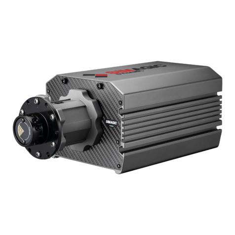
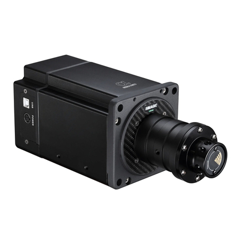
Simagic M10 Base User manual

Stepper Base M10
www.simagic.com

To get the most out of your Stepper Base M10, please read this manual before use. It contains
important health and safety information and should be retained for future reference.
TECHNICAL CHARACTERISTICS
Three CPUs are incharge of motor control, game effects, and USB
real-time communication respectively. They enable the whole system to
make force-feedback faster and more complete .Let driver feel the status
of the vehicle accurately.
The control frequency of force feedback is 40,000 times per second, not
missing every minute detail.
The resolution of encoder is 16384 per turn.it is more accurate and
smoother.
The newly designed three-phase hybrid stepping motor is smoother and
faster than the traditional stepping motor. The maximum torque can be
up to 10nm, which is enough to simulate the torque of most real cars.
Direct drive enables a more direct driving experience with the steering
wheel directly connected to the motor shaft, and with no belts or gears.
The real-time game data interaction has a frequency of 1000 Hz per
second.
It enjoys a new control software which has abundant functions and is
easy to adjust. One can adjust and have different steering feelings based
on his or her needs.
The new setting of the drift mode, and the perfect balance between the
strength and the speed of turning the steering wheel, bringing a
completely new drift experience.
There are a variety of peripheral expansions.

Stepper Base M10
3
INDEX
1. General ................................................................................................................ 5-6
2. Introduction ......................................................................................................... 7
3. Compatibility........................................................................................................ 7
4. Preparation .......................................................................................................... 8
4.1 Package contents ........................................................................................ 8
5. Assembly.............................................................................................................. 9-18
5.1 Plan your configuration .............................................................................. 9
5.2 Mounting the Podium Wheel Base DD1 using the
ClubSport Table Clamp V2................................................................................ 9
5.3 Hard-mounting the Podium Wheel Base DD1 ........................................... 10
5.4 Attaching a Steering Wheel ........................................................................ 11-13
5.5 Changing the Quick Release ...................................................................... 14-15
5.6 Connections ................................................................................................. 16-17
5.7 Drilling Template.......................................................................................... 18
6. Functions & Features.......................................................................................... 19-34
6.1 Firmware and driver update........................................................................ 19-28
6.2 Start-Up procedure ...................................................................................... 28-29
6.3 Tuning Menu................................................................................................. 29-32
6.4 OLED Display ............................................................................................... 33
6.5 Cooling system............................................................................................ 34
7. Electronic operation............................................................................................ 35-38
7.1 Hotkeys......................................................................................................... 35-38
8. Cleaning ............................................................................................................... 39
9. Troubleshooting .................................................................................................. 39-40
10. Serial number..................................................................................................... 41
11. Trademarks......................................................................................................... 41
12. End of Life Product Recycling ......................................................................... 42
13. FCC Compliance................................................................................................ 43
14. Warranty ............................................................................................................. 43-44

Stepper Base M10
The device must not be exposed to rain or humidity in order to avoid risk of fire and/or electric
shock.
• Operating room temperature: 59°F - 95°F
• The recommended operation time of the wheel with continuous force feedback activity is 1 hour.
• Excessive use may cause health risks. We recommend to take a break of 5 minutes every 20
minutes, and do not drive for more than 2 hours per day.
• Not intended for children under the age of 13 years old. Contains small pieces which pose a
choking hazard!
• Do not open the casing of the device.
• This device contains components that cannot be repaired by the user, opening will void the
warranty.
WARNING! Electrical Safety
• The Stepper Base M10 must be connected to an appropriate power source:
• Always connect the DC side of the power supply to the wheel base before connecting the
AC side of the power supply to your wall socket.
• Use only the power supply and power cord that came with your Stepper Base M10.
Replacements may only be issued from an authorised repair centre.
• Do not use non-standard power sources, such as generators or inverters, even if the voltage
and frequency appear acceptable. Only use AC power provided by a standard wall outlet.
• To avoid damage, do not expose your Stepper Base M10 to sources of heat.
• When connecting and / or disconnecting any steering wheel to / from Stepper Base M10
take care of the pins inside the Quick Release.
• Unplug the power cord of your Stepper Base M10 during storms or when unused for
long periods of time.
• If the Stepper Base M10 becomes damaged in any way, stop using it immediately and
contact Simagic Customer Support http://www.simagic.com
ATTENTION
Stepper Base M10 is fully usable out-of-box. We always recommend updating to the
latest firmware. See chapter ‘Firmware and driver update’ for more details. A PC is required to
update your firmware.
• All specifications in this document are subject to change. The Stepper Base M10 firmware
and/or PC driver may be updated to implement new features or general improvements.
• This product contains the all other Simagic steering wheels which might be mentioned in this
manual are not included within the Stepper Base M10 package and sold separately. You
can obtain them from the Simagic webshop: www.simagic.com
• This manual discusses assembly, connections, and functions related to Simagic steering wheels
and other additional devices. This is not a replacement manual for the other corresponding
products! Read the quick guides or user manuals for the other products as well!
• The warranty does not include defects that are due to commercial use of the product. See
chapter “Warranty” at the end of this user manual as well as the Terms & Conditions at
www.simagic.com for more details.
GENERAL NOTES
4

Stepper Base M10
5
Thank you for purchasing the Stepper Base M10. This product contains many advanced
technologies, including a custom outrunner servo motor, integrated electronics, and wireless
Quick Release system. Built from the ground up for sim racing, the motor delivers 10Nm peak
torque, with outstanding wheel speed and acceleration. Welcome to the Direct Drive Revolution.
The Stepper Base M10 is compatible with the PC.
IMPORTANT: Stepper Base M10 is fully usable out-of-box.
We always recommend updating to the latest firmware. A PC is required to update your firmware.

Stepper Base M10
6
PACKAGE CONTENTS
Stepper Base M10
Power supply unit
D1 QR Simagic
Power supply cable USB connection cable
ScrewMounting Brackets T-Nut

Stepper Base M10
7
ASSEMBLY
1
2
1
2
3
3
4
4

Stepper Base M10
8
SETTING
SIMAGIC FFB ENGINE
MECHANICAL
+
WHEEL SPEED
TOTAL FORCE
OVERALL FILTER
WHEEL SPRING
WHEEL DAMPER
WHEEL FRICTION
GAME SPRING
GAME DAMPER
GAME INERTIA
GAME FRICTION
GAME FORCE
MECHANICAL FORCE: To enrich the handle of the game,
which works while whether the game is played or not.
TOTAL FORCE: To adjust the output range of the Force engine.
The positive or negative signs represent the direction of the
Force.
OVERALL FILTER: To adjust the smoothness of the output of
force engine. The higher the value, the smoother the output, the
lower the resonance frequency, and the less the details.
WHEEL SPEED:To adjust the highest speed of the wheel. The
value on screen represents the highest speed. SIMAGIC
algorithm does not intervene if the speed is below this value;
Otherwise the algorithm will limit the speed to set value.
WHEEL SPRING:To adjust the central spring of the wheel. The
larger the offset from the center, the greater the spring.
WHEEL DAMPER:To adjust the mechanical damper of the
wheel. The damper force hinders the wheel rotation. Damper
force= wheel speed * mechanical damper coefficient.
WHEEL FRICTION:To adjust the mechanical friction of the
wheel. The direction of friction is opposite to that of wheel
rotation. The value of friction can be adjusted by friction
coefficient.
The force engine of SIMAGIC is the combination of mechanical force and game force.
SPRING FORCE
RIGHT LIMITLEFT LIMIT CENTER
DAMPER FORCE
SPEED OF WHEEL
FRICTION FORCE
SPEED OF WHEEL

Stepper Base M10
9
SETTING
SIMAGIC supports six types of game force, and game may not use all types. At the beginning
of the game, the type that is chosen will turn red. Users can adjust the type of game force.
The default value of game force is 100, which is the original output of the game. Users can get
a good handle by adjusting the mechanical setting coefficient.
Constant force represents turning force in most games. Period force represents
detailed strength of collision and road condition in the game, etc.
WHEEL CENTER CALIBRATION
Rotate the wheel to center manually, and then
press the button CENTER
Two ways of changing the parameter in the
setting:
1.Pull the slider to change the parameter
2.Input the parameter through keyboards, and
then press “enter” to fuction
Upload parameter s from base to RaceManager.normally RaceManager will upload parameters
autoly when it is opened or base is connected.
To save parameters to base interal memorizer and remember these parameters even poweroff.
To save parameters to a “ini” file,user can save different setting for different game.and these
setting can be loaded by pull-down menu next to “save as”.

Stepper Base M10
10
CALIBRATION
WHEEL CENTER CALIBRATION
All peripherals from simagic will be linked to base by can bus.here show all 6 axises and 64
buttons. That will be enough for most of all games.

Stepper Base M10
11
SETTING
MOTOR SPEED:
SIMAGIC have 5 scales of motor speed to set different feeling of motor.you can see it represent
suspension hardness of car.
GAME MODEL:
Reserved
LANGUAGE:
To set language of Race Manager.
SYSTEM STATE:
To show the state of base. Errors will be show here. Normally errors can be clear by restart
base.
BASE OK - This led indicated connection with base
Other manuals for M10 Base
1
Table of contents
Other Simagic Switch manuals
