SIMALFA Primus User manual

SIMALFA®
Betriebsanleitung / Operating Instructions /
Instructions de Service / Instrucciones de Servicio /
Istruzione per l’uso / Instrukcja użytkowania /
Инструкция по эксплуатации
Spritzpistole / Spray Gun /
Pistolet de Pulvérisation / Pistola de Pulverización /
Pistola a spruzzo / Pistolet natryskowy
Пистолет-распылитель
SIMALFA Primus
REV. 02/19

Seite 4 - 19
Page 20 - 33
Page 34 - 47
Página 48 - 61
Pagina 62 - 75
Strona 76 - 89
Cтрани
ца 90 - 103
54
Inhaltsverzeichnis
EG-Konformitätserklärung 5
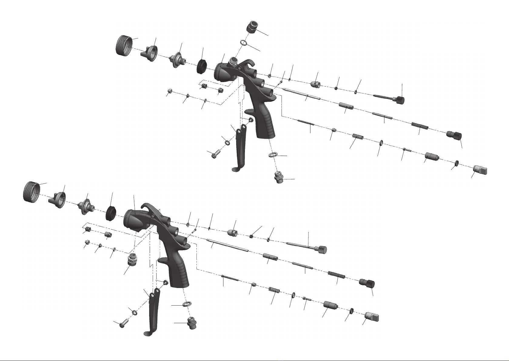
Explosionszeichnung 6
Ersatzteilliste 8
1 Allgemeines 10
1.1 Kennzeichnung der Modelle 10
1.2 Bestimmungsgemäße Verwendung 10
1.3 Sachwidrige Verwendung 10
2 Technische Beschreibung 11
3 Sicherheitshinweise 11
3.1 Kennzeichnung der Sicherheitshinweise 11
3.2 Allgemeine Sicherheitshinweise 11
4 Montage 12
4.1 Versorgungsleitungen anschließen 12
5 Bedienung 14
5.1 Inbetrieb- und Außerbetriebsetzen 14
6 Spritzbild verändern 14
6.1 Mängel eines Spritzbildes beheben 15
7 Fehlersuche und -beseitigung 16
8 Umrüstung und Instandsetzung 16
9 Reinigung und Wartung 17
9.1 Grundreinigung 17
10 Entsorgung 18
11 Technische Daten 19
EG/EU-Konformitätserklärung
Wir, der Gerätehersteller, erklären in alleiniger Verantwortung, dass das Produkt in der
untenstehenden Beschreibung den einschlägigen grundlegenden Sicherheits- und
Gesundheitsanforderungen entspricht. Bei einer nicht mit uns abgestimmten Änderung an dem
Gerät oder bei einer unsachgemäßen Verwendung verliert diese Erklärung ihre Gültigkeit.
Hersteller ALFA Klebstoffe AG
Vor Eiche 10
CH-8197 Rafz, Switzerland
Tel. +41(0) 43 433 30 30
Fax +41(0) 43 433 30 33
Email: [email protected]
www.simalfa.ch • www.alfa-klebstoffe.com
Alfa Adhesives, Inc.
15 Lincoln Street
Hawthorne, NJ 07506 USA
Telephone: 1 973.423.9266
Fax: 1 973.423.9264
Typenbezeichnung Handspritzpistolen SIMALFA Primus
Materialanschluss oben V 10 707
Materialanschluss unten V 10 708
Verwendungszweck Verarbeitung spritzbarer Materialien
Angewandte Normen und Richtlinien
EG-Maschinenrichtlinien 2006/42/EG
2014/34/EU (ATEX Richtlinien)
EN ISO 12100
DIN EN 1953 DIN EN 13463-1
DIN EN 1127-1 DIN EN 13463-5
Spezifikation im Sinne der Richtlinie 2014/34/EU
Kategorie 2 Gerätebezeichnung II 2 G c T 6
Bevollmächtigt mit der Zusammenstellung der technischen Unterlagen:
Thomas Simmler, ALFA Klebstoffe, Vor Eiche 10
CH-8197 Rafz, Switzerland
Besondere Hinweise :
Das Produkt ist zum Einbau in ein anderes Gerät bestimmt. Die Inbetriebnahme ist so lange
untersagt, bis die Konformität des Endproduktes mit der Richtlinie 2006/42/EG festgestellt ist.
Rafz, den 02. November 2016
Name: Thomas Simmler
Stellung im Betrieb: Geschäftsführer
Diese Erklärung ist keine Zusicherung von Eigenschaften im Sinne der Produkthaftung. Die Sicherheitshinweise
der Produktdokumentation sind zu beachten.
i.V.
76
Stand Februar 2019
SIMALFA Primus
Materialanschluss
(MA) unten
12
9
19
18
17
16
15
33
10
5
3
8
7
12
11
13
14
30
31
32
37
6
22
21
20
29
28
27
26
25
24
23
35
34
39 45
12
42
43
18
17
16
15
33
10
5
3
41
7
12
11
13
14
30
31
32
36
40
22
21
20
29
28
27
26
25
24
23
35
34
39
44
SIMALFA Primus
Materialanschluss
(MA) oben
45

98
Ersatzteilliste:
SIMALFA Primus
HVLP-Kleber
Materialanschluss unten
V 10 708
Pos. Bezeichnung Stck. Artikelnummer
30 Hebelschraube 1 V 10 301 09 000
31 Abzugshebel 1 V 10 707 11 000
32 Hebelschaftschraube 1 V 10 600 20 100
33 Begrenzungsstift 1 V 10 701 12 000
34 Farbring 1 V 10 701 13 300
35 Doppelnippel 1 V 00 101 01 000
37 Doppelnippel 1 V 00 101 04 pre
39 Federscheibe 1 V 10 701 11 100
45 Dichtung Luftmengenregulierung 1V 10 701 05 100
Ersatzteilliste: (abweichend von Simalfa Primus Materialanschluss unten)
SIMALFA Primus
HVLP-Kleber
Materialanschluss oben
V 10 707
Pos. Bezeichnung Stck. Artikelnummer
36 Adapter für Materialanschluss 1V 10 707 05 000
37 Doppelnippel entfällt
40 Pistolenkörper mit Buchsen 1V 10 707 03 000
41 Packungsschraube 1 V 10 701 02 000
42 Materialnadel 1 V 10 707 04 XX3
43 Regelschraube 1 V 10 701 06 000
44 Dichtring 1 V 00 130 00 065
* Bei Ersatzteil - Bestellung bitte entsprechende Größe angeben.
Wir empfehlen, alle fettgedruckten Teile (Verschleißteile) auf Lager zu halten.
Ersatzteilliste:
SIMALFA Primus
HVLP-Kleber
Materialanschluss unten
V 10 708
Pos. Bezeichnung Stck. Artikelnummer
1Luftkopfmutter kompl. 1V 10 707 01 000
2Luftkopf Alu (0,8 - 2,0 mm ø) 1V 01 101 86 100 *
Luftkopf Alu (2,5 - 3,0 mm ø) V 01 101 86 200 *
3 Materialdüse 1 V 10 707 02 XXX *
5 Luftverteilerring 1 V 10 701 14 100
6Pistolenkörper mit Buchsen 1V 10 708 01 000
7 Nadeldichtung kompl. 1 V 09 001 72 000
8 Packungsschraube 1 V 10 702 02 000
9Materialnadel 1 V 11 306 21 XX3
10 Mitnehmerbuchse 1 V 10 306 06 000
11 Konterschraube 1 V 10 701 03 000
12 Nadelfeder 1 V 10 701 40 000
13 Federkappe 1 V 10 701 04 000
14 Dichtkegel 1 V 11 700 11 200
15 Sicherungsscheibe 1 V 10 151 23 000
16 Führungsbuchse 1 V 10 600 05 200
17 Packung 1 V 09 101 02 020
18 Packungsschraube 1 V 10 600 29 100
19 Regelschraube 1 V 10 702 06 000
20 Ventilstopfbuchse 1 V 10 701 07 000
21 Nadeldichtung (Ventilschaftdichtung) 1 V 11 750 20 000
22 O-Ring 1 V 09 102 38 001
23 Ventilschaft kompl. 1V 10 701 08 300
24 Ventilkegel 1 V 10 701 08 000
25 Ventilfeder 1 V 10 701 41 000
26 Zylinderschraube 1 V 11 700 27 400
27 Buchse Luftmengenregulierung 1V 10 701 05 000
28 Dichtung Luftmengenregulierung 1V 10 701 09 000
29 Luftmengenregulierung 1 V 10 701 10 000
1110
1 Allgemeines
1.1 Kennzeichnung der Modelle
Modelle: Handspritzpistole SIMALFA Primus
Typ: Materialanschluss oben V 10 707
Materialanschluss unten V 10 708
Hersteller: ALFA Klebstoffe AG
Vor Eiche 10
CH-8197 Rafz, Switzerland
Tel.: +41(0) 43 433 30 30
Fax: +41(0) 43 433 30 33
www.simalfa.ch • www.alfa-klebstoffe.com
Alfa Adhesives, Inc.
15 Lincoln Street
Hawthorne, NJ 07506 USA
Telephone: 1 973.423.9266
Fax: 1 973.423.9264
1.2 Bestimmungsgemäße Verwendung
Die Handspritzpistole SIMALFA Primus dient ausschließlich der Verarbeitung von
Klebstoffen auf Wasserbasis, wie SIMALFA oder ALFA Dispersionen.
Sämtliche materialführenden Teile sind aus Edelstahl-rostfrei gefertigt.
Sind die Materialien, die Sie verspritzen wollen, hier nicht aufgeführt, wenden Sie
sich bitte an den Hersteller. Die spritzbaren Materialien dürfen lediglich auf
Werkstücke bzw. Gegenstände aufgetragen werden.
Die Temperatur des Spritzmaterials darf 43°C grundsätzlich nicht überschreiten.Die
bestimmungsgemäße Verwendung schließt auch ein, dass alle Hinweise und
Angaben der vorliegenden Betriebsanleitung gelesen, verstanden und beachtet wer-
den.
1.3 Sachwidrige Verwendung
Die Spritzpistole darf nicht anders verwendet werden, als es im Abschnitt 1.2
Bestimmungsgemäße Verwendung geschrieben steht.
Jede andere Verwendung ist sachwidrig.
Zur sachwidrigen Verwendung gehören z.B.:
• das Verspritzen von Materialien auf Personen und Tiere
• das Verspritzen von flüssigem Stickstoff.
2 Technische Beschreibung
Bei Betätigung des Abzughebels (Pos. 31) wird zuerst die Vorluft geöffnet und
danach die Materialnadel (Pos. 9) zurückgezogen. Hierdurch gelangt das
Spritzmaterial durch die Düse. Das Schließen erfolgt in umgekehrter Reihenfolge.
Die Materialdurchflussmenge ist abhängig vom Durchmesser der Düse und der
Einstellung des Materialdruckes am Freifluss-System (Höhe) Druckgefäß oder
Materialdruckregler. Zusätzlich lässt sich die Materialmenge durch Ein- bzw.
Ausschrauben der Stellschraube regeln. Zu weiteren Einstellmöglichkeiten siehe
6 Spritzbild verändern.
3 Sicherheitshinweise
3.1 Kennzeichnung der Sicherheitshinweise
Warnung
Das Piktogramm und die Dringlichkeitsstufe “Warnung“ kennzeichnen eine mög-
liche Gefahr für Personen.
Mögliche Folgen: schwere oder leichte Verletzungen.
Achtung
Das Piktogramm und die Dringlichkeitsstufe “Achtung“ kennzeichnen eine mög-
liche Gefahr für Sachwerte.
Mögliche Folgen: Beschädigung von Sachen.
Hinweis
Das Piktogramm und die Dringlichkeitsstufe “Hinweis“ kennzeichnen zusätzliche
Informationen für das sichere und effiziente Arbeiten mit der Spritzpistole.
3.2 Allgemeine Sicherheitshinweise
► Die einschlägigen Unfallverhütungsvorschriften sowie die sonstigen aner-
kannten sicherheitstechnischen und arbeitsmedizinischen Regeln sind einzu-
halten.
►Die Anwender müssen im gefahrlosen Umgang mit der Spritzpistole
entsprechend unterwiesen werden.
► Benutzen Sie die Spritzpistole nur in gut belüfteten Räumen. Im
Arbeitsbereich ist Feuer, offenes Licht und Rauchen verboten. Beim
Verspritzen leichtentzündlicher Materialien (z. B. Lacke, Kleber, Reinigungs-
mittel usw.) besteht erhöhte Gesundheits-, Explosions- und Brandgefahr.
► Es muss sichergestellt werden, dass die Spritzpistole über einen leitfähigen
Luftschlauch ausreichend geerdet ist (maximaler Ableitwiderstand 106Ω).
►Schalten Sie vor jeder Wartung und Instandsetzung die Luft- und Material-
zufuhr zur Spritzpistole drucklos - Verletzungsgefahr.

1312
► Halten Sie beim Verspritzen von Materialien keine Hände oder andere Körper-
teile vor die unter Druck stehende Düse der Spritzpistole. - Verletzungsgefahr.
►Richten Sie die Spritzpistole nicht auf Personen und Tiere
- Verletzungsgefahr.
► Beachten Sie die Verarbeitungs- und Sicherheitshinweise der Hersteller von
Spritzmaterial und Reinigungsmittel. Insbesondere aggressive und ätzende
Materialien können gesundheitliche Schäden verursachen.
► Die partikelführende Abluft ist vom Arbeitsbereich und Betriebspersonal
fernzuhalten. Tragen Sie dennoch vorschriftsgemäßen Atemschutz und vor-
schriftsgemäße Arbeitskleidung, wenn Sie mit der Spritzpistole Materialien
verarbeiten. Umherschwebende Partikel können Ihre Gesundheit gefährden.
►Tragen Sie beim Lackieren und Reinigen einen Augenschutz.
► Tragen Sie im Arbeitsbereich der Spritzpistole einen Gehörschutz. Der
erzeugte Schallpegel der Spritzpistole beträgt ca. 83 dB (A)
► Achten Sie stets darauf, dass bei Inbetriebnahme, insbesondere nach
Montage- und Wartungsarbeiten alle Muttern und Schrauben fest angezogen
sind.
► Verwenden Sie nur Original-Ersatzteile, da der Hersteller nur für diese eine
sichere und einwandfreie Funktion garantieren kann.
►Die Spritzpistole muss nach Arbeitsende drucklos geschaltet werden.
► Bei Nachfragen zur gefahrlosen Benutzung der Spritzpistole sowie der darin
verwendeten Materialien, wenden Sie sich bitte an den Hersteller.
4 Montage
4.1 Versorgungsleitungen anschließen
Achtung
Der an der Pistole anstehende Luftdruck darf 8 bar nicht überschreiten, da sonst
kein funktionssicherer Betrieb der Spritzpistole gewährleistet ist.
Warnung
Material- und Luftschläuche, die mit einer Schlauchtülle befestigt werden, müssen
zusätzlich mit einer Schlauchschelle gesichert sein.
Hinweis
Vor dem Inbetriebsetzen muss die Pistole gespült werden, um das Spritzmaterial
nicht zu verunreinigen.
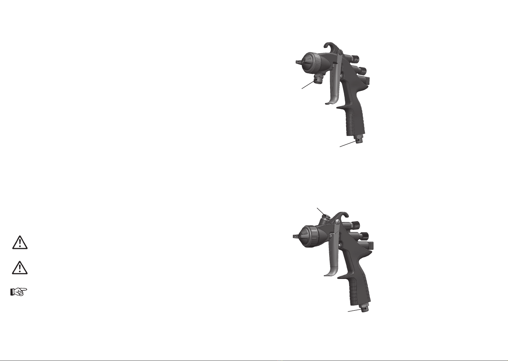
Ausführung: Materialanschluss unten
Ausführung: Materialanschluss oben
Material-
anschluss
oben
Luftanschluss
Material-
anschluss
unten
Luftanschluss
1. Befestigen Sie den Druckluftschlauch am
Luftanschluss der Spritzpistole (Pos. 35).
2. Befestigen Sie den
Materialzuführungsschlauch am
Materialanschluss (Pos. 36) der
Spritzpistole.
3. Heben Sie den Freiflusskarton auf die
gewünschte Höhe.
4. Um die im Materialschlauch befindliche
Luft entweichen zu lassen, betätigen Sie
den Abzugshebel (Pos. 31) solange, bis
ein gleichmässiger Materialstrahl aus der
Düse tritt; nun kann der Abzughebel wie-
der losgelassen werden.
5. Regulieren Sie mit der Stellschraube
(Pos. 29) (Luftmengeneinstellung) den
gewünschten Luftdruck ein.
Die Pistole ist nun betriebsbereit.
1. Befestigen Sie den Druckluftschlauch am
Luftanschluss der Spritzpistole (Pos. 35).
2. Befestigen Sie den
Materialzuführungsschlauch am
Materialanschluss (Pos. 37) der
Spritzpistole.
3. Heben Sie den Freiflusskarton auf die
gewünschte Höhe.
4. Um die im Materialschlauch befindliche
Luft entweichen zu lassen, betätigen Sie
den Abzugshebel (Pos. 31) solange, bis
ein gleichmässiger Materialstrahl aus der
Düse tritt; nun kann der Abzughebel wie-
der losgelassen werden.
5. Regulieren Sie mit der Stellschraube
(Pos. 29) (Luftmengeneinstellung) den
gewünschten Luftdruck ein.
Die Pistole ist nun betriebsbereit.

1514
Materialdruck regulieren:
Den Materialdruck können Sie durch das Verändern der Aufhäng-Höhe des
Klebstoffbehälters regulieren.
6.1 Mängel eines Spritzbildes beheben
Die folgende Tabelle zeigt Ihnen, mit welchen Einstellungen Sie das Spritzbild
beeinflussen können.
Spritzbildprobe Abweichung erforderliche Einstellung
Spritzbild ist in der Mitte
zu dick
• breitere Spritzstrahlform
einstellen
Spritzbild ist an den
Enden zu dick
• rundere Spritzstrahlform
einstellen
Spritzbild ist ziemlich
grobtropfig
• Zerstäuberluftdruck
erhöhen
Materialauftrag ist in der
Spritzbildmitte sehr dünn
• Zerstäuberluftdruck
verringern
Spritzbild ist in der Mitte
gespalten
• Düsendurchmesser erhöhen
• Zerstäuberluftdruck verringern
• Materialdruck erhöhen
Spritzbild ist sehr ellip-
tisch
• Materialdruck verringern
• Zerstäuberluftdruck erhöhen
Warnung
Beim Anschluss der bauseitigen Luftversorgung muss die Luftanschlussschraube
(Pos. 35) durch einen Maulschlüssel SW 17 gegen Verdrehen gesichert werden.
5 Bedienung
5.1 Inbetrieb- und Außerbetriebsetzen
Bevor Sie die Spritzpistole in Betrieb setzen, muss folgende Voraussetzung erfüllt
sein:
• Der Zerstäuberluftdruck muss an der Spritzpistole anstehen.
• Der Materialdruck muss an der Spritzpistole anstehen bzw. der Freiflusskarton
muss mit Material befüllt sein.
Achtung
Der Materialdruck darf nicht höher eingestellt sein als 8 bar. Der Luftdruck darf
8 bar nicht überschreiten. Arbeitsdruck ca. 2 bar.
Warnung
Die Spritzpistole muss nach Arbeitsende immer drucklos geschaltet werden. Die
unter Druck stehenden Leitungen können platzen und nahestehende Personen
durch das ausströmende Material verletzen.
Hinweis
Vor dem Inbetriebsetzen muss die Pistole gespült werden, um das Spritzmaterial
nicht zu verunreinigen.
6 Spritzbild verändern
Sie können an der SIMALFA Primus durch die folgenden Einstellungen das
Spritzbild verändern:
Material-
anschluss
Breit- bzw. Rundstrahl einstellen:
Die Regelschraube dient zur Regulierung der
Spritzstrahlbreite. Der Spritzstrahl wird durch Linksdrehen
(Ausschrauben) zum Breitstrahl, durch Rechtsdrehen
(Einschrauben) zum Rundstrahl.
Materialdurchflussmenge einstellen:
Die Materialmenge läßt sich durch Ein- bzw.
Ausschrauben der Stellschraube regeln. Die
Materialmenge wird durch Linksdrehen (Ausschrauben)
erhöht, durch Rechtsdrehen (Einschrauben) verringert.
Luftmenge regulieren:
Die Zerstäuberluftmenge läßt sich durch Ein- bzw.
Ausschrauben der Stellschraube regulieren.
Luftanschluss
angestrebtes Spritzergebnis
1716
7 Fehlersuche und -beseitigung
Warnung
Schalten Sie vor jeder Umrüstung die Zerstäuberluft sowie die Materialzufuhr zur
Spritzpistole drucklos - Verletzungsgefahr.
Fehler Ursache Abhilfe
Pistole tropft Materialnadel oder -düse ver-
schmutzt bzw. beschädigt
Nadeldichtung (Pos. 7) verun-
reinigt oder defekt.
Federkappe (Pos. 13) zu weit
nach hinten gedreht
• Reinigen bzw. ersetzen
• Nadeldichtung ersetzen
• Stellschraube etwas ein-
schrauben (Rechtsdrehen)
Stoßweiser oder
flatternder Spritz-
strahl
zu wenig Material im
Materialbehälter
Becher wird während des
Spritzvorgangs zu stark geneigt
Materialdüse lose oder beschä-
digt
• Material auffüllen
• gerader halten
• festziehen, evt. Luftver-
teilerring (Pos. 5) ersetzen
Pistole bläst in
Ruhestellung Ventilfeder (Pos. 25) oder
Ventilkegel (Pos. 24) beschädig • austauschen
8 Umrüstung und Instandsetzung
Wenn Sie das Spritzbild über die bereits erwähnten Möglichkeiten hinaus verändern
wollen, muss die Spritzpistole umgerüstet werden. Die zum Spritzmaterial passende
Luftkopf- / Materialdüse- / Nadel-Kombination bildet eine aufeinander abgestimmte
Einheit - die Düseneinlage. Tauschen Sie immer die komplette Düseneinlage aus,
damit die gewünschte Spritzbildqualität erhalten bleibt.
Warnung
Unterbrechen Sie vor jeder Umrüstung oder Instandsetzung die Luft- und Material-
zufuhr zur Spritzpistole - Verletzungsgefahr.
Hinweis
Zur Durchführung der im Folgenden aufgeführten Arbeitsschritte benutzen Sie bitte
die Explosionszeichnung (Seite 6) dieser Betriebsanleitung.
Materialdüse und Luftkopf wechseln
1. Schrauben Sie die Luftkopfmutter (Pos. 1) ab.
2. Nehmen Sie den Luftkopf (Pos. 2) ab.
3. Schrauben Sie die Materialdüse (Pos. 3) mit einem Ringschlüssel SW 11 aus
dem Pistolenkörper aus.
Hinweis
Die Montage der neuen Düseneinlage sowie der restlichen Bauteile erfolgt in um-
gekehrter Reihenfolge.
Materialnadel wechseln
1. Schrauben Sie die Federkappe (Pos. 13) ab.
2. Entnehmen Sie die Nadelfeder (Pos. 12).
3. Ziehen Sie die Materialnadel (Pos. 9) aus dem Pistolenkörper.
4. Lösen Sie die Konterschraube (Pos. 11) aus der Mitnehmerbuchse (Pos. 10)
und schrauben die Materialnadel heraus.
Die Montage erfolgt in umgekehrter Reihenfolge.
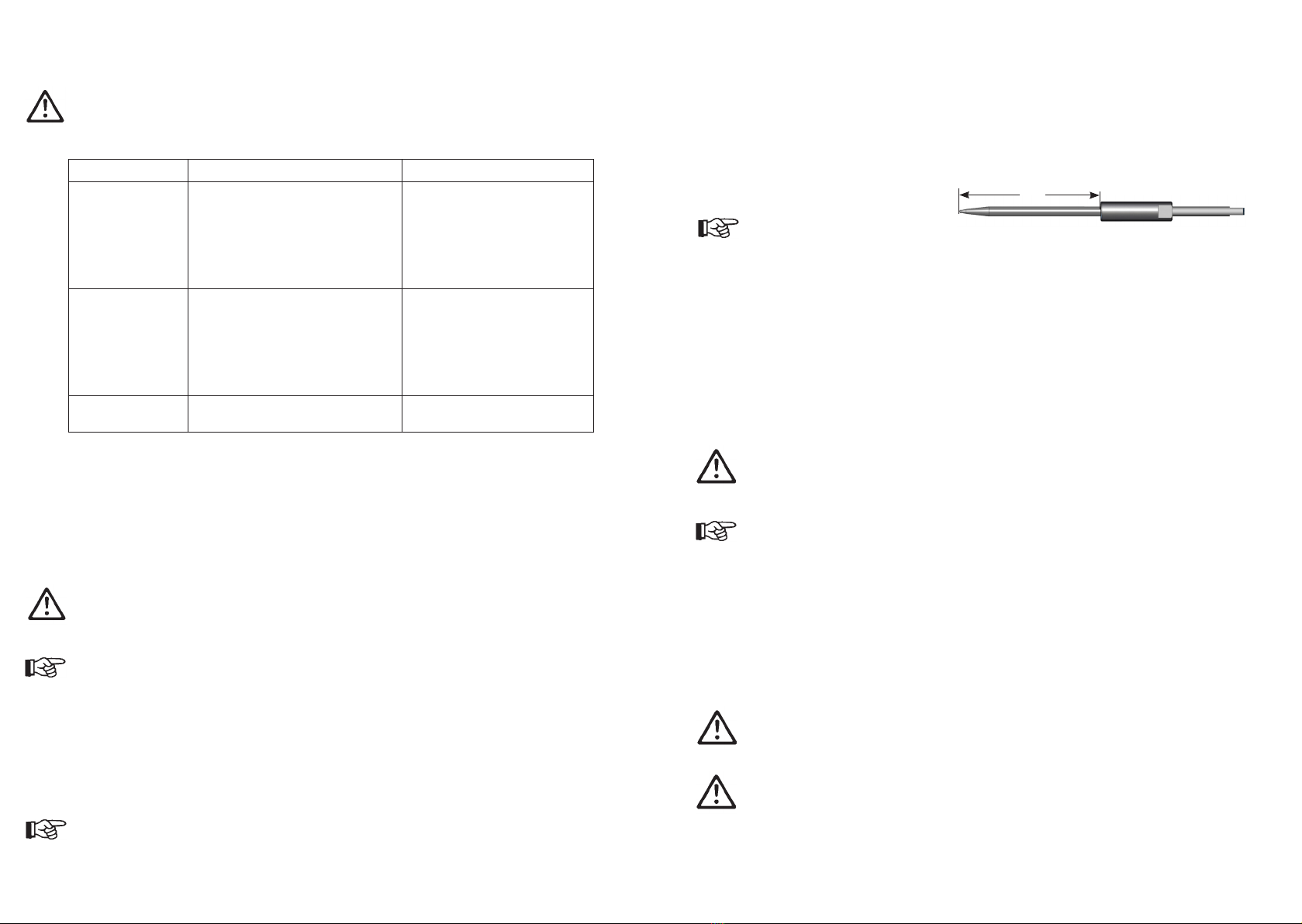
Hinweis
Das Nadeleinstellmaß bei SIMALFA Primus (MA oben) beträgt X = 69,5 mm und bei
SIMALFA Primus (MA unten) X = 78,0 mm von der Nadelspitze bis zur Mitnehmer-
buchse.
Undichte Nadelpackung austauschen
1. Entfernen Sie die Materialnadel wie oben beschrieben.
2. Schrauben Sie die Packungsschraube (Pos. 8) aus dem Pistolenkörper heraus.
3. Schrauben Sie die Hebelschaftschraube (Pos. 32) und die Hebelschraube
(Pos. 30) ab und entfernen den Abzughebel (Pos. 31).
4. Entfernen Sie die Nadeldichtung (Pos. 7). Benutzen Sie hierzu evt. einen dün-
nen Draht dessen Ende zu einem Haken umgebogen ist.
Die Montage erfolgt in umgekehrter Reihenfolge.
Achtung
Die aus dem Pistolenvorsatz entnommene Nadelpackung darf nicht wieder verwen-
det werden, da sonst eine funktionssichere Dichtwirkung nicht gewährleistet ist.
Hinweis
Alle beweglichen und gleitenden Bauteile müssen vor dem Einbau in den Pistolen-
körper mit einem säurefreien, nicht harzenden Schmiermittel eingefettet werden, wir
empfehlen ALFA Handreiniger für die Pistolenpflege.
9 Reinigung und Wartung
9.1 Grundreinigung
Damit die Lebensdauer und die Funktion der Spritzpistole lange erhalten bleibt,
muss die Spritzpistole regelmäßig gereinigt und geschmiert werden.
Achtung
Legen Sie die Spritzpistole nie in Lösemittel oder ein anderes Reinigungsmittel. Die
einwandfreie Funktion der Spritzpistole kann sonst nicht garantiert werden.
Achtung
Verwenden Sie zur Reinigung keine harten oder spitzen Gegenstände. Präzisions-
teile der Spritzpistole könnten sonst beschädigt werden und die Funktionsweise
beeinträchtigen.
X

1918
Verwenden Sie zur Reinigung der Spritzpistole nur Reinigungsmittel, die vom Her-
steller des Spritzmaterials angegeben werden und die folgenden Bestandteile nicht
enthalten:
• halogenierte Kohlenwasserstoffe (z. B. 1,1,1, Trichlorethan, Methylen-
Chlorid usw.)
• Säuren und säurehaltige Reinigungsmittel
• regenerierte Lösemittel (sog. Reinigungsverdünnungen)
• Entlackungsmittel
Die o.g. Bestandteile verursachen an galvanisierten Bauteilen chemische
Reaktionen und führen zu Korrosionsschäden.
Für Schäden, die aus einer derartigen Behandlung herrühren, übernimmt der
Hersteller keine Gewährleistung.
Eine Grundreinigung der Spritzpistole sollte
• mindestens einmal wöchentlich
• materialabhängig und je nach Verschmutzungsgrad mehrfach wöchentlich erfol-
gen. Sie erhalten so die sichere Funktion der Spritzpistole.
1. Zerlegen Sie die Pistole.
2. Reinigen Sie den Luftkopf und die Materialdüse mit einem Pinsel und dem
Reinigungsmittel.
3. Reinigen Sie alle übrigen Bauteile und den Pistolenkörper mit einem Tuch und
dem Reinigungsmittel.
4. Bestreichen Sie folgende Teile mit einem dünnen Fettfilm, wir empfehlen ALFA
Handreiniger:
• Materialnadel
• Nadelfeder
• alle gleitenden Teile und Lagerstellen
• Die beweglichen Innenteile sind wenigstens einmal wöchentlich zu fetten.
• Die Federn sollten ständig mit einem leichten Fettüberzug versehen sein.
Verwenden Sie dazu ein säurefreies, nicht harzendes Fett oder ALFA Handreiniger
und einen Pinsel. Anschließend wird die Spritzpistole in umgekehrter Reihenfolge
zusammengesetzt.
10 Entsorgung
Die Spritzmedien sowie die bei der Reinigung und Wartung anfallenden Materia-
lien sind den Gesetzen und Vorschriften entsprechend sach- und fachgerecht zu
entsorgen.
Warnung
Beachten Sie die Hinweise des Herstellers der Spritz- und Reinigungsmittel. Un-
achtsam entsorgtes Material gefährdet die Gesundheit von Mensch und Tier.
11 Technische Daten
Luftverbrauch:
Luftkopf Eingangsluftdruck
an der Pistole
Luftverbrauch
SIMALFA Primus HVLP
Materialanschluss oben
1061 3,5 bar 340 L/min.
SIMALFA Primus HVLP
Materialanschluss unten
1161 3,5 bar 340 L/min.
Technische Änderungen vorbehalten.
SIMALFA Primus-HVLP
Netto-Gewicht: 490 g
Druckbereiche, Mitteldruck:
max. Spritzdruck 1,4 bar
max. Eingangsluftdruck 3,3 bar
max. Materialdruck 8
bar
Arbeitsdruck ca. 2 bar
Druckbereiche, Niederdruck:
max. Spritzdruck 0,7 bar
max. Eingangsluftdruck 3,5 bar
max. Betriebstemperatur: 43 °C
Schallpegel
(gemessen in ca. 1 m
Abstand zur Spritzpistole): 83 dB(A)

2120
Table of contents
Exploded Drawing 6
Declaration of CE-Conformity 21
Replacement parts 22
1 General 24
1.1 Model identification 24
1.2 Intended use 24
1.3 Inappropriate use 24
2 Technical description 25
3 Safety instructions 25
3.1 Identification of safety instructions 25
3.2 General Safety instructions 25
4 Assembly 26
4.1 Supply line connection 26
5 Operation 28
5.1 Start-up and shut-down 28
6 Spray pattern adjustments 28
6.1 Correcting spray pattern flaws 29
7 Troubleshooting and fault rectification 30
8 Conversion and repair 30
9 Cleaning and maintenance 31
9.1 Basic cleaning 31
10 Disposal 32
11 Technical data 33
Declaration of EC/EU-Conformity
We, the manufacturers of the equipment, hereby declare under our sole responsibility that
the product(s) described below conform to the essential safety requirements. This declaration will
be rendered invalid if any changes are made to the equipment without prior consultation with us.
Manufacturer ALFA Klebstoffe AG
Vor Eiche 10
CH-8197 Rafz, Switzerland
Tel. +41(0) 43 433 30 30
Fax +41(0) 43 433 30 33
Email: [email protected]
www.simalfa.ch • www.alfa-klebstoffe.com
Alfa Adhesives, Inc.
15 Lincoln Street
Hawthorne, NJ 07506 USA
Telephone: 1 973.423.9266
Fax: 1 973.423.9264
Type Designation Hand-held Spray Gun SIMALFA Primus
Material connection upper V 10 707
Material connection lower V 10 708
Intended purpose Processing of sprayable media
Applied Standards and Directives
EU-Mechanical Engineering Directives 2006/42/EC
2014/34/EU (ATEX Directives)
DIN EN ISO 12100
DIN EN 1953 DIN EN 13463-1
DIN EN 1127-1 DIN EN 13463-5
Specification according 2014/34/EU
Category 2 Part marking II 2 G c T 6
Authorized with the compilation of the technical file:
Thomas Simmler, ALFA Klebstoffe, Vor Eiche 10
CH-8197 Rafz, Switzerland
Special remarks :
The named product is intended for installation in other equipment. Commissioning is prohibited
until such time as the end product has been proved to conform to the provision of the Directives
2006/42/EC.
Rafz, the 2nd of November 2016
Name: Thomas Simmler
Position: Executive Director
This Declaration does not give assurance of properties in the sense of product liability. The safety instructions
provided in the product documentation must be observed at all times.
i.V.

2322
Spare parts list:
SIMALFA Primus
HVLP-Adhesive
Material connection lower
V 10 708
Item Designation Qty. Item number
30 Lever screw 1V 10 301 09 000
31 Trigger 1 V 10 707 11 000
32 Lever shank screw 1V 10 600 20 100
33 Limiting pin 1V 10 701 12 000
34 Colour ring 1V 10 701 13 300
35 Double nipple 1V 00 101 01 000
37 Double nipple 1V 00 101 04 pre
39 Spring washer 1V 10 701 11 100
45 Seal, air volume reg. 1V 10 701 05 100
Spare parts list: (other than the given values Simalfa Primus
Material connection lower)
SIMALFA Primus
HVLP-Adhesive
Material connection upper
V 10 707
Item Designation Qty. Item number
36 Adapter for material connection 1V 10 707 05 000
37 Double nipple not applicable
40 Gun body with bushings 1V 10 707 03 000
41 Packing screw 1V 10 701 02 000
42 Material needle 1 V 10 707 04 XX3
43 Regulating screw 1V 10 701 06 000
44 Sealing ring 1 V 00 130 00 065
* Please specify the respective size when ordering spare parts.
We recommend to keep all parts printed in bold (wearing parts) in stock.
Spare parts list:
SIMALFA Primus
HVLP-Adhesive
Material connection lower
V 10 708
Item Designation Qty. Item number
1Air head nut compl. 1V 10 707 01 000
2Air head Alu (0,8 - 2,0 mm ø) 1V 01 101 86 100 *
Air head Alu (2,5 - 3,0 mm ø) V 01 101 86 200 *
3Material nozzle 1 V 10 707 02 XXX *
5 Air distributor ring 1 V 10 701 14 100
6Gun body with bushings 1V 10 708 01 000
7 Needle seal compl. 1 V 09 001 72 000
8Packing screw 1V 10 702 02 000
9Material needle 1 V 11 306 21 XX3
10 Driving bushing 1V 10 306 06 000
11 Counter screw 1V 10 701 03 000
12 Needle spring 1 V 10 701 40 000
13 Spring cap 1V 10 701 04 000
14 Sealing cone 1V 11 700 11 200
15 Lock washer 1V 10 151 23 000
16 Guide bushing 1V 10 600 05 200
17 Packing 1 V 09 101 02 020
18 Packing screw 1V 10 600 29 100
19 Regulating screw 1V 10 702 06 000
20 Valve packing gland 1V 10 701 07 000
21 Needle seal (Valve shaft seal) 1 V 11 750 20 000
22 O-ring 1 V 09 102 38 001
23 Valve shaft compl. 1V 10 701 08 300
24 Valve cone 1 V 10 701 08 000
25 Valve spring 1 V 10 701 41 000
26 Cap screw 1V 11 700 27 400
27 Bushing, air volume reg. 1V 10 701 05 000
28 Seal, air volume reg. 1V 10 701 09 000
29 Air volume regulation 1V 10 701 10 000

2524
1 General
1.1 Model identification
Models:Manual spray guns SIMALFA Primus
Type: Material connection upper V 10 707
Material connection lower V 10 708
Manufacturer: ALFA Klebstoffe AG
Vor Eiche 10
CH-8197 Rafz, Switzerland
Tel.: +41(0) 43 433 30 30
Fax: +41(0) 43 433 30 33
www.simalfa.ch • www.alfa-klebstoffe.com
Alfa Adhesives, Inc.
15 Lincoln Street
Hawthorne, NJ 07506 USA
Telephone: 1 973.423.9266
Fax: 1 973.423.9264
1.2 Intended use
The hand-held spray gun SIMALFA Primus is designed exclusively for use with water-
based adhesives, SIMALFA or ALFA dispersions.
All wetted parts are made of stainless steel.
Should the materials which you want to spray not be listed above, please contact the
manufacturer. Sprayable material should only be applied to work pieces or similar
objects.
The temperature of the material to be sprayed should at no time exceed 43° C.
The term Normal Use also implies that any and all safety warnings and instructions
laid down in these operating instructions have been read, understood and are duly
complied with.
1.3 Inappropriate use
The spray gun must not be used for purposes other than those set forth in section
1.2 Intended use.
Any other use is considered inappropriate.
Inappropriate use includes, for example:
• spraying material on persons and animals
• spraying liquid nitrogen.
2 Technical description
When the trigger (item 31) is operated, the preliminary air is opened first and then
the material needle (item 9) pulled back. Thus the spray material passes through
the nozzle. Closing takes place in reverse order. The material flow volume
depends on the nozzle diameter and the setting of the material pressure on the
free flowing system (height) pressure tank or the material pressure regulator. In
addition, the material volume can be regulated by turning the adjusting screw in or
out. Refer to 6 Changing the spray pattern for additional adjustment options.
3 Safety instructions
3.1 Identification of safety instructions
Warning
The pictogram and the urgency level “Warning“ identify a possible danger to per-
sons.
Possible consequences: Slight to severe injuries.
Attention
The pictogram and the urgency level “Attention“ identify a possible danger to
material assets.
Possible consequences: Damage to material assets.
Note
The pictogram and the urgency level “Note“ identify additional information for the
safe and efficient operation of the spray gun.
3.2 General Safety instructions
► The relevant accident prevention regulations as well as the other recognised
safety-related and occupational health and safety rules shall be - observed.
►The users must be instructed in the non-hazardous handling of the spray gun
as required.
► Usethespraygunonlyinwellventilatedrooms.Intheworkareafire,open
flame and smoking are not permitted. Spraying of easily flammable materials
(e.g. lacquers, adhesives, cleaning agents, etc.) represents an increased risk
to personal health, of explosion and fire hazards.
► Itmustbeensuredthatthespraygunisadequatelygroundedthroughacon-
ducting air hose (max. shunting resistance 106Ω).
► Beforeeachmaintenanceandrepairactivitytheairandmaterialsupplymust
be depressurised - risk of injury.
2726
Design: Material connection lower
Design: Material connection upper
material
connection
upper
air connnection
material
connection
lower
air connnection
1. Connect the air hose to the air connec-
tion nipple (item 35) of the spray gun.
2. Fasten the material inlet hose to the
material inlet (item 36) of the spray gun.
3. Lift the free flowing system container to
the desired height.
4. To let the air contained in the material
hose escape, actuate the trigger
(item 31) until a uniform jet emerges
from the nozzle; now the trigger can be
unleashed again.
5. Regulate the desired air pressure by
using the adjusting screw (air flow rate
adjustment, item 29).
The spray gun can then be put into operati-
on
► Whensprayingmaterials,neverholdhandsorotherbodyparts
in front of the pressurized nozzle of the spray gun. - Risk of injury.
► Neverpointthespraygunatpersonsoranimals
- Risk of injury.
► Followtheprocessingandsafetyinstructionsofthemanufacturersofspraying
materials and cleaning agents. Especially aggressive and caustic materials
may cause health damages.
► Particle-conveyingdischargedairmustbekeptawayfromtheworkingarea
and operating personnel. Nonetheless, be sure to wear stipulated respirators
protection and work clothes when processing materials with the spray gun.
Airborne particles can endanger your health.
►Wear eye protection during painting and cleaning.
► Wear hearing protection in the working area of the spray gun. The sound level
generated by the spray gun is approx. 83 dB (A) .
► Alwaysmakesureduringoperation,especiallyafterassemblyandmainte-
nance work, that all nuts and bolts are securely tightened.
► Useonlyoriginalsparepartsbecausethe manufacturer can only guarantee
safe and flawless function for such original parts.
► Alwaysrelievethepressurefromthespraygunafterworkiscompleted.
► Ifyouhavequestionsaboutthesafeuseofthespraygunaswellasthemate-
rial used in it, please do not hesitate to contact the manufacturer.
4 Assembly
4.1 Supply line connection
Attention
The air pressure at the gun may not exceed 8 bar since a reliable and safe opera-
tion of the spray gun is otherwise not ensured.
Warning
Material and air hoses mounted on a hose nipple must be secured with a hose
clamp in addition.
Note
The gun must be flushed before use to prevent contamination of the spraying mate-
rial.
1. Connect the air hose to the air connec-
tion nipple (item 35) of the spray gun.
2. Fasten the material inlet hose to the
material inlet (item 37) of the spray gun.
3. Lift the free flowing system container to
the desired height.
4. To let the air contained in the material
hose escape, actuate the trigger
(item 31) until a uniform jet emerges
from the nozzle; now the trigger can be
unleashed again.
5. Regulate the desired air pressure by
using the adjusting screw (air flow rate
adjustment, item 29).
The spray gun can then be put into operati-
on

2928
Adjust the material pressure:
Material pressure can be regulated by changing the height of the Clip-on adhesive
container.
6.1 Correcting spray pattern flaws
The following table shows the settings you can use to change the spray pattern.
Spray pattern test Deviation Required adjustment
Spray pattern is split in
the centre • setting a wider spray pattern
Spray pattern is too thick
at the ends • Setting a more rounded
spray pattern
The spray pattern shows
rather large droplets • Increase the nozzle air pres-
sure
Material application in
the centre of the spray
pattern is very thin
• Decrease the nozzle air
pressure
Spray pattern is split in
the centre
• Increase the nozzle diameter
• Reduce nozzle air pressure
• Increase material pressure
Spray pattern is very
elliptical • Reduce material pressure
• Increase nozzle air pressure
Warning
When connecting to the customer provided air supply the air connection screw
(item 35) must be secured against rotation with a size 17 open-end wrench.
5 Operation
5.1 Start-up and shut-down
The following requirements must have been met before you can operate the spray
gun:
• The spray air pressure must be applied at the spray gun.
• The material pressure must be applied at the spray gun or the free flowing
system container must be filled with material.
Attention
The material pressure may not be set higher than 8 bar. The air pressure may not
exceed 8 bar. Working pressure ca. 2 bar.
Warning
Always relieve the pressure from the spray gun after work is completed. The pres-
surized lines may rupture and persons standing nearby may be injured by the
escaping material.
Note
The gun must be flushed before use to prevent contamination of the spraying mate-
rial.
6 Spray pattern adjustments
You can change the spray pattern on the SIMALFA Primus by making the following
settings:
Material
connection
Adjusting wide or round spray:
The regulating screw is used to regulate the spraying
width. By turning it to the left (unscrewing), the spray
becomes wide, by turning it to the right (screwing down)
it becomes round.
Adjusting the material flow volume:
The material volume can be regulated by turning the
adjusting screw in or out. The material volume is
increased by turning it to the left (unscrewing) and
reduced by turning it to the right (screwing down).
Adjusting the air volume:
The spray air volume can be regulated by turning the
adjusting screw in or out.
Air connection
Desired Spray Pattern

3130
Changing the material needle
1. Unscrew the spring cap (item 13).
2. Remove the needle spring (item 12).
3. Pull the material needle (item 9) out of the gun body.
4. Loosen the counter screw (item 11) from the driving bushing (item 10) and
unscrew the material needle.
Assembly takes place in reverse order.
Note
The needle setting for the SIMALFA Primus (MA upper) is X = 69,5 mm and for the
SIMALFA Primus (MA lower) X = 78,0 mm from the needle tip to the driving bush-
ing.
Replacing a leaking needle packing
1. Remove the material needle as outlined above.
2. Unscrew the packing screw (item 8) from the gun body.
3. Unscrew the lever shank screw (item 32) and the lever screw (item 30) and
remove the trigger (item 31).
4. Remove the needle seal (item 7). You may need to use a thin wire with the
end bent to a hook.
Assembly takes place in reverse order.
Attention
The needle pack taken from the gun attachment may not be reused since a reliably
functioning sealing effect is no longer ensured.
Note
All moveable and sliding parts should be lubricated with a non-acidic, non-resino-
genic lubricant prior to assembly, we recommend the ALFA Hand Cleaner for the
maintenance of the spray gun.
9 Cleaning and maintenance
9.1 Basic cleaning
The spray gun must be regularly cleaned and lubricated in order to enhance its
service life and ensure the functionality of the spray gun.
Attention
Never place the spray gun in solvent or another cleaning agent. The perfect func-
tion of the spray gun can otherwise not be guaranteed.
Attention
Do not use any hard or pointed objects for cleaning. Otherwise, precision parts on
the spray gun can be damaged and and affect the functionality.
X
7 Troubleshooting and fault rectification
Warning
Before each change-over depressurize the spray air as well as the material supply
to the spray gun - risk of injury.
Fault Cause Remedy
Gun drips Material needle or nozzle dirty
or damaged
Needle seal(item 7) contami-
nated or damaged
Spring cap (item 13) turned
too far back
• Clean or replace
• Needle sealreplace
• Slightly turn down the adjust-
ment screw (clockwise)
Pulsating or
shimming spray
beam
insufficient material in the
material container
Cup is tilted too much during
the spraying process
Material nozzle loose or dam-
aged
• Refill the material
• Hold straighter
• Tighten, if necessary, replace
air distributor ring (Item 5)
Gun emits spray
in idle position Valve spring (item 25) or valve
cone (item 24) damaged • replace
8 Conversion and repair
If you want to change the spray pattern beyond the options already mentioned, the
spray gun must be converted. The air cap / material nozzle / needle combination
matching the spraying material represents an interactively tuned unit - the nozzle
insert. Always replace the entire nozzle insert to maintain the desired spray pattern
quality.
Warning
Interrupt the air and material supply to the spray gun before each conversion or
repair - risk of injury.
Note
Please refer to the exploded view (Page 6) of these operating instructions to per-
form the work steps listed below.
Changing the material nozzle and air head
1. Unscrew the air head nut (item 1).
2. Remove the air head (item 2).
3. Unscrew the material nozzle (item 3) with a wrench size 11 from the gun body.
Note
The assembly of the new nozzle insert as well as of the remaining components
takes place in reverse order.

3332
Use only those cleaning materials for cleaning the spray gun which have been pre-
scribed by the manufacturer of the spraying material and which do not contain the
following:
• halogenated hydrocarbons (e.g. 1,1,1, trichloroethane, methylene chloride, etc.)
• acids or acidic cleaning agents
• regenerated solvents(so-called cleaning thinners)
• varnish removers
The constituents named above cause chemical reactions on galvanised components
and lead to corrosion damage.
The manufacturer will not accept warranty claims for damages resulting from such
treatment.
Basic cleaning of the spray gun should be carried out::
• at least once a week
• several times a week, depending on the material and the degree of contamina-
tion. In this manner, the safe functioning of the spray gun is maintained.
1. Disassemble the gun.
2. Clean the air head and the material nozzle with a brush and the cleaning agent.
3. Clean all other components and the gun body with a cloth and the cleaning
agent.
4. Apply a thin layer of grease to the following parts, we recommend the ALFA
Hand Cleaner:
• Material needle
• Needle Spring
• All sliding parts and bearings.
• The moveable inner parts should be greased at least once a week.
• The springs should at all times be coated with a thin layer of grease.
Use non-acidic, non-resinogenic grease or ALFA Hand Cleaner and a brush. The
spray gun is then reassembled in reverse order.
10 Disposal
Spray media as well as materials used during cleaning and maintenance shall be
properly disposed of in compliance with laws and regulations.
Warning
Follow the information of the spray and cleaning agent manufacturer. Carelessly dis-
posed of material puts the health of persons and animals at risk.
11 Technical Data
Air Consumption:
Air head Intake air pressure
of the spray gun
Air Consump-
tions
SIMALFA Primus HVLP
material connection upper
1061 3,5 bar 340 L/min.
SIMALFA Primus HVLP
material connection lower
1161 3,5 bar 340 L/min.
Subject to technical alterations.
SIMALFA Primus-HVLP
Net weight: 490 g
Pressure ranges, medium pressure:
max. spraying pressure 1.4 bar
max. intake air pressure 3.3 bar
max. material pressure 8
bar
Working pressure ca. 2 bar
Pressure ranges, low pressure:
max. spraying pressure 0.7 bar
max. intake air pressure 3,5 bar
max. operating temperature: 43 °C
Sound level
(measured at approx. 1 m
distance from the spray gun): 83 dB(A)

3534
Sommaire
Vue éclatèe 6
Déclaration de conformité EC 35
Liste de pièces de rechange 36
1 Généralités 38
1.1 Dénomination du modèle 38
1.2 Utilisation courante 38
1.3 Utilisation inappropriée 38
2 Caractéristiques techniques 39
3 Consignes de sécurité 39
3.1 Signalisation de sécurité 39
3.2 Consignes générales de sécurité 39
4 Assemblage 40
4.1 Raccordement des conduits d‘alimentation 40
5 Manipulation 42
5.1 Mise en et arrêt de service 42
6 Régulation du jet 42
6.1 Correction d’un jet imparfait 43
7 Défauts de fonctionnement: causes et remèdes 44
8 Conversion et maintenance 44
9 Nettoyage et entretien 45
9.1 Nettoyage complet 45
10 Fluides résiduels 46
11 Données techniquees 47
Déclaration de conformité CE/UE
En tant que fabricant de cet appareil, nous déclarons en toute responsabilité que le produit
décrit ci-dessous est conforme aux exigences de sécurité et de protection de la santé actuellement
en vigueur. Toute modification sans autorisation de notre part ou utilisation inadéquate de
l'appareil, annulent la validité de cette déclaration.
Fabricant ALFA Klebstoffe AG
Vor Eiche 10
CH-8197 Rafz, Switzerland
Tel. +41(0) 43 433 30 30
Fax +41(0) 43 433 30 33
Email: [email protected]
www.simalfa.ch • www.alfa-klebstoffe.com
Alfa Adhesives, Inc.
15 Lincoln Street
Hawthorne, NJ 07506 USA
Telephone: 1 973.423.9266
Fax: 1 973.423.9264
Dénomination du modèle Pistolets de pulvérisation manuels SIMALFA Primus
Raccordement matière par le haut V 10 707
Raccordement matière par le bas V 10 708
Utilisation Application de matières pulvérisables
Normes et directives appliquées
Directive UE sur les machines 2006/42/EC
2014/34/CE (directives ATEX)
DIN EN ISO 12100
DIN EN 1953 DIN EN 13463-1
DIN EN 1127-1 DIN EN 13463-5
Normes et directives appliquées 2014/34/CE
Catégorie 2 désignation de
l'appareil II 2 G c T 6
Personne chargée de la compilation des documents techniques :
Thomas Simmler, ALFA Klebstoffe, Vor Eiche 10
CH-8197 Rafz, Switzerland
Indications particulières:
Le produit est conçu pour être intégré à un autre équipement. La mise en service n'est
pas autorisée avant l'établissement de la conformité du produit final avec la directive
2006/42/EC.
Rafz, le 2 novembre 2016
Nom: Thomas Simmler
Position dans l'entreprise: Directeur d'execution
Cette déclaration ne constitue pas un engagement de responsabilité dans le sens de la garantie du produit. Les
consignes de sécurité contenues dans les instructions de service devront être respectées.
i.V.

3736
Pièces de rechange:
SIMALFA Primus
HVLP-Colle
à raccordement matière par le bas
V 10 708
N° Description Pce. Pièce N°
30 Contre-vis de la gâchette 1V 10 301 09 000
31 Gâchette 1V 10 707 11 000
32 Vis à tige creuse de la gâchette 1V 10 600 20 100
33 Goupille de limitation 1V 10 701 12 000
34 Anneau de couleur 1V 10 701 13 300
35 Raccord double 1V 00 101 01 000
37 Raccord double 1V 00 101 04 pre
39 Disque de ressort 1V 10 701 11 100
45 Joint rég. de la qtité d’air 1V 10 701 05 100
Pièces de rechange: (différent du raccord de matière Simalfa Primus ci-dessous)
SIMALFA Primus
HVLP-Colle
à raccordement matière par le haut
V 10 707
N° Description Pce. Pièce N°
36 Adaptateur pour raccord de matière 1V 10 707 05 000
37 Raccord double supprimé
40 Corps de pistolet avec douilles 1V 10 707 03 000
41 Vis de garniture 1V 10 701 02 000
42 Aiguille de matière 1 V 10 707 04 XX3
43 Vis de réglage 1V 10 701 06 000
44 Bague d‘étanchéité 1V 00 130 00 065
* Indiquez toujours le calibre des pièces de rechange lors de la commande.
Nous vous recommandons de prévoir en stock les kits de réparation.
Pièces de rechange:
SIMALFA Primus
HVLP-Colle
à raccordement matière par le bas
V 10 708
N° Description Pce. Pièce N°
1Ecrou de tête à air complet 1 V 10 707 01 000
2tête à air Alu (0,8 - 2,0 mm ø) 1V 01 101 86 100 *
tête à air Alu (2,5 - 3,0 mm ø) V 01 101 86 200 *
3 Buse à matière 1 V 10 707 02 XXX *
5Bague de distribution d‘air 1 V 10 701 14 100
6Corps de pistolet avec douilles 1V 10 708 01 000
7 Joint d`aiguille complet 1 V 09 001 72 000
8Vis de garniture 1V 10 702 02 000
9 Aiguille de matière 1 V 11 306 21 XX3
10 Douille d'entraînement 1V 10 306 06 000
11 Contre-vis 1 V 10 701 03 000
12 Resort d'aiguille 1 V 10 701 40 000
13 Capuchon du ressort 1V 10 701 04 000
14 Cône d'étanchéité 1V 11 700 11 200
15 Anneau de retenue 1V 10 151 23 000
16 Canon de guidage 1V 10 600 05 200
17 Garniture 1 V 09 101 02 020
18 Vis de garniture 1V 10 600 29 100
19 Vis de réglage 1V 10 702 06 000
20 Presse étoupe de valve 1V 10 701 07 000
21 Joint d‘aiguille (Joint Tige de valve) 1 V 11 750 20 000
22 Joint torique 1 V 09 102 38 001
23 Tige de valve complet 1V 10 701 08 300
24 Cône de valve 1 V 10 701 08 000
25 Ressort de valve 1 V 10 701 41 000
26 Vis cylindrique 1V 11 700 27 400
27 Douille rég. de la qtité d'air 1V 10 701 05 000
28 Joint rég. de la qtité d'air 1V 10 701 09 000
29 réglage volume d’air 1V 10 701 10 000

3938
1 Généralités
1.1 Dénomination du modèle
Modèle: Pistolets de pulvérisation manuel SIMALFA Primus
Type: raccordement matière par le haut V 10 707
raccordement matière par le bas V 10 708
Fabricant: ALFA Klebstoffe AG
Vor Eiche 10
CH-8197 Rafz, Switzerland
Tel.: +41(0) 43 433 30 30
Fax: +41(0) 43 433 30 33
www.simalfa.ch • www.alfa-klebstoffe.com
Alfa Adhesives, Inc.
15 Lincoln Street
Hawthorne, NJ 07506 USA
Telephone: 1 973.423.9266
Fax: 1 973.423.9264
1.2 Utilisation courante
Le pistolet de pulvérisation manuel SIMALFA Primus est exclusivement destiné à
l‘application dé adhésif à base aqeuse, SIMALFA ou ALFA dispersion.
Les pièces en contact avec la matière sont en acier inoxydable et permettent
l‘application de matières hydrosolubles.
Si la matière que vous souhaitez pulvériser n‘est pas mentionnée ici, adressez-vous
au fabricant. La matière pulvérisable doit exclusivement être appliquée sur des objets
ou pièces á usiner.
La température de la matière de pulvérisation ne doit pas dépasser 43°.
Le terme „utilisation courante“ présuppose que toutes les instructions et consignes
d‘utilisation ont été lues, comprises et suivies.
1.3 Utilisation inappropriée
Les pistolets ne doivent pas être utilisés à d’autres fins que celles décrites par le
paragraphe sur l’utilisation courante. Toute autre utilisation est considérée inap- pro-
priée.
Sont inclues dans cette catégorie:
• la pulvérisation de produit sur des personnes et des animaux
• la pulvérisation d’azote liquide
2 Caractéristiques techniques
Lors de l’actionnement du levier de détente (pos. 31), l’air initial est d’abord ouvert
et l’aiguille à matière (pos. 9) est ensuite retirée. Le matériel devant être pulvérisé
arrive ainsi à travers la buse.
La fermeture s’effectue dans l’ordre inverse.
Le débit de matière dépend du diamètre de la buse et du réglage de la pression
de la matière sur le système à flux libre (hauteur) du récipient de pression ou le
régulateur de pression.
De plus, il est possible d’ajuster la quantité de matériel en vissant ou dévissant la
vis de réglage. Pour plus de possibilités de réglage, voir 6 Modifier image proje-
tée.
3 Consignes de sécurité
3.1 Signalisation de sécurité
Danger
Le symbole et l’avertissement „danger“ signalisent un risque potentiel pour les
personnes. Conséquences possibles: blessures graves ou légères.
Attention
Le symbole et l’avertissement „attention“ signalisent un risque potentiel pour les
biens. Conséquences possibles: dégâts matériels.
Recommandation
Le symbole et l’avertissement „recommandation“ signalisent les informations
complémentaires, nécessaires au bon fonctionnement et à la sécurité d’utilisation
du pistolet.
3.2 Consignes générales de sécurité
► Respectez les mesures de prévention des accidents ainsi que toutes les
mesures de sécurité en vigueur et les réglements de la médecine du travail.
►Les utilisateurs doivent avoir été formés à utiliser le pistolet pulvérisateur sans
danger.
► N‘utilisez le pistolet que dans une zone de travail bien ventilée. Toute source
d‘étincelle est interdite dans la zone de travail. L‘application de produits très
inflammables (laques, adhésifs et solvants) augmente les risques d‘explosion
et d‘incendie.
► Vous devrez veiller à ce que la mise à la terre du pistolet de pulvérisation soit
correctement assurée par un flexible d‘air conductible (résistance max. 106Ω).
►Fermez l‘alimentation en matière et en air du pistolet avant tous travaux de
maintenance ou d‘entretien – risque de blessure.
Table of contents
Languages:
Other SIMALFA Paint Sprayer manuals


