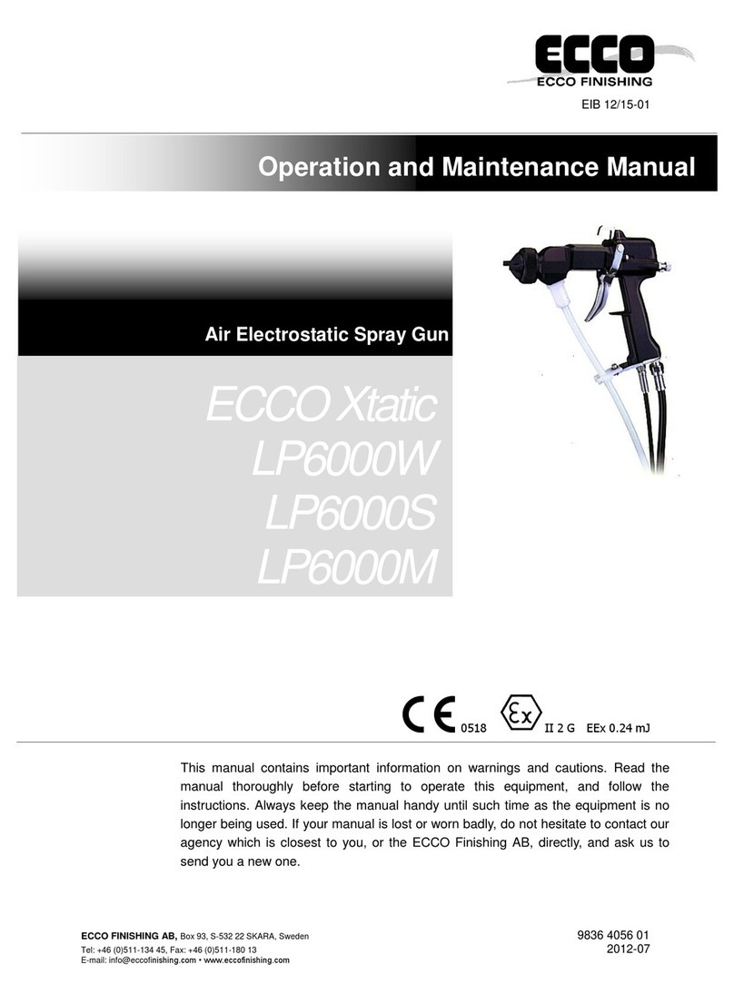
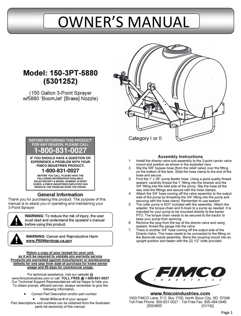
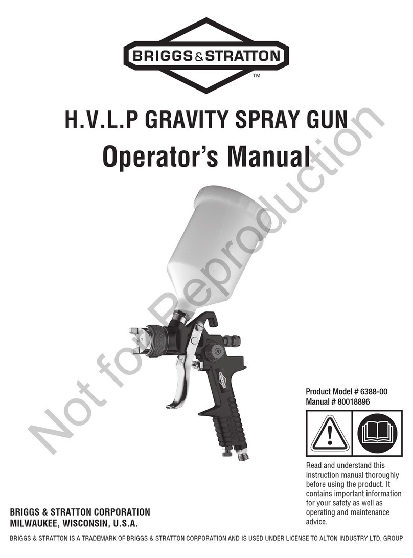
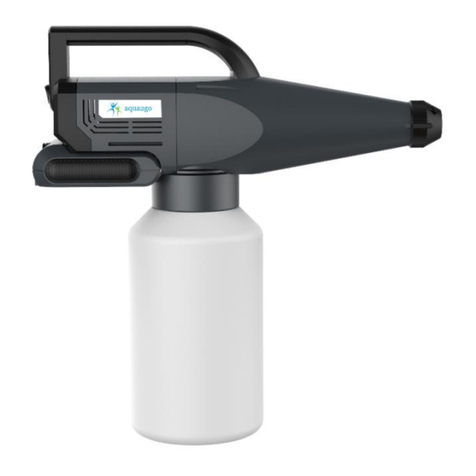
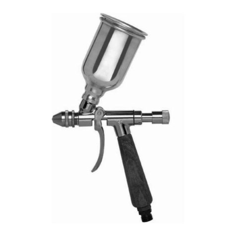
SIMALFA G1 User manual

SIMALFA®
Betriebsanleitung / Operating Instructions /
Instructions de Service / Istruzione per l’uso /
Instrukcja Obsługi / Instrucciones de Servicio
Spritzpistole / Spray Gun /
Pistolet de Pulvérisation / Pistola a spruzzo /
Pistolet natryskowy / Pistola de Pulverizacion
SIMALFA G1
Materialanschluss unten / Material connection, lower /
Raccord d’arrivée de matière par le bas / Collegamento del
materiale sotto / Przyłącze materiału dolne /
conexión de material por el inferior
Alfa Adhesives, Inc.
15 Lincoln Street
Hawthorne, NJ 07506 USA
Telephone: 1 973.423.9266
Fax: 1 973.423.9264
Email: [email protected]
www.simalfa.com
ALFA Klebstoffe AG
Vor Eiche 10
CH-8197 Rafz, Switzerland
Tel. +41(0) 43 433 30 30
Fax +41(0) 43 433 30 33
Email: [email protected]
www.simalfa.ch • www.alfa-klebstoffe.com REV. 09/10

SIMALFA G1
Stand: September 2008
Achtung!
Neue Luftmengenregulierung ab
Pistolen-Nr. 291 613 verbaut.
Neue Nadelpackung ab Pistolen-Nr.
303 111 eingebaut.
Materialanschluss unten

EG-Konformitätserklärung
Wir, der Gerätehersteller, erklären in alleiniger Verantwortung, dass das Produkt in der
untenstehenden Beschreibung den einschlägigen grundlegenden Sicherheits- und
Gesundheitsanforderungen entspricht. Bei einer nicht mit uns abgestimmten Änderung an dem
Gerät oder bei einer unsachgemäßen Verwendung verliert diese Erklärung ihre Gültigkeit.
Hersteller ALFA Klebstoffe AG
Vor Eiche 10
CH-8197 Rafz, Switzerland
Tel. +41(0) 43 433 30 30
Fax +41(0) 43 433 30 33
Email: [email protected]
www.simalfa.ch • www.alfa-klebstoffe.com
Alfa Adhesives, Inc.
15 Lincoln Street
Hawthorne, NJ 07506 USA
Telephone: 1 973.423.9266
Fax: 1 973.423.9264
Email: [email protected] • www.simalfa.com
Typenbezeichnung Handspritzpistole SIMALFA G1 V 11 752 00 000
Verwendungszweck Verarbeitung spritzbarer Materialien
Angewandte Normen und Richtlinien
EG-Maschinenrichtlinien 2006 / 42 / EG
94 / 9 EG (ATEX Richtlinien)
EN ISO 12100 Teil 1
EN ISO 12100 Teil 2 DIN EN 1953
DIN EN 1127-1 DIN EN 13463-1
Spezifikation im Sinne der Richtlinie 94 / 9 / EG
Kategorie 2 Gerätebezeichnung II 2 G c T 6
Bevollmächtigt mit der Zusammenstellung der technischen Unterlagen:
Thomas Simmler, ALFA Klebstoffe, Vor Eiche 10
CH-8197 Rafz, Switzerland
Besondere Hinweise :
Das Produkt ist zum Einbau in ein anderes Gerät bestimmt. Die Inbetriebnahme ist so lange
untersagt, bis die Konformität des Endproduktes mit der Richtlinie 2006 / 42 / EG festgestellt ist.
Rafz, den 01. Januar 2010
Name: Thomas Simmler
Stellung im Betrieb: Geschäftsführer
Diese Erklärung ist keine Zusicherung von Eigenschaften im Sinne der Produkthaftung. Die Sicherheitshinweise
der Produktdokumentation sind zu beachten.
i.V.
Declaration of CE-Conformity
We, the manufacturers of the equipment, hereby declare under our sole responsibility that
the product(s) described below conform to the essential safety requirements. This declaration will
be rendered invalid if any changes are made to the equipment without prior consultation with us.
Manufacturer ALFA Klebstoffe AG
Vor Eiche 10
CH-8197 Rafz, Switzerland
Tel. +41(0) 43 433 30 30
Fax +41(0) 43 433 30 33
Email: [email protected]
www.simalfa.ch • www.alfa-klebstoffe.com
Alfa Adhesives, Inc.
15 Lincoln Street
Hawthorne, NJ 07506 USA
Telephone: 1 973.423.9266
Fax: 1 973.423.9264
Email: [email protected] • www.simalfa.com
Type Designation Hand-held Spray Gun SIMALFA G1 V 11 752 00 000
Intended purpose Processing of sprayable media
Applied Standards and Directives
EU-Mechanical Engineering Directives 2006 / 42 / EC
94 / 9 EC (ATEX Directives)
EN ISO 12100-1
EN ISO 12100-2 DIN EN 1953
DIN EN 1127-1 DIN EN 13463-1
Specification according 94 / 9 / EC
Category 2 Part marking II 2 G c T 6
Authorized with the compilation of the technical file:
Thomas Simmler, ALFA Klebstoffe, Vor Eiche 10
CH-8197 Rafz, Switzerland
Special remarks :
The named product is intended for installation in other equipment. Commissioning is prohibited
until such time as the end product has been proved to conform to the provision of the Directives
2006 / 42 / EC.
Rafz, the 1st of January 2010
Name: Thomas Simmler
Position: Executive Director
This Declaration does not give assurance of properties in the sense of product liability. The safety instructions
provided in the product documentation must be observed at all times.
i.V.

Déclaration de conformité EC
En tant que fabricant de cet appareil, nous déclarons en toute responsabilité que le produit
décrit ci-dessous est conforme aux exigences de sécurité et de protection
de la santé actuellement en vigueur. Toute modification sans autorisation de notre part ou utilisati-
on inadéquate de l'appareil, annulent la validité de cette déclaration.
Fabricant ALFA Klebstoffe AG
Vor Eiche 10
CH-8197 Rafz, Switzerland
Tel. +41(0) 43 433 30 30
Fax +41(0) 43 433 30 33
Email: [email protected]
www.simalfa.ch • www.alfa-klebstoffe.com
Alfa Adhesives, Inc.
15 Lincoln Street
Hawthorne, NJ 07506 USA
Telephone: 1 973.423.9266
Fax: 1 973.423.9264
Email: [email protected] • www.simalfa.com
Dénomination du modèle Pistolet de pulvérisation manuel SIMALFA G1 V 11 752 00 000
Utilisation Application de matières pulvérisables
Normes et directives appliquées
Directive UE sur les machines 2006 / 42 / EC
94 / 9 EC (directives ATEX)
EN ISO 12100-1
EN ISO 12100-2 DIN EN 1953
DIN EN 1127-1 DIN EN 13463-1
Normes et directives appliquées 94 / 9 / EC
Catégorie 2 désignation de
l'ap pareil II 2 G c T 6
Personne chargée de la compilation des documents techniques :
Thomas Simmler, ALFA Klebstoffe, Vor Eiche 10
CH-8197 Rafz, Switzerland
Indications particulières:
Le produit est conçu pour être intégré à un autre équipement. La mise en service n'est
pas autorisée avant l'établissement de la conformité du produit final avec la directive
2006 / 42 / EC.
Rafz, le 1 janvier 2010
Nom: Thomas Simmler
Position dans l'entreprise: Directeur d'execution
Cette déclaration ne constitue pas un engagement de responsabilité dans le sens de la garantie
du produit. Les consignes de sécurité contenues dans les instructions de service devront être
respectées.
i.V.
Dichiarazione di conformità CE
Noi, il costruttore, dichiariamo sotto la nostra esclusiva responsabilità che il prodotto qui di
seguito descritto corrisponde ai requisiti di sicurezza e di salute essenziali in materia. In caso di
modifica del prodotto non concordata con noi o in caso di uso improprio, la presente dichiarazione
cessa di essere valida.
Costruttore ALFA Klebstoffe AG
Vor Eiche 10
CH-8197 Rafz, Switzerland
Tel. +41(0) 43 433 30 30
Fax +41(0) 43 433 30 33
Email: [email protected]
www.simalfa.ch • www.alfa-klebstoffe.com
Alfa Adhesives, Inc.
15 Lincoln Street
Hawthorne, NJ 07506 USA
Telephone: 1 973.423.9266
Fax: 1 973.423.9264
Email: [email protected] • www.simalfa.com
Designazione del tipo Pistola a spruzzzo SIMALFA G1 V 11 752 00 000
Uso previsto Applicazione di materiali spruzzabili
Norme e direttive applicate
Direttive macchine 2006 / 42 / EC
94 / 9 EC (direttive ATEX)
EN 12100 parte 1
EN 12100 parte 2 DIN EN 1953
DIN EN 1127-1 DIN EN 13463 - 1
Specifica ai sensi della direttiva 94 / 9 / EC
Categoria 2 Designazione dell'ap-
parecchio II 2 G c T 6
Autorizzato alla raccolta della documentazione tecnica:
Thomas Simmler, ALFA Klebstoffe, Vor Eiche 10
CH-8197 Rafz, Switzerland
Peculiarità :
Il prodotto è previsto per essere incorporato in un altro apparecchio. La messa in sevizio non è consen-
tita fino a quando non è stata constatata la conformità del prodotto finale con la direttiva 2006 / 42 / EC.
Rafz, il 1 gennaio 2010
per delega
Nome e cognome: Thomas Simmler
Posizione aziendale: Gerente
La presente dichiarazione non è una garanzia di caratteristiche nel senso della responsabilità del
prodotto. Rispettare rigorosamente le avvertenze di sicurezza della documentazione del prodotto.

Deklaracja zgodności WE
Jako producent urządzenia oświadczamy z pełną odpowiedzialnością, że wymieniony
poniżej produkt spełnia odpowiednie podstawowe wymogi w zakresie bezpieczeństwa i ochrony
zdrowia. W przypadku dokonania zmian w urządzeniu bez porozumienia z producentem lub
użytkownia urządzenia niezgodnie z jego przeznaczeniem, niniejsza deklaracja traci ważność.
Producent ALFA Klebstoffe AG
Vor Eiche 10
CH-8197 Rafz, Switzerland
Tel. +41(0) 43 433 30 30
Fax +41(0) 43 433 30 33
Email: [email protected]
www.simalfa.ch • www.alfa-klebstoffe.com
Alfa Adhesives, Inc.
15 Lincoln Street
Hawthorne, NJ 07506 USA
Telephone: 1 973.423.9266
Fax: 1 973.423.9264
Email: [email protected] • www.simalfa.com
Oznaczenie typu Ręczny pistolet natryskowy SIMALFA G1 V 11 752 00 000
Przeznaczenie Nanoszenie materiałów metodą natryskową
Zastosowane normy i dyrektywy
Dyrektywa WE dla maszyn 2006 / 42 / EC
94 / 9 EC (dyrektywa ATEX)
EN 12100 część 1
EN 12100 część 2 DIN EN 1953
DIN EN 1127-1 DIN EN 13463-1
Specyfikacja w rozumieniu dyrektywy 94 / 9 / EC
Kategoria 2 Oznaczenie
urządzenia II 2 G c T 6
Osoba upoważniona do zestawienia dokumentacji technicznej:
Thomas Simmler, ALFA Klebstoffe, Vor Eiche 10
CH-8197 Rafz, Switzerland
Informacje szczególne :
Produkt jest przeznaczony do montażu w innym urządzeniu. Uruchomienie może nastąpić dopie-
ro po potwierdzeniu zgodności produktu końcowego z dyrektywą 2006 / 42 / EC.
Rafz, 01 stycznia 2010
z up.
Nazwisko: Thomas Simmler
Zajmowane stanowisko: Dyrektor
Niniejsza deklaracja nie stanowi potwierdzenia właściwości produktu. Należy stosować się do
zasad bezpieczeństwa zamieszczonych w dokumentacji produktu.
Declaración de conformidad CE
Como fabricante de este aparato, certificamos bajo nuestra plena responsabilidad
que el producto descrito más abajo cumple con los requisitos de seguridad y protección de la
salud en vigor. Cualquier modificación sin autorización previa o uso inadecuado del aparato anu-
lan la validez de esta declaración.
Fabricante ALFA Klebstoffe AG
Vor Eiche 10
CH-8197 Rafz, Switzerland
Tel. +41(0) 43 433 30 30
Fax +41(0) 43 433 30 33
Email: [email protected]
www.simalfa.ch • www.alfa-klebstoffe.com
Alfa Adhesives, Inc.
15 Lincoln Street
Hawthorne, NJ 07506 USA
Telephone: 1 973.423.9266
Fax: 1 973.423.9264
Email: [email protected] • www.simalfa.com
Denominación del
modelo
Pistolas de pulverización SIMALFA G1 V 11 752 00 000
Uso aplicación de materiales pulverizables
Normas y directivas aplicadas
Directiva EU sobre las máquinas 2006 / 42 / EC
94 / 9 EC (directivas ATEX)
EN ISO 12100-1
EN ISO 12100-2 DIN EN 1953
DIN EN 1127-1 DIN EN 13463-1
Especificación en el sentido de 94 / 9 / EC
Categoría 2 designación del apa-
rato II 2 G c T 6
Persona autorizada para la compilación de la documentación técnica:
Thomas Simmler, ALFA Klebstoffe, Vor Eiche 10
CH-8197 Rafz, Switzerland
Indicaciones particulares:
Este aparato está diseñado para integrarse a otro equipo. La puesta en marcha no se autoriza
hasta que la conformidad del producto final con los requisitos de la directiva
2006 / 42 / EC no haya sido establecida.
Rafz, el 01 de enero 2010
Nombre:Thomas Simmler
Puesto: Director
Esta declaración no constituye una declaración de responsabilidad en cuanto a la caracteristicas estipuladas en
la garantía del aparato. Las consignas de seguridad de las instrucciones de uso deben seguirse.
i.V.

Pos. Ersatzteil-Nr. Bezeichnung
1 V 11 750 15 000 Überwurfmutter kompl.
2 V 01 101 86 . . 6* 6-Loch-Niederdruckluftkopf
3 V 11 750 60 . . 3* Materialdüse
4 V 09 103 33 001 O-Ring
5 V 11 700 09 100 Luftverteilerring
6 V 11 750 02 000 Vorderteil kompl.
7 V 11 700 24 000 Körperdichtung
8 V 09 102 33 009 O-Ring
11 V 11 700 01 000 Pistolenkörper kompl.
12 V 11 700 11 000 Regelschraube Rund-Breitstrahleinstellung
13 V 09 103 14 001 O-Ring
14 V 11 700 12 100 Spindelbuchse
15 V 09 101 02 020 Packung
16 V 10 302 02 000 Stopfbuchse
17 V 11 700 13 000 Stellknopf
18 V 11 700 13 100 Zylinderschraube
19 V 09 002 15 000 Ventildichtung
20 V 11 700 23 104 Ventilstopfbuchse
21 V 11 700 05 303 Ventilschaft
22 V 11 700 05 000 Ventilkegel kompl.
23 V 11 700 16 100 Ventilfeder
24 V 11 601 13 000 Scheibe
25 V 09 103 85 001 O-Ring
26 V 11 700 06 100 Federbuchse
27 V 11 750 30 . . 3* Materialnadel kompl.
28 V 10 151 53 000 Nadelfeder
29 V 11 700 22 000 Stellschraube kompl.
36 V 11 700 01 203 Führungsstift (Luftmengeneinstellung)
37 V 11 700 07 000 Luftrohr kompl.
38 V 11 750 19 000 Pistolengriff m. Platte
39 V 11 700 08 003 Anschlussnippel (Luftanschluss)
40 V 11 700 26 100 Hebelschaftschraube
41 V 10 301 09 000 Hebelschraube
42 V 11 601 23 000 Sicherungsscheibe
Ersatzteilliste: SIMALFA G1 V 11 752 03 . . 3
Materialanschluss unten
Pos. Ersatzteil-Nr. Bezeichnung
43 V 11 700 17 005 Mitnehmerbolzen
44 V 11 700 14 100 Abzugshebel
45 V 11 700 26 200 Federscheibe
46 V 11 750 03 003 Doppelnippel
48 V 09 103 88 001 O-Ring
49 50 293 Schlauchset 3,5 m (Optional) ohne Abbildung
50 V 11 750 21 003 Packungsschraube
51 V 09 102 38 001 O-Ring
52 V 11 750 20 000 Nadeldichtung
53 V 09 102 41 000 O-Ring
54 V 11 750 04 003 Packungsgehäuse
50-54 V 11 750 04 000 Nadelpackung kompl.
55 V 11 700 27 100 Abdichthülse (Luftmengeneinstellung)
56 V 11 700 27 200 Packungsring (Luftmenge)
57 V 11 700 27 600 Packung
58 V 11 700 27 300 Dichtschraube (Luftmengenregelung)
59 V 11 700 27 500 Stellschraube (Luftmengeneinstellung)
60 V 11 700 27 400 Zylinderschraube
65 51 435 Reinigungs-Set
* Bei Ersatzteillieferung bitte entsprechende Größe angeben.

Inhaltsverzeichnis
1 Allgemeines
1.1 Kennzeichnung des Modells
1.2 Bestimmungsgemäße Verwendung
1.3 Sachwidrige Verwendung
2 Technische Beschreibung
3 Sicherheitshinweise
3.1 Kennzeichnung der Sicherheitshinweise
3.2 Allgemeine Sicherheitshinweise
4 Montage / Instandsetzung
4.1 Versorgungsleitungen anschließen
4.2 Wechseln der gesamten Nadelpackung
5 Bedienung
5.1 Sicherheitshinweise
5.2 Inbetrieb- und Außerbetriebsetzen
5.3 Spritzbildprobe erzeugen
5.4 Spritzbild verändern
5.5 Spritzpistole umrüsten
5.6 Mängel eines Spritzbildes beheben
6 Reinigung und Wartung
6.1 Sicherheitshinweise
6.2 Grundreinigung
6.3 Routinereinigung
7 Fehlersuche und -beseitigung
8 Entsorgung
9 Technische Daten
2
1 Allgemeines
1.1 Kennzeichnung des Modells
Modell: Handspritzpistole SIMALFA G1
Typ: G1 V 11 752 00 000
Zubehör: Schlauchset 3,5 m (Optional)
Hersteller: ALFA Klebstoffe AG
Vor Eiche 10
CH-8197 Rafz, Switzerland
Tel. +41(0) 43 433 30 30
Fax +41(0) 43 433 30 33
www.simalfa.ch • www.alfa-klebstoffe.com
Alfa Adhesives, Inc.
15 Lincoln Street
Hawthorne, NJ 07506 USA
Telephone: 1 973.423.9266
Fax: 1 973.423.9264
1.2 Bestimmungsgemäße Verwendung
Die Handspritzpistole SIMALFA G1 dient ausschließlich der Verarbeitung von Kleb-
stoffen auf Wasserbasis, wie SIMALFA oder ALFA Dispersionen.
Sämtliche materialführenden Teile sind aus Edelstahl-rostfrei gefertigt.
Sind die Materialien, die Sie verspritzen wollen, hier nicht aufgeführt, wenden Sie
sich bitte an den Hersteller.
Die spritzbaren Materialien dürfen lediglich auf Werkstücke bzw. Gegenstände
aufgetragen werden.
Die Temperatur des Spritzmaterials darf 43°C grundsätzlich nicht überschreiten.
Die bestimmungsgemäße Verwendung schließt auch ein, dass alle Hinweise und
Angaben der vorliegenden Betriebsanleitung gelesen, verstanden und beachtet wer-
den.
Beim Betreiben des Gerätes sind die Vorgaben dieser Betriebsanleitung unbedingt
einzuhalten.
Die vorgeschriebenen Inspektions- und Wartungsintervalle sind einzuhalten. Die An-
gaben auf den Geräteschildern bzw. die Angaben in dem Kapitel technische Daten
sind unbedingt einzuhalten und dürfen nicht überschritten werden. Anwendungen,
bei denen der Ausfall des Gerätes zu einer Personengefährdung führen könnten,
sind betreiberseitig entsprechende Sicherheitsmaßnahmen vorzusehen.
Falls im Betrieb Auffälligkeiten erkannt werden, muss das Gerät sofort stillgesetzt
werden und es ist mit dem Hersteller Rücksprache zu halten.

1.3 Sachwidrige Verwendung
Die Spritzpistole darf nicht anders verwendet werden, als es im Abschnitt 1.2
Bestimmungsgemäße Verwendung geschrieben steht.
Jede andere Verwendung ist sachwidrig.
Zur sachwidrigen Verwendung gehören z.B.:
• das Verspritzen von Materialien auf Personen und Tiere
• das Verspritzen von flüssigem Stickstoff.
2 Technische Beschreibung
SIMALFA G1
Bei einem Eingangsdruck von 3,3 bar beträgt der Spritzdruck 0,7 bar.
Bei Betätigung des Abzughebels (Pos. 44) wird zuerst die Vorluft geöffnet und
danach die Materialnadel (Pos. 27) zurückgezogen. Hierdurch gelangt das Spritz-
material durch die Düse. Das Schließen erfolgt in umgekehrter Reihenfolge. Die
Materialdurchflussmenge ist abhängig vom Durchmesser der Düse und der Auf-
häng-Höhe des Freiflusskartons. Zusätzlich läßt sich die Materialmenge durch
Ein- bzw. Ausschrauben der Stellschraube (Pos. 29) regeln. Zu weiteren
Einstellungsmöglichkeiten siehe 5.4 Spritzbild verändern.
3 Sicherheitshinweise
3.1 Kennzeichnung der Sicherheitshinweise
Warnung
Das Piktogramm und die Dringlichkeitsstufe “Warnung“ kennzeichnen eine mög-
liche Gefahr für Personen.
Mögliche Folgen: schwere oder leichte Verletzungen.
Achtung
Das Piktogramm und die Dringlichkeitsstufe “Achtung“ kennzeichnen eine mög-
liche Gefahr für Sachwerte.
Mögliche Folgen: Beschädigung von Sachen.
Hinweis
Das Piktogramm und die Dringlichkeitsstufe “Hinweis“ kennzeichnen zusätzliche
Informationen für das sichere und effiziente Arbeiten mit der Spritzpistole.
3.2 Allgemeine Sicherheitshinweise
Die einschlägigen Unfallverhütungsvorschriften sowie die sonstigen anerkannten
sicherheitstechnischen und arbeitsmedizinischen Regeln sind einzuhalten.
Benutzen Sie die Spritzpistole nur in gut belüfteten Räumen mit einer entspre-
chenden Absaugung. Im Arbeitsbereich ist Feuer, offenes Licht und Rauchen ver-
boten.
3
Beim Verspritzen leichtentzündlicher Materialien (z. B. lösungsmittelhaltige
Klebstoffe, Reinigungsmittel usw.) besteht erhöhte Gesundheits-, Explosions- und
Brandgefahr.
Schalten Sie vor jeder Wartung und Instandsetzung die Luft- und Materialzufuhr zur
Spritzpistole drucklos - Verletzungsgefahr.
Halten Sie beim Verspritzen von Materialien keine Hände oder andere Körperteile
vor die unter Druck stehende Düse der Spritzpistole - Verletzungsgefahr.
Richten Sie die Spritzpistole nicht auf Personen und Tiere - Verletzungsgefahr.
Beachten Sie die Verarbeitungs- und Sicherheitshinweise der Hersteller von Spritz-
material und Reinigungsmittel. Insbesondere aggressive und ätzende Materialien
können gesundheitliche Schäden verursachen.
Die partikelführende Abluft ist vom Arbeitsbereich und Betriebspersonal fernzuhal-
ten. Tragen Sie dennoch vorschriftsgemäßen Atemschutz und vorschriftsgemäße
Arbeitskleidung, wenn Sie mit der Spritzpistole Materialien verarbeiten.
Umherschwebende Partikel gefährden Ihre Gesundheit.
Tragen Sie im Arbeitsbereich der Spritzpistole einen Gehörschutz. Der erzeugte
Schallpegel der Spritzpistole beträgt ca. 84 dB (A).
Achten Sie stets darauf, dass bei Inbetriebnahme, insbesondere nach Montage-
und Wartungsarbeiten alle Muttern und Schrauben fest angezogen sind.
Verwenden Sie nur Original-Ersatzteile, da der Hersteller nur für diese eine sichere
und einwandfreie Funktion garantieren kann.
Bei Nachfragen zur gefahrlosen Benutzung der Spritzpistole sowie der darin ver-
wendeten Materialien, wenden Sie sich bitte an den Hersteller.
4

4 Montage / Instandsetzung
4.1 Versorgungsleitungen anschließen
Warnung
Der an der Pistole anstehende Luftdruck darf 8 bar nicht überschreiten, da sonst
kein funktionssicherer Betrieb der Spritzpistole gewährleistet ist.
Warnung
Material- und Luftschläuche, die mit einer Schlauchtülle befestigt werden, müssen
zusätzlich mit einer Schlauchschelle gesichert sein.
Hinweis
Vor dem 1. Inbetriebsetzen muss die Pistole gespült werden, um das Spritzmaterial
nicht zu verunreinigen.
Ausführung: Materialanschluss unten
1. Befestigen Sie den Druckluftschlauch am Luftanschluss (Pos. 39) der
Spritzpistole.
2. Befestigen Sie den Materialzuführungsschlauch am Materialanschluss
(Pos. 46) der Spritzpistole.
3. Heben Sie den Freiflusskarton auf die gewünschte Höhe.
4. Um die im Materialschlauch befindliche Luft entweichen zu lassen, betätigen Sie
den Abzugshebel (Pos. 44) solange, bis ein gleichmässiger Materialstrahl aus der
Düse tritt; nun kann die Pistole wieder geschlossen werden.
5. Regulieren Sie mit der Stellschraube (Pos. 59) (Luftmengeneinstellung) den ge-
wünschten Luftdruck ein.
Die Pistole ist nun betriebsbereit.
Achtung
Beim Anschluss der bauseitigen Luftversorgung muss der Luftanschluß (Pos. 39)
durch einen Maulschlüssel SW 14 gegen Verdrehen gesichert werden.
5
Materialanschluss
unten
Luftanschluss
Bild 1)
Drehen Sie die Kappe von der
Stellschraube (Pos. 29) und entfernen
Sie die Nadelfeder (Pos. 28).
Bild 2)
Nun ziehen Sie die Materialnadel
(Pos. 27) nach hinten aus der Pistole
heraus.
Bild 3)
Mit einem Sechskant-Steckschlüssel*
3mm lösen Sie die Packungsschraube
(Pos. 50) vom Vorderteil (Pos. 6).
Nun kann das Vorderteil vom
Pistolenkörper (Pos. 11) abgenommen
werden.
(*Ist im Werkzeugset enthalten)
Bild 4)
Lösen Sie mit einem Maulschlüssel
SW 12 die Federbuchse (Pos. 26).
4.2 Wechseln der gesamten Nadelpackung
6

Bild 7)
Um den Abzugshebel (Pos. 44)
demontieren zu können, entfernen
Sie die Sicherungsscheibe (Pos. 42)
und ziehen Sie anschließend den
Mitnehmerbolzen (Pos. 43) heraus.
Bild 8)
Jetzt kann die Packung entnommen
werden.
Bild 6)
Lösen Sie nun mit einem
Schraubendreher die Hebelschraube
(Pos. 41). Ziehen Sie die
Hebelschaftschraube (Pos. 40) her-
aus.
Bild 5)
Nach dem Lösen können Sie die
Ventilfeder (Pos. 23) und den
Ventilkegel (Pos. 22) entnehmen.
7 8
5 Bedienung
5.1 Sicherheitshinweise
Beachten Sie bei der Bedienung der Spritzpistole insbesondere die nachfol-
genden Sicherheitshinweise!
• Tragen Sie vorschriftsmäßigen Atemschutz und Arbeitskleidung, wenn Sie mit
der Spritzpistole Materialien verspritzen. Es muss eine funktionstüchtige
Absaugung vorhanden sein, da umherschwebende Partikel Ihre Gesundheit
gefährden.
• Tragen Sie im Arbeitsbereich der Spritzpistole einen Gehörschutz. Der erzeugte
Schallpegel der Spritzpistole beträgt ca. 84 dB (A).
• Im Arbeitsbereich ist Feuer, offenes Licht und Rauchen verboten. Beim
Verspritzen leicht entzündlicher Materialien (z. B. lösungsmittelhaltige
Klebstoffe) besteht erhöhte Explosions- und Brandgefahr.
• Halten Sie beim Verspritzen von Materialien keine Hände oder andere
Körperteile vor die unter Druck stehende Düse der Spritzpistole
- Verletzungsgefahr.
• Die Spritzpistole muss nach Arbeitsende immer drucklos geschaltet werden.
5.2 Inbetrieb- und Außerbetriebsetzen
Bevor Sie die Spritzpistole in Betrieb setzen, muss folgende Voraussetzung erfüllt
sein:
• Der Zerstäuberluftdruck muss an der Spritzpistole anstehen.
• Der Materialdruck muss an der Spritzpistole anstehen.
Achtung
Der Materialdruck darf nicht höher eingestellt sein als 8 bar. Der Luftdruck darf 8
bar nicht überschreiten, da sonst der funktionssichere Betrieb der Spritzpistole
beeinträchtigt wird. Arbeitsdruck ca. 2 bar.
Warnung
Die Spritzpistole muss nach Arbeitsende immer drucklos geschaltet werden.
Hinweis
Vor dem 1. Inbetriebsetzen muss die Pistole gespült werden, um das
Spritzmaterial nicht zu verunreinigen.
5.3 Spritzbildprobe erzeugen
Eine Spritzbildprobe sollte immer dann erzeugt werden, wenn:
• die Spritzpistole zum erstenmal in Betrieb gesetzt wird,
• das Spritzmaterial ausgetauscht wird,
• die Pistole zur Wartung oder Instandsetzung zerlegt wurde.
Das Spritzbild kann auf ein Probewerkstück, Blech, Pappe oder Papier abgege-
ben werden.
Die Montage der Pistole erfolgt in
umgekehrter Reihenfolge.

Warnung
Halten Sie beim Verspritzen von Materialien keine Hände oder andere Körperteile vor
die unter Druck stehende Düse der Spritzpistole - Verletzungsgefahr.
Warnung
Achten Sie beim Inbetriebsetzen der Spritzpistole darauf, dass sich keine Person im
Spritzbereich befindet - Verletzungsgefahr.
1. Setzen Sie die Spritzpistole in Betrieb, um eine Spritzbildprobe zu erzeugen.
2. Kontrollieren Sie die Spritzbildprobe und verändern Sie ggf. die Einstellungen an
der Spritzpistole.
5.4 Spritzbild verändern
Sie können an der SIMALFA G1 durch die folgenden Einstellungen das Spritzbild ver
ändern.
Materialdruck regulieren
Den Materialdruck können Sie durch das Verändern der Aufhäng-Höhe des Frei-
flusskartons regulieren.
5.5 Spritzpistole umrüsten
Wenn Sie das Spritzbild über die bereits erwähnten Möglichkeiten hinaus verändern
wollen, muss die Spritzpistole umgerüstet werden. Die zum Spritzmaterial passende
Luftkopf- / Materialdüse- / Nadel-Kombination bildet eine aufeinander abgestimmte
Einheit - die Düseneinlage. Tauschen Sie immer die komplette Düseneinlage aus,
damit die gewünschte Spritzbildqualität erhalten bleibt.
9
Luftanschluss
Breit- bzw. Rundstrahl einstellen:
Die Regelschraube dient zur Regulierung der
Spritzstrahlbreite. Der Spritzstrahl wird durch
Linksdrehen (Ausschrauben) zum Breitstrahl,
durch Rechtsdrehen (Einschrauben) zum Rund-
strahl.
Luftmenge regulieren:
Die Zerstäuberluftmenge läßt sich durch Ein- bzw.
Ausschrauben der Stellschraube regulieren.
Materialdurchflussmenge einstellen:
Die Materialmenge läßt sich durch Ein- bzw. Aus-
schrauben der Stellschraube regeln. Die Material-
menge wird durch Linksdrehen (Ausschrauben)
erhöht, durch Rechtsdrehen (Einschrauben) ver-
ringert.
Material-
anschluss
Warnung
Unterbrechen Sie vor jeder Umrüstung die Luft- und Materialzufuhr zur
Spritzpistole - Verletzungsgefahr.
Hinweis
Zur Durchführung der im Folgenden aufgeführten Arbeitsschritte benutzen Sie
bitte die Explosionszeichnung am Anfang dieser Betriebsanleitung.
Materialdüse und Luftkopf wechseln
1. Schrauben Sie die Überwurfmutter (Pos. 1) ab.
2. Nehmen Sie den Luftkopf (Pos. 2) ab.
3. Schrauben Sie die Materialdüse (Pos. 3) (SW 13) aus dem Pistolenkörper aus.
Die Montage der neuen Düseneinlage sowie der restlichen Bauteile erfolgt in
umgekehrter Reihenfolge.
Materialnadel wechseln
1. Schrauben Sie die Stellschraube (Pos. 29) ab und entfernen Sie die Nadelfeder
(Pos. 28).
2. Nun ziehen Sie die Materialnadel (Pos. 27) nach hinten aus der Pistole heraus.
Materialnadel - Länge:
Die Montage erfolgt in umgekehrter Reihenfolge. Eine Vorlufteinstellung ist nicht
erforderlich.
Hinweis
Alle beweglichen und gleitenden Bauteile müssen vor dem Einbau in den
Pistolenkörper mit einem säurefreien, nicht harzenden Fett eingefettet werden, wir
empfehlen ALFA Handreiniger für die Pistolenpflege. Vor dem 1. Inbetriebsetzen
muss die Pistole gespült werden.
Luftverteilerring wechseln
1. Entfernen Sie die Materialdüse und den
Luftkopf, siehe oben.
2. Tauschen Sie den Luftverteilerring aus.
Die Montage der Düseneinlage sowie der
restlichen Bauteile erfolgt in umgekehrter
Reihenfolge.
10
133 mm

5.6 Mängel eines Spritzbildes beheben
Die folgende Tabelle zeigt Ihnen, mit welchen Einstellungen Sie das Spritzbild be-
einflussen können.
6 Reinigung und Wartung
6.1 Sicherheitshinweise
• Schalten Sie vor jeder Wartung die Zerstäuberluft sowie die Materialzufuhr zur
Spritzpistole drucklos - Verletzungsgefahr.
• Im Arbeitsbereich ist Feuer, offenes Licht und Rauchen verboten. Beim Versprit-
zen leichtentzündlicher Materialien (z. B. Reinigungsmittel) besteht erhöhte
Explosions- und Brandgefahr.
• Beachten Sie die Sicherheitshinweise des Reinigungsmittel-Herstellers.
Insbesondere aggressive und ätzende Reinigungsmittel können gesundheitliche
Schäden verursachen.
6.2 Grundreinigung
Damit die Lebensdauer und die Funktion der Spritzpistole lange erhalten bleibt,
muss die Spritzpistole regelmäßig gereinigt und geschmiert werden.
Achtung
Legen Sie die Spritzpistole nie in Lösemittel oder ein anderes Reinigungsmittel.
Die einwandfreie Funktion der Spritzpistole kann sonst nicht garantiert werden.
Achtung
Verwenden Sie zur Reinigung keine harten oder spitzen Gegenstände. Präzisions-
teile der Spritzpistole könnten sonst beschädigt werden und das Spritzergebnis
verschlechtern.
angestrebtes Spritzergebnis
11
Spritzbildprobe Abweichung erforderliche Einstellung
Spritzbild ist in der Mitte
zu dick
• breitere Spritzstrahlform
einstellen
Spritzbild ist an den
Enden zu dick
• rundere Spritzstrahlform
einstellen
Spritzbild ist ziemlich
grobtropfig
• Zerstäuberluftdruck
erhöhen
Materialauftrag ist in der
Spritzbildmitte sehr dünn
• Zerstäuberluftdruck
verringern
Spritzbild ist in der Mitte
gespalten
• Düsendurchmesser erhöhen
• Zerstäuberluftdruck verringern
• Materialdruck erhöhen
Spritzbild ist sehr ballig • Materialdruck verringern
• Zerstäuberluftdruck erhöhen
Verwenden Sie zur Reinigung der Spritzpistole nur Reinigungsmittel, die vom
Hersteller des Spritzmaterials angegeben werden und die folgenden Bestandteile
nicht enthalten:
• halogenierte Kohlenwasserstoffe (z. B. 1,1,1, Trichlorethan, Methylen-Chlorid usw.)
• Säuren und säurehaltige Reinigungsmittel
• regenerierte Lösemittel (sog. Reinigungsverdünnungen)
• Entlackungsmittel.
Die o.g. Bestandteile verursachen an galvanischen Bauteilen chemische
Reaktionen und führen zu Korrosionsschäden.
Für Schäden, die aus einer derartigen Behandlung herrühren, übernimmt der
Hersteller keine Gewährleistung.
Eine Grundreinigung der Spritzpistole sollte
• mindestens einmal wöchentlich
• materialabhängig und je nach Verschmutzungsgrad mehrfach wöchentlich erfolgen.
Sie erhalten so die sichere Funktion der Spritzpistole.
1. Zerlegen Sie die Pistole gemäß 5.5 Spritzpistole umrüsten.
2. Reinigen Sie den Luftkopf und die Materialdüse mit einem Pinsel und dem Reini-
gungsmittel.
3. Reinigen Sie alle übrigen Bauteile und den Pistolenkörper mit einem Tuch und
dem Reinigungsmittel.
4. Bestreichen Sie folgende Teile mit einem dünnen Fettfilm, wir empfehlen ALFA
Handreiniger:
• Materialnadel
• Nadelfeder
• alle gleitenden Teile und Lagerstellen
• Die beweglichen Innenteile sind wenigstens einmal wöchentlich zu fetten.
• Die Federn sollten ständig mit einem leichten Fettüberzug versehen sein.
Verwenden Sie dazu ein säurefreies, nicht harzendes Fett oder ALFA Handreiniger
und einen Pinsel. Anschließend wird die Spritzpistole in umgekehrter Reihenfolge
zusammengesetzt.
6.3 Routinereinigung
Bei Materialwechsel oder nach Arbeitsende können Sie die Spritzpistole auch reini-
gen, ohne diese dabei zerlegen zu müssen.
Um die Routinereinigung durchführen zu können, müssen Sie die folgenden
Arbeitsschritte durchführen:
1. Bauen Sie die Pistole aus dem Freifluss-System aus.
2. Spülen Sie die Pistole mit Wasser unter dem Wasserhahn und bauen Sie gege-
benfalls die Materialdüse aus, um die materialführenden Teile sauber spülen zu
können.
3. Bauen Sie die Pistole wieder zusammen und wieder in das Freifluss-System ein.
4. Setzen Sie die Spritzpistole in Betrieb, (siehe 5.2 Inbetriebsetzen).
Die gesamte Freifluss-Spritzanlage kann bis zum nächsten Einsatz problemlos
unter Druck gehalten werden.
12

7 Fehlersuche und -beseitigung
Warnung
Schalten Sie vor jeder Wartung oder Instandsetzung die Luft- und Materialzufuhr zur
Spritzpistole drucklos - Verletzungsgefahr.
Fehler Ursache Abhilfe
Pistole tropft
Materialnadel oder -düse ver-
schmutzt
Materialnadel oder -düse
beschädigt
Fremdkörper in der Material-
düse
Stopfbuchse (Pos. 16) zu fest
angezogen
Nadelfeder (Pos. 28) nicht in
Ordnung , evtl. gebrochen
Stellschraube (Pos. 29) zu
weit nach hinten gedreht
Materialnadel oder -düse aus-
bauen, reinigen oder austau-
schen
Materialnadel oder -düse aus-
tauschen
Düse ausbauen und reinigen
etwas lösen
Materialnadel ausbauen und
Feder austauschen
Stellschraube etwas Ein-
schrauben (Rechtsdrehen)
Stoßweiser oder
flatternder Spritz-
strahl
zu wenig Material im Material-
behälter
Materialdüse (Pos. 3) ist lose
oder beschädigt
Material auffüllen (s. Betriebs-
anleitung des Anlagenherst.)
festziehen, evtl. Luftverteiler-
ring (Pos. 5) ersetzen
Luftleckage am
Pistolenkopf,
Pistole bläst in
Ruhestellung
Ventilkegel (Pos. 22) undicht
Ventilschaft (Pos. 21) schwer-
gängig
ausbauen und austauschen
ausbauen und austauschen
Materialleckage an
der Packung
(Pos. 50-54)
Nadelpackung (Pos. 50-54)
verschlissen
Nadelpackung auswechseln
Spritzstrahl einsei-
tig
Hornbohrungen am Luftkopf
verschmutzt
ausbauen und reinigen
13 14
8 Entsorgung
Die Spritzmedien, sowie die bei der Reinigung und Wartung anfallenden
Materialien sind den Gesetzen und Vorschriften entsprechend sach- und fachge-
recht zu entsorgen.
Warnung
Beachten Sie die Hinweise des Herstellers der Spritz- und Reinigungsmittel.
Unachtsam entsorgtes Material gefährdet die Gesundheit von Mensch und Tier.
9 Technische Daten
Netto-Gewicht: 390 g
Luftköpfe: 6-Loch-Niederdruckluftkopf
Druckbereich Niederdruck:
max. Eingangsluftdruck 3,3 bar
Spritzdruck 0,7 bar
max. Betriebstemperatur: 43 °C
Schallpegel
(gemessen in
ca. 1 m Abstand
zur Spritzpistole) 84 dB (A)
Technische Änderungen vorbehalten.

Item Article-No. Description
1 V 11 750 15 000 Sleeve nut compl.
2 V 01 101 86 . . 6* Low-pressure air cap-6-bore
3 V 11 750 60 . . 3* Material nozzle
4 V 09 103 33 001 O-ring
5 V 11 700 09 100 Air distribution ring
6 V 11 750 02 000 Front part compl.
7 V 11 700 24 000 Seal (for gun body)
8 V 09 102 33 009 O-ring
11 V 11 700 01 000 Gun body compl.
12 V 11 700 11 000 Adjusting screw (Round -Wide jet adjustment)
13 V 09 103 14 001 O-ring
14 V 11 700 12 100 Spindle bushing
15 V 09 101 02 020 Packing
16 V 10 302 02 000 Stuffing gland
17 V 11 700 13 000 Adjusting knob
18 V 11 700 13 100 Cylinder head screw
19 V 09 002 15 000 Valve seal
20 V 11 700 23 104 Valve stuffing box
21 V 11 700 05 303 Valve shank
22 V 11 700 05 000 Valve cone compl.
23 V 11 700 16 100 Valve spring
24 V 11 601 13 000 Washer
25 V 09 103 85 001 O-ring
26 V 11 700 06 100 Spring bushing
27 V 11 750 30 . . 3* Material needle compl.
28 V 10 151 53 000 Needle spring
29 V 11 700 22 000 Adjusting screw compl.
36 V 11 700 01 203 Guide pin (Air flow rate adjustment)
37 V 11 700 07 000 Air pipe compl.
38 V 11 750 19 000 Gun handle with plate
39 V 11 700 08 003 Air connection nipple
40 V 11 700 26 100 Lever screw
41 V 10 301 09 000 Lever shank screw
42 V 11 601 23 000 Lock washer
List of replacement parts: SIMALFA G1 V 11 752 03 . . 3 Item Article-No. Description
43 V 11 700 17 005 Step pin
44 V 11 700 14 100 Trigger
45 V 11 700 26 200 Spring washer
46 V 11 750 03 003 Double nipple
48 V 09 103 88 001 O-ring
49 50 293 Hose kit 3.5 m (Optional) no figure
50 V 11 750 21 003 Packing screw
51 V 09 102 38 001 O-ring
52 V 11 750 20 000 Needle seal
53 V 09 102 41 000 O-ring
54 V 11 750 04 003 Packing case
50-54 V 11 750 04 000 Needle packing compl.
55 V 11 700 27 100 Sealing sleeve (Air flow adjustment)
56 V 11 700 27 200 Packing ring (Air flow)
57 V 11 700 27 600 Packing
58 V 11 700 27 300 Sealing screw (Air flow rate adjustment)
59 V 11 700 27 500 Adjusting screw (Air flow rate adjustment)
60 V 11 700 27 400 Cylinder head screw
65 51 435 Cleaning set
* When ordering please indicate the size of replacement parts.
Material connection, lower

Contents
1 General Information
1.1 Identification of Model Version
1.2 Normal Use
1.3 Improper Use
2 Technical Description
3 Safety Instructions
3.1 Safety Warning Symbols
3.2 General Safety Instructions
4 Assembly
4.1 Connection of Input Lines
4.2 Replacing the complete needle packing
5 Operation
5.1 Safety Instructions
5.2 Requirements at the Start and Finish of Operation
5.3 Spray Pattern Test
5.4 Adjusting the Spray Pattern
5.5 Retooling the Spray Gun
5.6 Correction of Spray Pattern Imperfections
6 Cleaning and Maintenance
6.1 Safety Instructions
6.2 General Cleaning Procedure
6.3 Routine Cleaning
7 Troubleshooting
8 Disposal of Cleaning and Servicing Substances
9 Technical Data
1 General Information
1.1 Identification of Model Version
Model: Hand-held Spray Gun SIMALFA G1
Type: G1 V 11 752 00 000
Accsessory: Hose Kit 3.5 m (Optional)
Manufacturer: ALFA Klebstoffe AG
Vor Eiche 10
CH-8197 Rafz, Switzerland
Tel. +41(0) 43 433 30 30
Fax +41(0) 43 433 30 33
www.simalfa.ch • www.alfa-klebstoffe.com
Alfa Adhesives, Inc.
15 Lincoln Street
Hawthorne, NJ 07506 USA
Telephone: 1 973.423.9266
Fax: 1 973.423.9264
1.2 Normal Use
The hand-held spray gun SIMALFA G1 is designed exclusively for use with water-
based adhesives, SIMALFA or ALFA dispersions.
All wetted parts are made of stainless steel.
Should the materials which you want to spray not be listed above, please contact the
manufacturer.
Sprayable material should only be applied to work pieces or similar objects.
The temperature of the material to be sprayed should at no time exceed 43° C.
The term Normal Use also implies that any and all safety warnings and instructions
laid down in these operating instructions have been read, understood and are duly
complied with.
When using the equipment, the requirements specified in these Operating Instruc-
tions must be observed at all times.
The technical data indicated on the equipment rating plates and the specifications in
the chapter "Technical Data" must be complied with at all times and must not be
exceeded. An overloading of the equipment must be ruled out.
The operator must provide corresponding safety measures for all applications in
which the breakdown of the equipment might be dangerous to persons.
If any irregularities are observed while the equipment is in operation, the equipment
must be put out of operation immediately and the manufacturer must be consulted.
2

1.3 Improper Use
The spray gun must not be used for purposes other than those laid down in the
above section 1.2 Normal Use.
Any other form of use is prohibited.
Improper use includes
• the spraying of material on persons and animals;
• the use of liquid nitrogen.
2 Technical Description
SIMALFA G1
The spraying pressure is 0.7 bar with an input pressure of 3.3 bar.
When operating the trigger (item 44), preliminary air is opened first and then the
material needle (item 27) is pulled back. This allows the spraying material to flow
through the nozzle. Closing is performed in reverse order. The material flow rate
is dependent on the diameter of the nozzle and the mount height of the free flow-
ing system container. In addition, the material flow rate can be controlled by scre-
wing the adjusting screw (item 29) in or out. For further adjustment possibilities,
see "5.4 Adjusting the Spray Pattern”.
3 Safety Instructions
3.1 Safety Warning Symbols
Warning
This pictograph and the accompanying message "Warning" indicate possible risks
to persons, likely to result in serious and less serious injuries.
Caution
This pictograph and the accompanying message "Caution" indicate possible risks
to equipment, likely to result in serious and less serious damage.
Note
This pictograph and the accompanying message "Note" indicate additional infor-
mation which will help towards a safe and efficient handling of the spray gun.
3.2 General Safety Instructions
All applicable accident prevention rules and regulations as well as other recogni-
sed industrial safety and health rules and regulations must be observed at all
times.
Use the spray gun only in well-ventilated rooms with a corresponding suction.
Fire, naked flames and smoking are strictly prohibited within the working area.
3
WARNING – during the spraying of flammable materials (e.g. solvent-containing
adhesives, cleaning agents, etc.), there is an increased risk to health as well as an
increased risk of explosion and fire.
Before carrying out maintenance or servicing work, always ensure that the air and
material feed to the spray gun have been depressurised. Risk of injury!
When spraying materials, do not place your hands or other parts of the body in front
of the pressurised nozzle or the spray gun. Risk of injury!
Never point the spray gun at persons or animals. Risk of injury!
Always observe the spraying and safety instructions given by the manufacturers of
the spraying material and the cleaning agent. Aggressive and corrosive materials in
particular can be harmful to health.
Exhaust air containing particles (overspray) must be kept away from the working
area and personnel. In spite of these measures, always wear the regulation brea-
thing masks and protective overalls when using the gun. Airborne particles represent
a serious health hazard!
Always wear hearing protection when using the gun or when in the vicinity of a gun
that is in use. The noise level generated by the spray gun is approx. 84 dB (A).
After carrying out assembly or maintenance work, always ensure that all nuts, bolts
and screw connections have been fully tightened before the gun is used.
Use only original replacement parts, since the manufacturer can only guarantee safe
and fault-free operation for original parts.
For further information on the safe use of the spray gun and the spraying materials,
please contact the manufacturer.
4

4 Assembly
4.1 Connection of Input Lines
Warning
The air pressure at the gun must not exceed 8 bar; otherwise safe operation of
the gun cannot be guaranteed.
Warning
Material and air hoses fastened with a hose nozzle should additionally be secured
with a hose clamp.
Note
The spray gun must be flushed out before the first use to prevent contamination
of the spraying material.
Design: Material connection, lower
1. Connect the air hose to the air connection nipple (item 39) of the spray gun.
2. Fasten the material inlet hose to the material inlet (item 46) of the spray gun.
3. Lift the free flowing system container to the desired height.
4. To let the air contained in the material hose escape, actuate the trigger
(item 44) until a uniform jet emerges from the nozzle; the spray gun can then
be closed
again.
5. Regulate the desired air pressure by using the adjusting screw (air flow rate
adjustment, item 59).
The spray gun can then be put into operation
Attention
When connecting the gun to the air supply, the air connection nipple (item 39)
must be tightened using a spanner SW 14 to prevent it from turning.
5
material
connection,
lower
air connnection
6
Figure 1)
Unscrew the cap from the adjusting
screw (item 29) and remove the needle
spring (item 28).
Figure 2)
Now pull the material needle (item 27)
towards the back out of the gun.
Figure 3)
Using a hexagonal socket wrench* 3
mm, loosen the packing screw (item 50)
from the front part (item 6 ).
The front part can now be removed
from the gun body (item 11).
(*included in the tool set)
Figure 4)
Loosen the spring bushing (item 26)
with a wrench
12 mm.
4.2 Replacing the complete needle packing

7
Figure 7)
Remove the lock washer (item 42) to
be able to dismantle the trigger
(item 44) and then pull out the step
pin (item 43).
Figure 8)
The packing can now be removed.
Figure 6)
Now loosen the lever screw with a
screw driver (item 41). Pull out the
lever shank screw (item 40)
Figure 5)
After loosening them, you can remove
the valve spring (item 23) and the
valve cone (item 22).
5 Operation
5.1 Safety Instructions
Please pay special attention to the following safety instructions when using the
spray gun!
• Always wear proper respiratory protection masks and protective overalls when
using the spray gun. Airborne particles can damage your health, a functional
suction has to exist!
• Always wear suitable hearing protectors in the vicinity of the spray gun. These
spray guns produce sound levels of approximately 84 dB(A).
• Ensure that the working area is absolutely free from open fires and naked lights
– and that smoking is strictly prohibited. The spraying of flammable liquids (e.g.
solvent-containing adhesives) is always accompanied by the risk of fire and ex-
plosion.
• When spraying materials, keep hands and other parts of the body away from the
nozzle of the gun when it is under pressure. Risk of injury!
• Relieve the spray gun of all pressures when work is complete.
5.2 Requirements at the Start and Finish of Operation
The following requirements must be met before the spray gun is operated:
• The atomising air pressure must be available at the gun
• The material pressure must be available at the gun.
Caution
The material pressure should not exceed 8 bar. The air pressure should not
exceed 8 bar, since otherwise the operational reliability of the spray gun will be
impaired. Working pressure approx. 2 bar.
Warning
It is important to remember to relieve the spray gun of all pressures when work is
terminated.
Note
The spray gun must be flushed out before the first use to prevent contamination
of the spraying material.
5.3 Spray Pattern Test
Spray pattern tests should be performed whenever:
• the spray gun is taken into operation for the first time;
• the spraying medium is changed;
• the spray gun was taken apart for maintenance or repair works.
The spray pattern is best tested using a workpiece sample, a sheet of metal,
card- board or paper.
8
Installation of the spray gun takes
place in reverse sequence.

Warning
Keep your hands or other parts of the body away from the front of the spray gun -
imminent risk of injury.
Warning
Make sure that no other people are in the spraying zone when the spray gun is
started - imminent risk of injury.
1. Start the gun to produce a spray pattern sample.
2. Inspect the sample and, if necessary, adjust the settings of the gun.
5.4 Adjusting the Spray Pattern
The spray pattern of the SIMALFA G1 can be changed by adjusting the gun as fol-
lows:
Adjusting the material pressure:
The material pressure can be adjusted by modifying the mount height of the free
flowing system container.
5.5 Retooling the Spray Gun
If a jet contour other than those already described is desired, the spray gun has to
be retooled. Air cap, material nozzle and material needle together form a unit - the
nozzle insert assembly. Always change the complete insert assembly to maintain
the desired spray finish quality.
9
Air connection
Setting a wide or round jet:
The adjusting screw is used to adjust the width
of the spray jet. The jet can be changed to a
wide jet by turning the screw counter-clockwise
(screwing out) and to a round jet by turning the
screw clockwise (screwing in).
Adjusting the atomising flow rate:
The atomising air flow rate can be adjusted by
screwing the adjusting screw in or out.
Setting the material flow rate:
The material flow rate can be adjusted by screw-
ing the adjusting screw in or out. The flow rate is
increased by turning the screw counter-clock-
wise (screwing out) and decreased by turning
the screw clockwise (screwing in).
Material
connection
Warning
Atomizing air and material input must be shut off prior to retooling - risk of injury.
Note
Please refer to the exploded view at the beginning of this manual to perform the
steps detailed below.
Replacement of Material Nozzle and Air Cap
1. Unscrew the sleeve nut (item 1).
2. Remove the air cap (item 2).
3. Remove the material nozzle (item 3) from the gun body, using wrench SW 13.
Reassembly is performed in reverse order.
Replacement of Material Needle
1. Unscrew the the adjusting screw (item 29) and remove the needle spring
(item 28).
2. Extricate the material needle (item 27) from the gun body.
Material needle - length:
Reassembly is performed in reverse order. An initial air inlet is not necessary.
Note
All moveable and sliding parts should be lubricated with a non-acidic, non-resino-
genic grease prior to assembly, we recommend the ALFA Hand Cleaner for the
maintenance of the spray gun.
The spray gun must be flushed out before the first use to prevent contamination
of the spraying material.
Replacement of Air Distribution Ring
1. Remove the material nozzle and air cap,
see above.
2. Change the air distribution ring.
Reassembly is performed in reverse order.
10
133 mm

5.6 Correction of Spray Pattern Imperfections
The following table shows how to correct a defective spray pattern.
6 Cleaning and Maintenance
6.1 Safety Instructions
• Prior to any service work atomising air as well as material input to the spray gun
should be shut off - risk of injury.
• Open fires, naked lights and smoking are prohibited in the working area.
There is an increased risk of fire and explosion, when spraying readily flammable
media, such as cleaning solutions.
• Follow the safety instructions issued by the manufacturers of the cleaning media.
Aggressive and caustic cleaning agents in particular represent health hazards.
6.2 General Cleaning Procedure
The spray gun should be frequently cleaned and lubricated to ensure reliable
opera- tion and long life.
Caution
Never immerse the spray gun in solvents or other cleaning fluids as this will impair
the functional reliability and efficiency of the gun.
Caution
Do not use any hard or sharp-pointed objects when cleaning the spray gun, as the
precision-made parts can easily be damaged and are likely to affect your spraying
results.
Desired Spray Pattern
11
Spray pattern test Fault Necessary adjustment
Swollen centre • Spray jet should be flatter
Swollen ends • Spray jet should be rounder
Coarse pearl effect • Increase atomising air pressure
Unduly thin paint
layer in centre • Decrease atomising air pressure
Split centre
• Increase nozzle diameter
• Reduce atomising air pressure
• Increase material pressure
Split centre • Decrease material pressure
• Increase atomising air pressure
Only use cleaning solutions recommended by the manufacturer of the spraying mate-
rial. These solutions should not contain any of the following constituents:
• halogenated hydrocarbons (e.g. 1,1,1-trichloroethane, methylene chloride etc.)
• acids and acidic cleaning solutions
• regenerated solvents (so-called cleaning dilutions)
• paint removers.
These constituents cause chemical reactions with electroplated components resulting
in corrosion damage.
The manufacturer is not liable for any damages resulting from improper treatment of
the gun.
The spray gun should be cleaned
• at least once a week
• as often as necessary in a week depending on the spraying medium used and the
resulting level of soiling.
The above cleaning measures are designed to maintain the functional efficiency of
the gun.
1. Dismantle the gun as described in section 5.5 Retooling the Spray Gun.
2. Clean the air control head and nozzle with a brush dipped in the recommended
cleaning solution.
3. Clean the gun body and all remaining parts with a soft cloth and the recommended
cleaning solution.
4. Apply a thin layer of grease to the following parts, we recommend the ALFA Hand
Cleaner:
• Material needle
• Needle Spring
• All sliding parts and bearings.
• The moveable inner parts should be greased at least once a week.
• The springs should at all times be coated with a thin layer of grease.
Use non-acidic, non-resinogenic grease or ALFA Hand Cleaner and a brush. The
spray gun is then reassembled in reverse order.
6.3 Routine Cleaning
It is not always necessary to dismantle the spray gun for cleaning purposes when the
material is changed or at the end of a work period.
For routine cleaning purposes please observe the following steps:
1. Dismantle the spray gun off the free flow system.
2. Rinse the spray gun with water and if necessary dismount the material nozzle to
be able to clean the inside parts.
3. Reassemble the spray gun and attach to the free flow system.
4. Start the spray gun (see 5.2 Requirements at the Start and Finish of Operation).
The complete free-flow spray station can stay attached to the air pressure until the
spray gun is used again.
12
Table of contents
Languages:
Other SIMALFA Paint Sprayer manuals
