SIMARINE Nereide 2 User manual

1
v1.4, 12th May 2023
document v1.4
Content:
Introduction........................................................................................................... 3
Product description .......................................................................................... 3
Glossary of terminology.................................................................................... 3
Connecting the control panel ................................................................................... 4
Power source and power modes........................................................................ 4
Simarine devices.............................................................................................. 5
Sensors........................................................................................................... 5
Connecting and switching a bilge pump ............................................................. 7
Bilge pump status indicator............................................................................... 8
Connecting and switching remote switches ........................................................ 9
Connectors –detailed description.....................................................................12
CAN and NMEA ports .............................................................................................13
Basic description and connecting......................................................................13
NMEA2000 data streaming...............................................................................13
NMEA2000 remote switching............................................................................14
DC distribution unit................................................................................................16
Table of connector pins and corresponding fuses...............................................17
Using the control panel and distribution units...........................................................20
Button illumination and errors ..........................................................................20
Manual switching of relays on the distribution unit.............................................21
Predefined configurations.......................................................................................22
Sailboat small configuration .............................................................................22
Sailboat big configuration ................................................................................23
Motorboat configuration ..................................................................................23
Dimensions and mounting details............................................................................24
SCP-210 dimensions........................................................................................24
SCP-210 cut-out template................................................................................25
SPU-303 dimensions........................................................................................26
Change notes........................................................................................................27

2
v1.4, 12th May 2023

3
v1.4, 12th May 2023
Introduction
Product description
SCP-210 control panel and SPU-303 DC distribution unit are Simarine products used for
switching of low voltage DC consumers and devices. The panel and unit are used in
conjunction. The buttons on the control panel control the states of the relays on the
distribution unit.
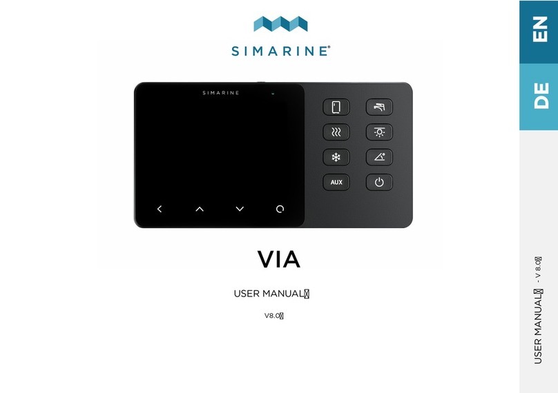
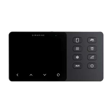
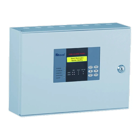
Figure 1: Control panel SCP-210
Glossary of terminology
Nereide 2
Control panel with switches and integrated PICO battery monitor. Simarine
product label SCP-210.
SiCAN
Proprietary CAN-bus based protocol for connecting distribution units to
control panels.
SiCOM
Proprietary RS485 based protocol for connecting Simarine units to PICO.
MFD
Multi-functional display.
NMEA2000
Protocol for connecting and communicating between marine oriented
devices.
N2k
Abbreviation for NMEA2000.
Table 1: List of terminology.

4
v1.4, 12th May 2023
Connecting the control panel
The control panel allows connection of up to 8 resistance sensors and 7 voltage sensors. It is
also compatible with all other Simarine devices.
Power source and power modes
The panel requires 12 V DC voltage source protected with a 2 A fuse. Maximum ratings for
the power supply voltage source are:
omin.: 6 V DC
omax.: 35 V DC
The recommended source of power:
ocontrol panel: 12 V DC from battery, either directly or through a main switch
Current ratings for typical system (single SCP-210 control panel with 1 SPU-303 distribution
unit):
-Normal operation mode: 100 –200 mA
-Low power with bilge LED active: 50 mA
-Low power with bilge LED inactive: 40 mA
“Normal mode” is the state when the control panel is turned on. All buttons are active and the
user can operate the consumers by pressing the buttons. PICO battery monitor is active and
fully functional.
“Low power mode” is a low power state when the user turns off the control panel by long
pressing the power button. In this state the buttons are disabled. If the control panel is
configured to use the integrated bilge pump functionality, the bilge pump LED indicator will
be active for 24 hours. PICO battery monitor enters sleep state, monitoring is active, but the
user cannot interface with the device.
The control panel may be configured to enable or disable the low power mode. With the lower
mode ENABLED, the device will enter low power mode when the user turns off (long hold of
power button) the panel. With the low power mode DISABLED, the control panel will fully turn
off when the user turns off the panel. This means that also PICO battery monitor will be fully
turned off.
The low power mode can be enabled/disabled by toggling the switch behind the back cover
(the cover has to be removed by undoing the bolts) as is pictured below.

5
v1.4, 12th May 2023
Figure 2: Low power mode enable/disable switch.
Simarine devices
The panel supports all other Simarine devices. It connects to them through SiCOM. The
devices can connect directly to the 2 SiCOM ports. The panel itself provides the power to the
SiCOM ports. Using a SiCOM splitter is not permitted. See figure 2 for more information.
Sensors
As previously stated, the control panel SCP-210 has 8 resistance measuring inputs and 7
voltage inputs.
Ohmmeter specification:
o8 inputs
orange: 0 –65 kΩ
oresolution: 1 Ω
oprecision: ± 3 %
Voltmeter specification:
o7 inputs
orange: 0 –70 V DC
oresolution: 1 mV
oprecision: ± 1 %
All inputs are shown on the integrated PICO and can be configured as any other sensor. See
PICO manual for more information.

6
v1.4, 12th May 2023
Figure 3: Control panel connections diagram.

7
v1.4, 12th May 2023
Connecting and switching a bilge pump
Note: This function is only available per request when ordering the Nereide 2
system!
A bilge pump can be connected to the control panel. The recommended wiring schematics is
shown on the figure below. The +12V pin is an input for the battery voltage, and the MANUAL
and AUTO pins are outputs. The AUTO pin should be connected to the floater switch and the
MANUAL pin directly to the bilge pump motor.
Figure 4: Connecting a bilge pump.
When pressing the dedicated BILGE PUMP button on the front of the control panel the
integrated relay will enable the output on the MANUAL pin. The AUTO pin output is always
enabled, unless the dedicated button is pressed. The switching is done by an internal relay
for which schematics is provided below.
Figure 5: Internal schematics of the bilge pump connector.

8
v1.4, 12th May 2023
Bilge pump status indicator
There is also a feedback system implemented for alerting the user the status of the bilge
pump connections. The status is indicated by the dedicated button showing different colours
and/or flashing. The control panel monitors the input voltage on the +12V pin and the voltage
on the MANUAL pin. By monitoring these two pins the control panel can determine when the
bilge pump has been turned on by the floater switch or any possible error states. The
descriptions are provided below.
Constant green
Normal operation, voltage on +12V detected, bilge pump not
operating.
Constant blue
The button is pressed, and the bilge pump is operating.
Flashing
green/blue
Normal operation, voltage on +12V detected, floater switch
turned ON, bilge pump operating.
Flashing
blue/red
Error state! Button pressed, voltage on MANUAL pin not
detected.
Control panel relay problem.
Bilge pump might not be operating!
Constant red
Error state! Input voltage on +12V pin not detected. Check for
blown fuse, connection to the battery or wiring issues.
Bilge pump might not be operating!
Table 2: Bilge pump status descriptions.

9
v1.4, 12th May 2023
Connecting and switching remote switches
Note: This function is only available per request when ordering the Nereide 2
system!
Up to three remote switches can be connected to the control panel. Supported remote
switches can have two types of signals for controlling. A “TOGGLE” and “SWITCH” type.
The TOGGLE type has two wires for control. A pulse on one wire closes the remote switch and
a pulse on the other closes it. An example of wiring for this type is shown on Figure 8: Toggle
signal type of remote switch.
The SWITCH type has only one wire for controlling. If this wire has 12 V DC voltage present,
the remote switch closes and if it has no voltage or is connected to ground it opens. These
two types are applicable to most remote switches available on the marine market. An example
is shown on Figure 9: Switch signal type of remote switch.
The type of remote switch is selected with the switch marked on the figure below:
Figure 6: Selecting the type of remote switch.
The control panel also has capability to detect the current state of the remote switch. This is
done by connecting the feedback signal to the FB pin on the connector. With the switch
marked on the figure below you can select the level of the feedback signal.
Selecting “L” is for a feedback signal that is driven low (connected to ground) when the remote
switch is closed. This is common on remote switches that have a LED OUTPUT instead of
FEEDBACK OUTPUT.
Selecting “H” is for a feedback signal that is driven high (12V DC) when the remote switch
closes. This can also be used in cases when the remote switch does not have a feedback
output or when the output does not have compatible signals. In this case it is possible to wire
the feedback signal from the consumer side of the remote switch main contacts as seen on
Figure 10: Feedback signal from remote switch output. If this type of wiring is used it is
important to use a fuse. The fuse can be rated for as little as 100mA or less. Fuses
with larger ratings should be avoided.
Figure 7: selecting the level of feedback signal.

10
v1.4, 12th May 2023
Figure 8: Toggle signal type of remote switch.
Figure 9: Switch signal type of remote switch.

11
v1.4, 12th May 2023
Figure 10: Feedback signal from remote switch output.
Remote switch connector pin descriptions:
+12V
Input
Voltage source input, 12V DC from battery, protected by a fuse
(recommended 1A or lookup into remote switch datasheet).
OFF
Output
If selected “SWITCH” type: constantly outputs 12V when the
dedicated button is turned OFF.
If selected “TOGGLE” type: outputs a short pulse (100 ms) when
the dedicated button turns to OFF.
ON
Output
If selected “SWITCH” type: constantly outputs 12V when the
dedicated button is turned ON.
If selected “TOGGLE” type: outputs a short pulse (100 ms) when
the dedicated button turns to ON.
FB
Input
Feedback input. Allowed voltage range 0 –15V DC. Connected to
feedback or LED outputs of remote switches.
Table 3: Remote switch connector pin descriptions.

12
v1.4, 12th May 2023
Connectors –detailed description
Below are descriptions of connectors used to connect to the control panel (cable side).
-Ohmmeter inputs (resistance sensors)
oplug - molex 39013022
opins –molex 39000038
-Voltmeter inputs:
o8 pin female Wago 769-108
-Power input:
o3 pin female Wago 769-103
-SiCAN/NMEA:
oDeviceNet 5 pin M12 female
-Remote switch:
oPluggable terminal block 4 pin female, pitch 5,08 mm,
Phoenix Contact 1792265 or similar
-Bilge pump:
oPluggable terminal block 4 pin female, Phoenix Contact 1777749
-SiCOM:
oRJ11 4 pin plug

13
v1.4, 12th May 2023
CAN and NMEA ports
Basic description and connecting
The panel connects to the distribution unit by using a proprietary CAN bus based protocol
called SiCAN. This bus uses DeviceNet 5-pin cables and T-splitters. This is the same cable as
NMEA2000 drop cable. SiCAN bus is used to connect the panel and distribution unit, which
requires at least 1 terminator for short connections (less than 3 meters) or 2 terminators at
each end for longer connections (more than 3 meters).
The SiCOM ports on the SPU-303 are inactive and provide no function. They should be left
unconnected.
Connecting to the NMEA2000 network is done by using an NMEA2000 drop cable. The NMEA
network should also be terminated as per NMEA standard.
The maximum total SiCAN bus cable length is 250 m. It is recommended to keep
the bus length as short as possible.
Figure 11: Connecting the panel to the distribution unit and NMEA2000 network.
NMEA2000 data streaming
The control panel can transmit battery and other data from the integrated PICO to the
NMEA2000 network due to the built-in NMEA2000 gateway. This works in the same way, as

14
v1.4, 12th May 2023
an SN01 NMEA2000 gateway connected to a standalone PICO. For more information look into
the SN01 user manual (simarine.net)
NMEA2000 remote switching
Note: This function is only available per request when ordering the Nereide 2
system!
In addition to transmitting data from the PICO, the NMEA2000 port allows the control panel
to receive switching commands. Other manufacturers MFD’s or other devices can be used for
remote controlling of the switch states on the control panel.
PGN
PGN Name
Receiving
Transmitting
127501
Binary Switch Bank Status
No
Yes
127502
Switch Bank Control
Yes
No
The buttons on the control panel appear as a single instance of a binary switch bank. By
default every button is switchable via the NMEA2000 network. The control panel will
periodically transmit PGN Binary Switch Bank Status with the states being the states of the
buttons on the front of the control panel. On, off and error states are transmitted.
oThe switch control and status indexes are the same and are in the range of 1 to 28.
oThe instance of the switch bank for both PGNs is 40 (decimal).
oIndexes 10 and 20 to 28 are unused.
oThe “POWER” button is not switchable via NMEA2000.
The visual representation below shows how the indexes are mapped:

15
v1.4, 12th May 2023
Figure 12: NMEA2000 switch bank indexes.

16
v1.4, 12th May 2023
DC distribution unit
The DC distribution unit (SPU-303) connects to the battery through the main switch with a
recommended 200 A fuse. The unit has 31 switch channels (relays) each connected to 1 or
more output pins. Each relay has a corresponding fuse with a rating that must be the same
or lower as the maximum allowed current through the relay.
Relay maximum allowed current:
ofor relays K1 to K31, excluding K8: max. 20 A
ofor relay K8: max 30 A.
Figure 13: Power source for the DC distribution unit.

17
v1.4, 12th May 2023
Table of connector pins and corresponding fuses
Below is a table of connectors with associated relays, fuses and output pins.

18
v1.4, 12th May 2023
Table 4: DC distribution unit output layout.

19
v1.4, 12th May 2023
Figure 14: Relays with corresponding pins.

20
v1.4, 12th May 2023
Using the control panel and distribution units
The control panel turns on by pressing the power button. To turn the panel off the power
button should be held for 1 second. When the panel turns off it first turns off all the relays on
the connected DC distribution unit. The panels without bilge pump support turn off
immediately and do not enter sleep mode.
The panels with bilge pump support will enter sleep mode when turned off. The LED for the
bilge pump will remain active for 24 hours and then the LED will be disabled to achieve even
lower power consumption. The control panel still reports the voltmeter and ohmmeter
readings to the PICO, but the switching, button functionality stays completely disabled while
in sleep mode.
The integrated PICO battery monitor turns off and on simultaneously with the panel. In the
panels with bilge pump support, it will also enter sleep mode when turned off. To wake-up
the PICO, the panel has to be turned on. All of the monitoring functions of the PICO including
alarms will remain active in sleep mode.
To turn on or off a consumer connected to the distribution unit, a short press of a button on
the control panel is needed. There are two types of buttons –toggle and momentary. A toggle
button will change the set state each time you press it. A momentary button will keep the set
state ON as long as you hold it pressed. The button glows in dim white when it is turned OFF
and bright blue when it is turned ON.
Each button can control the set state of multiple channels on the distribution unit. Usually 1
button has multiple channels assigned. A channel is a relay and fuse combination on the
distribution unit. Each channel is monitored and controlled by the control panel. Each channel
has a set state for the relay (ON or OFF), actual state of the relay (ON, OFF, manual ON,
manual OFF) and fuse state (OK or BLOWN).
Button illumination and errors
The buttons can show different colours as feedback for the set state or errors. In case of an
error the button will blink between the set state colour and red colour.
Dim white
Button set to OFF.
Constant blue
Button set to ON.
Flashing
blue/red.
Error state! Button set to ON, error on assigned channels.
Burnt fuse or stuck relay in OFF position on distribution unit.
Flashing
white/red
Error state! Button set to OFF, error on assigned channels.
Stuck relay or manually switched to ON position.
Constant red
Error state! Lost connection to channel. Check CAN
connections –loose cables or missing terminators.
This manual suits for next models
2
Table of contents
Other SIMARINE Control Panel manuals
