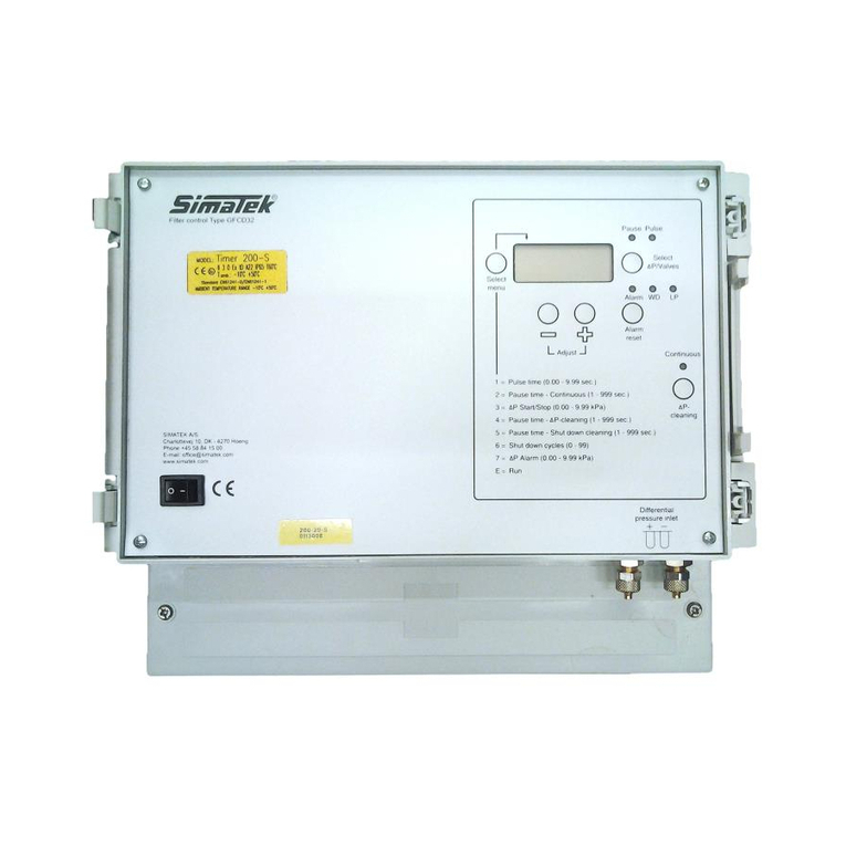
Simatek GFC 16 User manual

Manual
Control Unit GFC 16
1400003_EN/04.2017

Control Unit
GFC 16
SIMATEK A/S
www.simatek.com
Hotline: +45 4046 7525
aftersales@simatek.dk
2
Doc. No.: 1400003_EN
Rev.: -
Date: 04.2017
Index
1. Main features 3
2. Tekniske data 3
3. Installation guidelines 4
4. Preliminary checks 5
5. Electrical connections 5
6. Settings 5
7. Remote 7
8. Shut down cleaning 7
9. Troubleshooting 8
10. Fuse table 8
11. Factory settings/Program menu 9
12. Legend 10
13. General assembly Simatek GFC 16: 2-16 valves 11
14. Electric diagram - Simatek GFC 16: 2–10 valves 12
15. Electric diagram - Simatek GFC 16: 12–16 valves 13
16. Declaration of conformity 14
NOTE! Figures shown inside square brackets […] refer to positions on page 11.
CAUTION! Before use, read the instructions thoroughly to acquire sufficient knowledge of the product. For your
convenience, keep this sheet as a quick reference.
Subject to change without notice.
Note: The GFC 16 unit is to be installed by trained personnel only!

Control Unit
GFC 16
SIMATEK A/S
www.simatek.com
Hotline: +45 4046 7525
aftersales@simatek.dk
3
Doc. No.: 1400003_EN
Rev.: -
Date: 04.2017
1. Main features
The Simatek GFC 16 has been designed to guarantee the control of diaphragm valves mounted on the pulse jet dust
collector filters containing filter bags or cartridges.
The main features of the Simatek GFC 16 are:
-Manual selection of Pulse and Pause time.
-Can be operated by a remote pressure switch or PLC.
-SHUT DOWN CLEANING with selectable number of cleaning cycles.
2. Technical features
Enclosure
Grey ABS –transparent cover (option: 2 screws for transparent cover).
Grade of protection
IP65.
Dimensions
Simatek GFC 16: 4/ 8/ 12/ 16 outputs: case 213 x 185 x 113 mm.
Weight
Simatek GFC 16: approx. 2 kg.
Connections
Push in terminal blocks –with max. wire section of 2.5 mm².
Temperature
Storage: -20°C/+80°C.
Operating: -10°C/+50°C, with duty cycle 30%.
Voltage available
Input: 230 V (±10%) –50/60 Hz / Output: 115/230/24V AC, 24 V DC.
Input: 115 V (±10%) –50/60 Hz / Output: 115/24V AC, 24 V DC.
See page 5, 6.1
Special version 24V DC/24V DC
Power consumption
Without output 2.5 VA.
Output: 25 VA / AC or 20 W / DC.
Pulse time
0.01 –9.99 sec.
Pause time
1 –999 sec.
Max duty cycle
30%.
Remote control
Activated via external contact (normally open) free of power.
Shut down cleaning
1 –99 cycles. To be operated from the normally closed contact of fan remote
control switch.
Fuse
500 mA delayed 115 V / 230 V. 2 A delayed 24 V / 48 V.
The device is to be disposed of in accordance with current European regulations
The neutral of the power supply shall be connected to earth.
If this is not the case an isolation transformer is to be
installed and the neutral of the output to be earthed.
Otherwise the filter control will be damaged.

Control Unit
GFC 16
SIMATEK A/S
www.simatek.com
Hotline: +45 4046 7525
aftersales@simatek.dk
4
Doc. No.: 1400003_EN
Rev.: -
Date: 04.2017
3. Installation guidelines
Do not expose the control unit to direct sunlight in order to prevent overheating of the circuit board.
Connect the control unit to a continually powered line to allow SHUT DOWN CLEANING when the fan stops.
Protect the control unit from rain, water infiltration and humidity. Incomplete closing of the cover may
causeinfiltration which can seriously damage the circuit board.
Do not have cables entering via the upper part of the unit box.
Do not install any electronic devices on vibrating structures.
Use only cable glands with protection grade IP65 and of proper size (according to the cable used).
A disconnecting switch has to be installed on the power line before the control unit.
Do not attempt to repair the control unit –contact Simatek!
All wiring has to be carried out by a qualified electrician to prevent any risk of fire and electrical shocks.
The control unit wiring has to be performed in such a way that the different types of cables (power, relay’scontact,
valve output, 4-20 mA output) are kept separated and not passing close by the PCB.
Before opening the unit, make sure that the control unit is switched off (switch on/off [1] on 0 and wires onclamps
[4] disconnected), including connection to alarm/signal relays.
All the control unit electrical connections, including solenoid valves, have to use separate paths in respect to
theother loads.
Voltage selector jumpers have to be positioned only by skilled personnel and following the instructions.
A wrong voltage selectors jumpers positioning may cause potential danger to the personnel safety.

Control Unit
GFC 16
SIMATEK A/S
www.simatek.com
Hotline: +45 4046 7525
aftersales@simatek.dk
5
Doc. No.: 1400003_EN
Rev.: -
Date: 04.2017
4. Preliminary checks
1. Check that Simatek GFC 16 does not have power (on/off switch [1] on 0 and terminals [4] disconnected).
2. Check that the supply voltage indicated on the yellow label [22] as “IN”, corresponds to the available powersupply
(Voltage and Frequency).
3. Check that the supply voltage to valves indicated on the yellow label [22] as “OUT”, corresponds to
thevoltage/frequency as indicated on the coils.
5. Electrical connections
1. Unscrew and remove the terminals cover [20].
2. Check that Simatek GFC 16 does not have power (on/off switch [1] on 0 and terminals [4] disconnected).
3. Extract the removable terminals [2].
4. Check that the supply voltage to valves indicated on the yellow label [22] as “OUT” corresponds to the
voltage/frequency as indicated on the coils.
5. Connect the valves to the terminal blocks [2], between terminal C and the numbered outputs.
-Earthing [3] of the valves is necessary when output voltage is ≥48 V.
-NEVER connect the Common or valve output to earth [3].
-The Commons are interconnected on the printed circuit board.
-The outputs are “static” type, with “zero crossing” command, to prevent electrical disturbances.
6. Check that the valve connections are correct and isolated in regard to earthing, by measuring the isolation
between Ground [3] and Common with outputs terminal.
7. Replace the terminals cover and replace the screws [20].
6. Settings
6.1 Voltage selection
CHECK:
1. That Simatek GFC 16 does not have power (on/off switch [1] on 0 and terminals [4] disconnected).
2. That the supply voltage indicated on the yellow label [22] as “IN” corresponds to the available supply
voltage.(Voltage and Frequency).
3. That the supply voltage to valves indicated on the yellow label [22] as “OUT” corresponds to the
voltage/frequency as indicated on the coils.
If these 3 conditions are met, go to paragraph 6.2.
Otherwise, carefully follow the procedure below!
A. Supply voltage selection
1. Unscrew the two screws [21] (optional), and open the Simatek GFC 16 transparent cover.
2. Remove the 4 screws of the front panel. Lift the front panel (do not remove it as it is connected to the base of
the enclosure!).
3. Check that the supply voltage selected by jumper [5], corresponds to the one available from the supply
voltage(e.g. both 230 V).
4. Should the two voltages be different, move the jumper [5] in order to select the same supply voltage.
5. Go to point 6.1B.
B. Selection of power supply to the valves
1. Check that the supply voltage to the valves, selectable by jumpers [6] and [6A], corresponds to the supply
voltage indicated on the coils of the valves (e.g. both 230 V).
Jumper [6]: 1HV = 115 V; 2HV = 230 V; LV = 24 V
Jumper [6A]: HV = 115 V / 230 V; LV = 24 V
2. Should the two voltages be different, replace the jumpers [6] and [6A] in order to select the same supply voltage
as indicated on the coils.
Jumper [6]: 1HV = 115 V; 2HV = 230 V; LV = 24 V
Jumper [6A]: HV = 115 V / 230 V; LV = 24 V
CAUTION! Both jumpers [6] and [6A] must correspond to the same voltage!
3. Go to point 6.1C.

Control Unit
GFC 16
SIMATEK A/S
www.simatek.com
Hotline: +45 4046 7525
aftersales@simatek.dk
6
Doc. No.: 1400003_EN
Rev.: -
Date: 04.2017
C. Selection of power supply frequency to the valves (AC/DC)
1. Make sure that the output frequency to the valves, selected by jumper [8], corresponds to the value indicated on
the coils (e.g. both are set to AC).
2. Should the two frequencies be different, move the jumper [8] in order to select the same frequency as indicated
on the coils.
3. Put the front panel back in place and fasten the 4 screws.
4. Close the transparent cover by means of the two screws [21] (Optional).
Never select 115 or 230 V DC for output!
6.2 Parameters selection
Connecting the power supply [4]:
L = phase, N = neutral
On/off switch [1] on 1. The display [7] will indicate for 3 seconds the release code of Simatek GFC 16.
Once the codes disappear, the display will show letter E (run) and the number of the valve which is going to be
activated. LED OK [18] and REMOTE [35] are on.
1) Press SELECT MENU [9]:
1 will flash on display [7]:
Using keys “+/-” [10] select the No. of valves, you wish to connect.
Example: If you wish to connect 4 valves to Simatek GFC 16, select 4.
Should you skip this step of the MENU, Simatek GFC 16 will automatically
set No. of valves as if they were all connected (Simatek GFC 16:4) then 4
valves will be recognized, (Simatek GFC 16:12) then 12 valves will be
recognized.
2) Press SELECT MENU [9]:
2 will flash on display [7]:
Using keys “+/-” [10] select Pulse time (0.01 – 9.99 sec).
3) Press SELECT MENU [9]:
3 will flash on display [7]:
Using keys “+/-” [10] select Pause time (1 – 999 sec).
4) Press SELECT MENU [9]:
4 will flash on display [7]:
Using keys “+/-” [10] select No. of cycles of Shut down cleaning.
Select 0 if you do not wish to have shut down cleaning.
Pause time in Shut down cleaning is the same as the one selected at point 3).
5) Press SELECT MENU [9]:
E1 will flash on display [7] the cleaning cycle starts.
LED 1 [11] will indicate that a valve is activated.
LED 2 [12] will indicate that Simatek GFC 16 is waiting to activate the next
valve.
NOTE!
-Valves are pulsed from output No. 1 onwards.
-Check that during the first cleaning cycle every valve is activated.
-We suggest setting the Simatek GFC 16 working parameters to clean the filter at
the lowest possible frequency, thereby reducing the little dust escape arising
during jet-pulsing, achieving a longer lifetime of filterbags/cartridges and
reducing the compressed air consumption.
-Pause time should allow an efficient filter cleaning in worst conditions, but
should never be shorter than the time needed to re-pressurise the compressed-
air tank.
-While selecting parameters (in Select menu), Simatek GFC 16 will return to
normal operation if no buttons are pressed within a 5 minutes interval.

Control Unit
GFC 16
SIMATEK A/S
www.simatek.com
Hotline: +45 4046 7525
aftersales@simatek.dk
7
Doc. No.: 1400003_EN
Rev.: -
Date: 04.2017
7. Remote
NOTE!
Simatek fits the Simatek GFC 16 unit with a connection on terminals Remote [26] and Common [37].
If you wish to operate Simatek GFC 16 with a remote switch, read instructions below.
If you do not wish to take advantage of this opportunity, do not remove the connection.
To activate Remote:
1. Unscrew and remove the terminals cover [20].
2. Remove the connection from terminals Remote [26] and Common [37].
3. Bring an external no-load and normally open (NO) contact to Remote [26] and Common [37] terminals from an
external device (example: contact from DP monitor).
4. Replace and screw the terminals cover tight [20].
5. Close the contacts on the Remote [26] and Common [37] terminals in order to enable the Remote function.
6. Should you open the contact on Remote [26] and Common [37], Simatek GFC 16 will stop working, display will
show SB (stand by) and LED Remote [35] and LED Pause [12] will be off. Close the contact in order to start the
cleaning cycle again from the position it stopped.
8. Shut down cleaning
We suggest operating one or more cycles of Shut down cleaning at the end of each working session in order to remove
the residual dust of the filter. Shut down cleaning is started each time the fan is switched off.
In order to activate Shut down cleaning:
1. Select the number of cycles in Shut down cleaning (see 6.2).
2. Unscrew and remove the terminals cover [20].
3. Bring an external no-load and normally closed (NC) contact to terminals Fan [36] and Common [37] from the fan
switch.
4. Replace the terminals cover [20] and tighten the screws.
5. Close the contact on the Fan [36] and Common [37] terminals in order to start Shut down cleaning each time the
fan is switched off. The present cleaning cycle will be considered as the first cycle of Shut down cleaning.
NOTE Should you have selected 0 at step 4) of point 6.2, Simatek GFC 16 will stop working as soon as the contact on
terminals Fan [36] and Common [37] are closed.
-LED Shut down [33] will flash during Shut down cleaning.
6. At the end of Shut down cleaning LED Shut down [33] will remain on and the display will show E1.
Switch the fan on in order to start cleaning cycle again and to switch LED Shut down [33] off.

Control Unit
GFC 16
SIMATEK A/S
www.simatek.com
Hotline: +45 4046 7525
aftersales@simatek.dk
8
Doc. No.: 1400003_EN
Rev.: -
Date: 04.2017
9. Troubleshooting
Problem
Probable cause
Solution
Display is blank and all
LEDs are off.
No power supply.
.
Check the connections of the power
supply terminals [4].
Display shows Sb.
The connection on terminals Remote and
Common [26] is not connected.
Check the connection.
Check fuse F1 [31].
Replace the fuse (see chapter 10).
Some valves are ignored.
.
Wrong electrical connections between Simatek
GFC 16 and coils.
Check connections [2].
Coils are interrupted.
Check coils continuity.
Display shows the pulsing
sequence but valves are not
functioning.
The secondary of the transformer is
interrupted.
Contact Simatek.
Power circuit is damaged.
Contact Simatek.
Supply voltage to valves is different from
voltage indicated on the coils.
Check or re-select supply voltage.
(See chapter 6.1).
Wrong connection between
Simatek GFC 16 and valves.
Check connections [2].
LED OK [18] is off.
Microprocessor failure.
Contact Simatek.
10. Fuse table
Name
Size
Value
Type
No. on drawing
Description
F3
5 x 20
500 mA
T
[23]
115 V/230 V Main supply fuse
F3
5 x 20
2 A
T
[23]
24 V/48 V Main supply fuse
F1
5 x 20
1,6 A
T
[31]
Output 24 V and fan –Rem
F2
5 x 20
630 mA
T
[32]
+5 V internal power supply
In case of replacement you must respect the values above. .

Control Unit
GFC 16
SIMATEK A/S
www.simatek.com
Hotline: +45 4046 7525
aftersales@simatek.dk
9
Doc. No.: 1400003_EN
Rev.: -
Date: 04.2017
11. Factory settings/Program menu
11.1 Pulse time
Simatek recommends a pulse time of 0.2 sec.
11.2 Pause time
By continuous cleaning, the pause time is calculated from a total
cleaning time for the filter of 180 sec.
See recommended pause time by continuous cleaning for the
current filter type. However, the pause time must correspond to
the compressor capacity (compressor shall be able to fill the
compressed-air tank between each pulse).
11.3 Shutdown cleaning cycles
Bag cleaning will continue during the set number of cycles (first
valve to last valve) after connection between Fan [36] and
Common [37], (fan stopped).
Any equipment for removal of the separated dust should run
during shut down cleaning.
Simatek recommends 2-3 cycles, as the current cycle is
regarded as the first shut down cycle. Therefore the first cycle
will not necessarily be a full cycle.
Recommended pause times for SimPact® 4T/4T-
R filters

Control Unit
GFC 16
SIMATEK A/S
www.simatek.com
Hotline: +45 4046 7525
aftersales@simatek.dk
10
Doc. No.: 1400003_EN
Rev.: -
Date: 04.2017
12. Legend
[1] On/off-switch
[2] Push in valves terminals
[3] Valves earthing
[4] Power supply terminals
[5] Jumper for inlet supply voltage selection
[6] Jumper for voltage selection to valves
[6A] Jumper for voltage selection to valves
[7] Display
[8] Jumper for the frequency selection to valves (AC/DC)
[9] Push button Select menu
[10] Push buttons +/-
[11] LED Pulse
[12] LED Pause
[18] LED OK
[20] Terminals cover
[21] Transparent cover fixing screws (optional)
[22] Yellow label indicating IN/OUT voltage-frequency
[23] Main fuse
[25] Product code and serial number
[26] Remote terminal
[31] Output fuse 24 V and Fan –Rem
[32] +5 V internal power supply fuse
[33] LED Shut down
[35] LED Remote
[36] FAN terminal
[37] Common-terminal

Control Unit
GFC 16
SIMATEK A/S
www.simatek.com
Hotline: +45 4046 7525
aftersales@simatek.dk
11
Doc. No.: 1400003_EN
Rev.: -
Date: 04.2017
13. General assembly Simatek GFC 16: 2-16 valves

Control Unit
GFC 16
SIMATEK A/S
www.simatek.com
Hotline: +45 4046 7525
aftersales@simatek.dk
12
Doc. No.: 1400003_EN
Rev.: -
Date: 04.2017
14. Electric diagram - Simatek GFC 16: 2–10 valves

Control Unit
GFC 16
SIMATEK A/S
www.simatek.com
Hotline: +45 4046 7525
aftersales@simatek.dk
13
Doc. No.: 1400003_EN
Rev.: -
Date: 04.2017
15. Electric diagram - Simatek GFC 16: 12–16 valves

Control Unit
GFC 16
SIMATEK A/S
www.simatek.com
Hotline: +45 4046 7525
aftersales@simatek.dk
14
Doc. No.: 1400003_EN
Rev.: -
Date: 04.2017
16. Declaration of conformity
Table of contents
Other Simatek Control Unit manuals
Popular Control Unit manuals by other brands
RWC
RWC Heatguard TMV3-8 Installation and maintenance instructions

Zehnder Pumpen
Zehnder Pumpen ENS 1.1 operating manual

NCR
NCR K150 Programming guide

HWH
HWH 625 Series Operator's manual

Astronautics Corporation of America
Astronautics Corporation of America AFS6360 user manual
SMA
SMA MD.IO-40 installation manual

Mitsubishi Electric
Mitsubishi Electric GT1020-LBD General description

CLA-VAL
CLA-VAL 90-01 Technical documentation
Metso
Metso E2 Series Installation maintenance and operating instructions
JPEG Camera
JPEG Camera SC03MPE user manual
Watts
Watts WFC-03 HCM RF 230 Quick installation guide
Viega
Viega 8127.3 Instructions for use
