Simatek GFCD 32 User manual

Manual
Control Unit
GFCD 32
1400001_EN/05.2017

Control Unit
GFCD 32
SIMATEK A/S
www.simatek.com
Hotline: +45 4046 7525
aftersales@simatek.dk
2
Doc. No.: 1400001_
EN
Rev.:
-
Date: 05.2017
Index
1. Main features 3
2. Technical features 3
3. Installation guidelines 4
4. Preliminary checks 5
5. Electrical connections 5
6. Filter taps 5
7. Settings 6
8. Shut down cleaning 8
9. Codes and alarms 9
10. ΔP/Valves button 9
11. Low pressure function (or Stand-by) 10
12. ΔP value playback (optional) 10
13. Troubleshooting 12
14. Fuse table 12
15. Factory settings/Program menu 13
16. Legend 14
17. Simatek GFCD 32 4-20: General assembly 15
18. Electric diagram for Simatek GFCD 32: 20 valves 16
19. Declaration of Conformity 17
NOTE! Figures shown inside square brackets […] refer to positions on drawing page 17.
ATTENTION! Before use, read the instructions thoroughly to acquire sufficient knowledge of the product. For your
convenience, keep this sheet as a quick reference.
Subject to change without notice.
The GFCD 32 unit is to be installed by trained personnel only

Control Unit
GFCD 32
SIMATEK A/S
www.simatek.com
Hotline: +45 4046 7525
aftersales@simatek.dk
3
Doc. No.: 1400001_
EN
Rev.:
-
Date: 05.2017
1. Main features
The Simatek GFCD 32 completely controls the diaphragm valves, on the dust collector filters, with pneumatic cleaning
procedures (pulse-jet). The main features of the Simatek GFCD 32 are:
– Automatic regulation of cleaning, according to the level of filter clogging (ΔP).
– Operating mode selection (MANUAL or AUTOMATIC).
– Automatic identification of connected valves (disconnected outlets are automatically skipped).
– Shut down cleaning, with programmable number of cycles.
– Low Pressure or Stand-by function.
– Remote commutation of position (MANUAL or AUTOMATIC).
– ΔP value playback (optional).
2. Technical features
Enclosure
Grey ABS – transparent cover
Grade of protection
IP65
Dimensions
Simatek GFCD 32:20 (from 4 to 20 outputs): case 296 x 256 x 118 mm
Weight
Simatek GFCD 32: approx. 3.3 kg
Connections
Push in plugs – with max. wire section of 2.5 mm²
Temperature
Storage: -20° C/+80° C. Working: -10° C/+50° C
Voltage available
Input: 230 V (±10%) – 50/60 Hz / Output: 115/230/24V AC, 24 V DC.
Input: 115 V (±10%) – 50/60 Hz / Output: 115/24V AC, 24 V DC.
See page 6, 7.1
Special version 24V DC/24V DC
Power consumption
Without output 2.5 VA .
Output: max 25 VA / AC or 20 W / DC
Max pressure
75 kPa
Relay
2 A–250 V AC
Pulse time
0.01–9.99 sec
Manual pause time
1–999 sec
Automatic Pause Time
1–999 sec
Shut d.c. Pause Time
1–99 sec
Max duty cycle
30 %
Set ΔP
0.01–9.99 kPa
Set ΔP alarm
0.01–9.99 kPa
Shut down cleaning
0–99 times
Low P. or stand-by
To be operated from a non-powered external contact (normally open)
Fuses
1 A delayed with 115-230V supply
2 A delayed with 24-48V AC and 24 V DC supply
The device is to be disposed of in accordance with current European regulations
The neutral of the power supply shall be connected to earth.
If this is not the case an isolation transformer is to be
installed and the neutral of the output to be earthed.
Otherwise the filter control will be damaged.

Control Unit
GFCD 32
SIMATEK A/S
www.simatek.com
Hotline: +45 4046 7525
aftersales@simatek.dk
4
Doc. No.: 1400001_
EN
Rev.:
-
Date: 05.2017
3. Installation guidelines
•Do not expose the control unit to direct sunlight in order to prevent overheating of the circuit board.
•Connect the control unit to a continually powered line to allow SHUT DOWN CLEANING when the fan stops and
to have maximum precision in the ΔP measurements.
•Protect the control unit from rain, water infiltration and humidity. Incomplete closing of the cover may cause
infiltration which can seriously damage the circuit board.
•Do not have cables entering via the upper part of the Control unit box.
•Do not install any electronic devices on vibrating structures.
•Use only cable glands with protection grade IP65 and of proper size (according to the cable used).
•A disconnecting switch has to be installed on the power line before the control unit.
•Do not attempt to repair the control unit – contact Simatek!
•All wiring has to be carried out by a qualified electrician to prevent any risk of fire and electrical shocks.
•The control unit wiring has to be performed in such a way that the different types of cables, (power, relay’s
contact, valve output, 4-20 mA output) are kept separated and not passing close by the PCB.
•Before opening the unit, make sure that the control unit is switched off (switch on/off [1] on 0 and wires on
clamps [4] disconnected), including connection to alarm/signal relays.
•All the control unit electrical connections, including solenoid valves, have to use separate paths in respect to the
other loads.
•Voltage selector’s jumpers have to be positioned only by skilled personnel and following the instructions.
•A wrong voltage selectors jumpers positioning may cause potential danger to the personnel safety.

Control Unit
GFCD 32
SIMATEK A/S
www.simatek.com
Hotline: +45 4046 7525
aftersales@simatek.dk
5
Doc. No.: 1400001_
EN
Rev.:
-
Date: 05.2017
4. Preliminary checks
1. Check that the Simatek GFCD 32 does not have power (on/off switch [1] on 0 and terminals [4] disconnected).
2. Check that the supply voltage, indicated on the yellow label [22] as “IN” corresponds to the available power
supply (Voltage and Frequency.)
3. Check that the supply voltage to valves, indicated on the yellow label [22] as “OUT” corresponds to the
voltage/frequency as indicated on the coils.
5. Electrical connections
1. Unscrew and remove the terminals cover [20].
2. Check that Simatek GFC 16 does not have power (on/off switch [1] on 0 and terminals [4] disconnected).
3. Extract the removable terminals [2].
4. Check that the supply voltage to valves indicated on the yellow label [22] as “OUT” corresponds to the
voltage/frequency as indicated on the coils.
5. Connect the valves to the terminal blocks [2], between terminal C and the numbered outputs.
6. Earthing [3] of the valves is necessary when output voltage is ≥48 V.
7. NEVER connect the Common or valve output to earth [3].
8. The Commons are interconnected on the printed circuit board.
9. The outputs are “static” type, with “zero crossing” command, to prevent electrical disturbances.
10. Check that the valve connections are correct and isolated in regard to earthing, by measuring the isolation
between Ground [3] and Common with outputs terminal.
11. Put the extractable terminals back in place.
12. Replace the terminals cover and replace the screws [20].
6. Filter taps
It is very important that dust and liquid are not allowed to enter into the hose couplings, as this will damage the
instrument. Any dust clogging in the hose connections may also result in indication errors, so protection by a
filter element is recommended.
For documentation regarding these DP filters, please see documentation for the DP filter.

Control Unit
GFCD 32
SIMATEK A/S
www.simatek.com
Hotline: +45 4046 7525
aftersales@simatek.dk
6
Doc. No.: 1400001_
EN
Rev.:
-
Date: 05.2017
7. Settings
7.1 Voltage selection
CHECK:
1. That the Simatek GFCD 32 does not have power (switch on/off [1] on 0 and terminals [4] disconnected).
2. That the supply voltage, indicated on the yellow label [22] as “IN” corresponds to the available supply voltage
(Voltage and Frequency).
3. That the supply voltage to valves, indicated on the yellow label [22] as “OUT” corresponds to the
voltage/frequency as indicated on the coils.
If these 3 conditions are met, go to the paragraph 7.2.
Otherwise, carefully follow the procedure below!
A. Supply voltage selection
1. Unscrew the 2 screws [21] (optional) and open the Simatek GFCD 32 transparent cover.
2. Remove the 4 screws of the front panel. Lift the front panel (do not remove it, as it is connected to the base of
the enclosure!).
3. Check that the supply voltage, selectable by jumpers [5], corresponds to the one available from the supply
voltage (e.g. both are set to 230 V).
4. Should the two voltages be different, move the jumpers [5] in order to select the same supply voltage.
5. Go to point 7.1B.
B. Selection of power supply to the valves
1. Check that the supply voltage to the valves selectable by jumpers [6] and [6A] corresponds to the supply
voltage indicated on the coils of the valves (e.g. both are set to 24 V).
2. Should the two voltages be different, move the jumpers [6] and [6A] in order to select the same supply voltage
as indicated on the coils.
CAUTION!Both jumpers [6] and [6A] must correspond to the same voltage!
3. Go to point 7.1C.
C. Selection of power supply frequency to the valves (AC/DC)
1. Make sure that the output frequency to the valves, selectable by jumpers [8], corresponds to the value
indicated on the coils (e.g. both are set to AC).
2. Should the two frequencies be different, move the jumpers [8] in order to select the same frequency as
indicated on the coils
3. Put the front panel back in place and fasten the 4 screws.
4. Close the transparent cover by means of the two screws [21] (optional).
Never select 115 or 230 V DC for output!

Control Unit
GFCD 32
SIMATEK A/S
www.simatek.com
Hotline: +45 4046 7525
aftersales@simatek.dk
7
Doc. No.: 1400001_
EN
Rev.:
-
Date: 05.2017
7.2 Parameters selection
Check that all electrical connections have been done as described in Paragraph 5.
Switch on/off [1] on 1. On the display [7] appears, for a few seconds the Simatek GFCD 32 identification code.
Immediately after, on the display appears the value of the filter ΔP. If the LED OK [18] and Pause [12] turn on and the
LED Continuous [30] flashes, the Simatek GFCD 32 is in Manual Mode. If only the LED OK [18] turns on, the Simatek
GFCD 32 is in Automatic Mode.
Choose between Manual or Automatic Mode, with Automatic button [16]. In Manual Mode the LED Manual [30]
flashes; in Automatic Mode it is off.
ATTENTION! When the fan stops, the display [7] must indicate a filter ΔP value of 0 kPa. Otherwise, use the
regulation [15] to reset the indication at 0.
1) Press SELECT MENU [9]:
The No. 1 will flash on the display [7]:
Using the +/– buttons [10] select the Pulse Time (0.01-9.99 sec).
2) Press SELECT MENU [9]:
The No. 2 will flash on the display [7]:
Using the +/– buttons [10] select the Manual Pause Time (1-999 sec).
3) Press SELECT MENU [9]:
The No. 3 will flash on the display [7]:
Using the +/– [10] buttons select the Set Delta-P (0.01-9.99 kPa). The cleaning
starts every time that the filter ΔP exceeds the Set Delta-P (+0.05 kPa). The
cleaning stops every time that the filter ΔP goes below the Set Delta-P.
4) Press SELECT MENU [9]:
The No. 4 will flash on the display [7]:
Using the keys +/– buttons [10] select the Automatic Pause Time. (1-999 sec)
5) Press SELECT MENU [9]:
The No. 5 will flash on the display [7]:
Using the keys +/– [10] buttons select the Pause in After Cleaning Cycle (1-99
sec).
– The Shut down cleaning automatically starts when the filter ΔP goes below 0.10
kPa.
6) Press SELECT MENU [9]:
The No. 6 will flash on the display [7]:
Using the keys +/– buttons [10] select the No. of Cycles of Shut down cleaning (0-
99 times). (Select 0 to exclude the After Cleaning Cycle) The After Cleaning Cycle
automatically starts when the filter ΔP goes below 0.10 kPa.
7) Press SELECT MENU [9]:
The No. 7 will flash on the display [7]:
Using the keys +/– buttons [10] select the Set Delta-P Alarm (0.01-9.99 kPa).
When the filter ΔP exceeds the Set Delta-P Alarm, you are in the presence of
alarm.
8) Press SELECT MENU [9]:
on the display [7] appears P000: the cycle starts.
LED PULSE [11] will indicate that a valve is activated.
LED PAUSE [12] will indicate that Simatek GFCD 32 is waiting to activate the next
valve.
NOTE!
⋅The valves are activated from outlet No. 1.
⋅The Simatek GFCD 32 automatically skips any disconnected outlets. The relative numbers run, in rapid
succession, on the display [7]. If there are no valves connected, the display will show the numbers of all
outlets.
⋅Check that during the first cleaning cycle none of the connected valves are skipped.
⋅We suggest setting Simatek GFCD 32 working parameters to clean the filter at the lowest possible frequency,
thereby reducing the little dust escape arising during jet-pulsing, achieving a longer lifetime of filter
bags/cartridges and reducing the compressed air consumption.
⋅Pause Time should allow an efficient filter cleaning in worst conditions, but should never be shorter than the
time needed to re-pressurise the compressed-air tank.
⋅Press the Delta-P/Valves button [14] to return in run from every step of Select menu. To change a parameter
value immediately returning in run: a) enter Select Menu, until the step of the desired parameter; b) change its
value; c) press Select Menu; d) press Delta-P/Valves.

Control Unit
GFCD 32
SIMATEK A/S
www.simatek.com
Hotline: +45 4046 7525
aftersales@simatek.dk
8
Doc. No.: 1400001_
EN
Rev.:
-
Date: 05.2017
⋅While selecting parameters (in Select menu), Simatek GFCD 32 will return to normal operation if no buttons are
pressed within a 5 minute interval
7.3 Manual and automatic mode operation
NOTE!
Select the shortest Pulse Time possible, between all those compatible with maximum obtainable particle separation.
This is valid both in Manual and Automatic Mode.
•Ideal time for “bag” filters: between 100 ms and 400 ms.
•Ideal time for “standard cartridge” filters: between 500 ms and 1 second.
•Ideal time for “rotating nozzle cartridge” filters: between 1 sec and 4 seconds.
7.3.1 Manual mode operation
In Manual Mode, the Simatek GFCD 32 commands the valves with fixed Pause Time. The cleaning is not dependent on
the level of the clogging of the filter bags. The Manual Mode is to be used during the start-up phase only.
When the Simatek GFCD 32 is in Manual Mode, the LED Manual [30] flashes.
In Manual Mode, the Pause Time depends on selected Manual Pause Time.
7.3.2 Automatic mode operation
In Automatic Mode, the cleaning is automatically adapted to the level of the filter bag clogging. The cleaning starts
when the filter ΔP exceeds the value of selected Set Delta-P (see 7.2). The Set Delta-P to select depends on the
structural characteristics and wear and tear of the filter and on the type of process.
When the Simatek GFCD 32 is in Automatic Mode, the LED Manual [30] is off.
In Automatic Mode, the Pause Time depends on the selected Automatic Pause Time.
7.3.3 Remote switching
It is possible to pass from Automatic Mode to Manual Mode (and vice versa) closing a remote contact. See below:
1. Unscrew and remove the terminals cover [20].
2. Connect to terminals A.M and Ground [26] an external contact free of power and normally open (NO).
3. Replace the terminals cover [20] and tighten the screws.
4. When the Simatek GFCD 32 is in Automatic Mode and you desire to pass in Manual Mode, close the remote
contact on terminals A.M and Ground [26].
5. To return in Automatic Mode, open the remote contact on terminals A.M and Ground [26].
8. Shut down cleaning
After every utilization, it is useful to carry out one or more cycles of Shut down cleaning, to free the filtering elements
of residual dust. Shut down cleaning starts when the ΔP goes below 0.10 kPa.
CAUTION:
Shut down cleaning only starts if the Simatek GFCD 32 is in Automatic mode!
In order to activate Shut down cleaning:
1. Check that the unit is in Automatic mode.
2. Select the Number of Cycles of Shut down cleaning (see 7.2). (Select 0 to exclude the Shut down cleaning).
3. Set the Pause Time in Pause in After Cleaning Cycle. (see 7.2).
4. The Shut down cleaning starts when the ΔP goes below 0.10 kPa. On the display [7] flashes the letter P. Shut
down cleaning does not start from the valve no. 1, but completes the current cycle, counting it as the first cycle
of Shut down cleaning. During Shut down cleaning, if the filter ΔP exceeds 0.15 kPa, the cleaning stops.
5. When Shut down cleaning finishes, on the display [7] appears End.

Control Unit
GFCD 32
SIMATEK A/S
www.simatek.com
Hotline: +45 4046 7525
aftersales@simatek.dk
9
Doc. No.: 1400001_
EN
Rev.:
-
Date: 05.2017
9. Codes and alarms
9.1 Leds
1) LED MANUAL [30]:
Flashes if the Simatek GFCD 32 is in Manual mode. It’s off if the Simatek GFCD 32 is in
Automatic mode.
2) LED PULSE [11]:
Is on when a valve is firing.
3) LED PAUSE [12]:
Is on between the firing of one valve and another.
4) LED L. PRESS. [15]:
Flashes when the Simatek GFCD 32 is in low-pressure.
9.2 LED OK
Incidental damages of the microprocessor are shown by the turning off of the LED OK [18]. This problem cannot be
resolved by the customer: Refer problem directly to Simatek.
To have remote signal LED OK connect the relay’s terminals WD on contacts C. N.O.
9.3 Code “P---” on the display
On the display [7] appears “P–––” if the filter ΔP goes below –0.14 kPa. If this is the case:
Check that the filtered pressure taps are connected to the pressure nipples [13] see chapter 6.
If the problem persists:
disconnect the connection pipes between the pressure filtered taps and pressure nipples [13]
use the regulation trim2 on cpu to reset the indication at 0 kPa.
reconnect [13] the connection pipes between the pressure filtered taps and pressure nipples [13].
9.4 LED alarm
The LED Alarm [17] switches on if the ΔP inside the filter exceed the ΔP Alarm selected, or if there is a short circuit on
one or more outputs.
If the LED Alarm [17] is on, Press “+” [10]:
a) If on the display [7] appears the code PPP1, the filter ΔP exceeded the selected ΔP Alarm.
Operate as follows:
1. Stabilise the filter ΔP.
2. Press “-” to return to run mode.
3. Press Reset [19): the alarm disconnects.
b) If on the display [7] appears the letter A followed by a number, the valve countermarked with that number is
in short circuit.
Operate as follows:
1. Continue to press the button “+” [10], to read on the display the number of the faulty outputs. Attention: the
alarm intervention excludes the faulty valve, which is in short circuit.
2. Repair the damages.
3. Press “–” to return in run.
4. Press Reset [19]: the alarm disconnects. The command of defective valves restarts
To have remote signal LED Alarm connect the relay’s terminals ALL on the contacts C. N.C.
10. ΔP/Valves button
On the display [7], the Simatek GFCD 32 shows the filter ΔP. Press Delta-P/Valves [14] to pass from filter ΔP
indication to active valve indication (and vice versa). When you turn on the Simatek GFCD 32, on the display
automatically is visualised the filter ΔP.

Control Unit
GFCD 32
SIMATEK A/S
www.simatek.com
Hotline: +45 4046 7525
aftersales@simatek.dk
10
Doc. No.: 1400001_
EN
Rev.:
-
Date: 05.2017
11. Low pressure function (or Stand-by)
It is possible to put the Simatek GFCD 32 in Low Pressure (or Stand-by) remotely. When the Simatek GFCD 32 is in
Stand-by, all its functions are blocked.
To activate the function:
1. Unscrew and remove the terminal cover [20].
2. Pull out the extractable terminal [27].
3. Connect to S.B and Ground terminals [27] an external contact free of power and normally open (NO).
4. Put back the extractable terminal [27].
5. Replace the terminals cover [20] and tighten the screws.
6. Close the contact on S.B and Ground terminals [27] to put the Simatek GFCD 32 in Stand-by. The LED Low
Pressure [15] flashes.
7. Open the contact on S.B and Ground terminals [27] to restart the cycle. The Low Pressure [15] turns off.
12. ΔP value playback (optional)
With the assembled board it is possible to broadcast to distance, on other unit, the ΔP value that is showed on Simatek
GFCD 32 display [7]. Connect to the terminals 4-20 mA POS and 4-20 mA NEG see page 10.
12.1 4-20 mA connection
ATTENTION! The output 4-20 mA is passive: connect it to an external power supply!
1. Unscrew and open the terminals cover .
2. Pull out the extractable terminals from terminal and .
3. Connect to 4-20 mA POS the positive terminal (+) of the remote unit.
4. Connect to 4-20 mA NEG terminal the negative (-) terminal of a stabilized power supply (5-30 V DC).
5. Insert a Resistance on the connections between negative terminal (–) of remote unit and positive terminal (+)
of the Stabilised power supply.
•If the power supply is lower than 15 V DC, don’t insert any resistance.
•If the power supply is between 15 and 24 V DC, insert a resistance of 470 Ω ½ W (*).
•If the power supply is higher than a 24 V DC, insert a resistance of 1000 Ω 1 W (*).
•(*) Indicative values! Make practical tests, to adapt it to your situation!
6. Use a shielded cable for the connections.
7. Close and screw the terminals cover .
3
3
1 2
1
2

Control Unit
GFCD 32
SIMATEK A/S
www.simatek.com
Hotline: +45 4046 7525
aftersales@simatek.dk
11
Doc. No.: 1400001_
EN
Rev.:
-
Date: 05.2017
12.2 4-20 mA assembled card
Check that the Simatek GFCD 32 is not powered: switch on/off
on 0 and terminals disconnected.
Unscrew the 2 screws , and open the transparent cover of the
Simatek GFCD 32.
Unscrew the 4 screws and lift the front panel (do not remove
it!).
12.3 Full-scale 4-20 mA setting
1. Turn on the Simatek GFCD 32 (switch on/off on 1) keeping pressed the Reset key until code “PPSS”
appears on the display. Release Reset key: on the display code “A0” appears.
2. Press “–” until compose on the display the number “A879”.
3. Press Select menu: on the display appears the letter C and the number of outlets of the Simatek GFCD 32.
(Example: in case of a Simatek GFCD 32:32, appears “C 32” on the display).
4. Press Select menu: on the display appears “P 0”.
5. Leave “P 0” if you want a full scale value of 99.9 kPa.
6. With “+” select “P 1” if you want the full-scale value of 1.00 kPa.
7. With “+” select “P 2” if you want the full-scale value of 2.00 kPa.
8. With “+” select “P 3” if you want the full-scale value of 3.00 kPa.
9. With “+” select “P 4” if you want the full-scale value of 4.00 kPa.
10. With “+” select “P 5” if you want the full-scale value of 5.00 kPa.
11. Press Select menu: on the display appears the ΔP into the filter.
12. Press Select menu the cycle restarts.
5
6
7
8
5

Control Unit
GFCD 32
SIMATEK A/S
www.simatek.com
Hotline: +45 4046 7525
aftersales@simatek.dk
12
Doc. No.: 1400001_
EN
Rev.:
-
Date: 05.2017
13. Troubleshooting
Problem
Probable cause
Solution
Display is blank and all LED are off.
No power supply.
Check the tightening of the terminal
[4] and the selection of the power
supply voltage [5]. Check main fuse
[23].
Power supply is OK, but display is
blank and all LED are off.
Fuse [32] is broken.
Replace the fuse (see fuse table).
External contacts for stand-by and
auto/man are not working.
Fuse [31] is broken.
Replace the fuse (see fuse table).
On the display rapidly run the
numbers of all outputs.
No outputs connected.
Check the connections [2] and [3].
Some valves are skipped.
The connection between Simatek
GFCD 32 and solenoid valves is
wrong.
Check the connections [2] and [3].
The solenoid valves are
disconnected.
Check the continuity of the solenoid
valves.
Display shows the pulsing sequence
but valves are not functioning.
The secondary of the transformer is
disconnected.
Refer to Simatek.
Faulty main board.
Refer to Simatek.
Power supply to the valves is
different from voltages indicated on
the coils.
Move the two jumpers [6] on the
position selecting a voltage equal to
the one indicated on the coils.
The LED OK [18] is off
Microprocessor failure.
Refer to Simatek.
The LED ALARM [17] is on.
If pressing “+” [10] button, on the
display appears PPP1, the filter ΔP
exceeded the ΔP-ALARM.
Operate as in chapter 9.4, point a).
If pressing “+” [10] button, on the
display appears “A” and the number
of a valve, that valve is in short
circuit.
Operate as in chapter 9.4, point a).
On the display appears the indication
“P---”.
The filter ΔP descended below -0.14
kPa.
Operate as in chapter 9.3.
IMPORTANT NOTE:
If you use the Simatek GFCD 32 with power supply at 24 V DC, check that it isn’t lower than 24 V and the power is
suitable at connected load.
14. Fuse table
Dimension
Value
Type
No on drawing
Description
5 x 20
1A
T
[23]
Main fuse with 115/230 V supply
5 x 20
2A
T
[23]
Main fuse with 24/48 V supply
5 x 20
200 mA
T
[31]
External contacts supply
5 x 20
630 mA
T
[32]
Internal +5 V supply (Micro, display)
In case of replacement, you must respect the values above.
Control Unit
GFCD 32
SIMATEK A/S
www.simatek.com
Hotline: +45 4046 7525
aftersales@simatek.dk
13
Doc. No.: 1400001_
EN
Rev.:
-
Date: 05.2017
15. Factory settings/Program menu
15.1 Pulse time
Simatek recommends a pulse time of 0.2 sec.
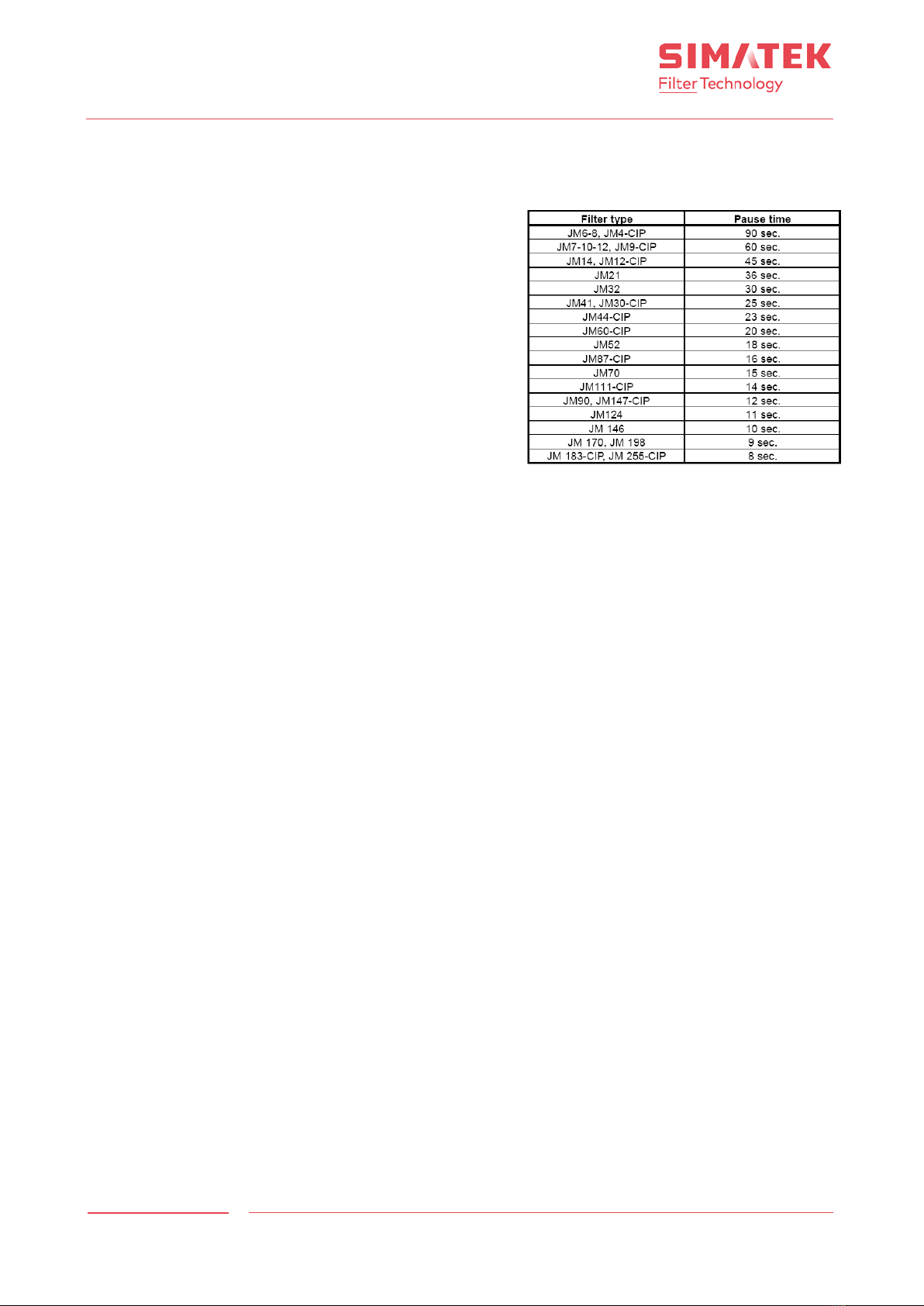
15.2 Pause time – Continuous
By continuous cleaning, the pause time is calculated from a
total cleaning time for the filter of 180 sec.
See recommended pause time by continuous cleaning for the
current filter type.
15.3 ΔP Start/stop
Each time the differential pressure in the filter exceeds the set
Value, bag cleaning starts. Bag cleaning stops, when the ΔP
drops below the set value.
ΔP Start/stop is set in Kilopascal (1 kPa = 100 mm WG).
15.4 Pause time – ΔP-Cleaning
By ΔP-Cleaning, the pause time should be set to a very low
value, as the control itself regulates how often the filter is
cleaned.
However, the pause time must correspond to the compressor
capacity to ensure that the compressed air is admitted at full
pressure during the whole cleaning sequence.
See Simatek’s filter manual regarding compressed air consumption.
15.5 Pause time – Shutdown cleaning
The pause time during shutdown cleaning may be set as required according to the properties of the dust in question,
however, the pause time must be correspond to the compressor capacity.
15.6 Shutdown cycles
Bag cleaning will continue during the set number of cycles (first valve to last valve) after the ΔP in the filter has
dropped below 0.10 kPa (the fan is off).
Any equipment for removal of the separated dust should run during shutdown cleaning.
Simatek recommends 2-3 cycles, as the current cycle is regarded as the first shutdown cycle. Therefore the first cycle
will not necessarily be a full cycle.
Shutdown cleaning only works during ΔP-cleaning. If the ΔP in the filter exceeds 0.10 kPa during shutdown cleaning,
the function will be interrupted, and ordinary bag cleaning will start.
15.7 ΔP Alarm
Each time the differential pressure in the filter exceeds the set value, an alarm is given. If required, the signal may be
led to e.g. a control room.
ΔP Alarm is set in kPa.
Recommended pause times for SimPact®4T/4T-R
filters

Control Unit
GFCD 32
SIMATEK A/S
www.simatek.com
Hotline: +45 4046 7525
aftersales@simatek.dk
14
Doc. No.: 1400001_
EN
Rev.:
-
Date: 05.2017
16. Legend
[1] On/off switch
[2] Extractable terminals (outlets and commons)
[3] Ground terminals for outlets
[4] Power supply terminals
[5] Jumper for inlet supply voltage selection
[6] Jumper for voltage selection to valves
[7] Display
[8] Jumper for the frequency selection to valves (AC/DC)
[9] Select menu button
[10] -/+ buttons
[11] LED Pulse
[12] LED Pause
[13] Inlet pressure nozzle
[14] Select ΔP/Valves button
[15] LED LP (Low pressure)
[16] Automatic/Manual mode button (ΔP-Cleaning)
[17] LED Alarm
[18] LED OK
[19] Alarm reset button
[20] Terminals cover
[21] Transparent cover fixing screws (optional)
[22] Yellow label indicating IN/OUT voltage/frequency
[23] Main fuse
[24] Relay ALL and relay WD terminals
[25] Product code and registration number
[26] Terminals for remote changing of the Mode
[27] Low pressure or Stand-by terminals
[28] 4-20 mA positive terminal
[29] 4-20 mA negative terminal
[30] LED Continuous
[31] Fuse external contacts supply
[32] Fuse internal +5 V supply (micro, display)

Control Unit
GFCD 32
SIMATEK A/S
www.simatek.com
Hotline: +45 4046 7525
aftersales@simatek.dk
15
Doc. No.: 1400001_
EN
Rev.:
-
Date: 05.2017
17. Simatek GFCD 32 4-20: General assembly

Control Unit
GFCD 32
SIMATEK A/S
www.simatek.com
Hotline: +45 4046 7525
aftersales@simatek.dk
16
Doc. No.: 1400001_
EN
Rev.:
-
Date: 05.2017
18. Electric diagram for Simatek GFCD 32: 20 valves

Control Unit
GFCD 32
SIMATEK A/S
www.simatek.com
Hotline: +45 4046 7525
aftersales@simatek.dk
17
Doc. No.: 1400001_
EN
Rev.:
-
Date: 05.2017
19. Declaration of Conformity
Table of contents
Other Simatek Control Unit manuals


Popular Control Unit manuals by other brands


LOVATO ELECTRIC
LOVATO ELECTRIC EXP1014 instruction manual

theobroma systems
theobroma systems RK3399-Q7 user manual

Weidmuller
Weidmuller UR20-PG0.35 installation instructions

Data Aire
Data Aire dap4 touch quick start

Laserworld
Laserworld RED-3000/658 user manual

OSF
OSF POOL-Control-40 Installation and operating instructions

Solid Apollo
Solid Apollo SA-CTRL-InWallRGB-Black product manual

LUMINELL
LUMINELL DL Series user manual
 user manual")
Ebyte
Ebyte E78-915LN22S (6601) user manual

Nordson
Nordson Liquidyn P-Dot CT operating manual

Rego
Rego A8890S-50 Series quick start guide

Marwin Valve
Marwin Valve 8700 Series Installation & maintenance instructions