SMA MD.IO-40 User manual

MD-IO-40-IA-en-11 | Version 1.1ENGLISH
Installation manual
SMA I/O MODULE
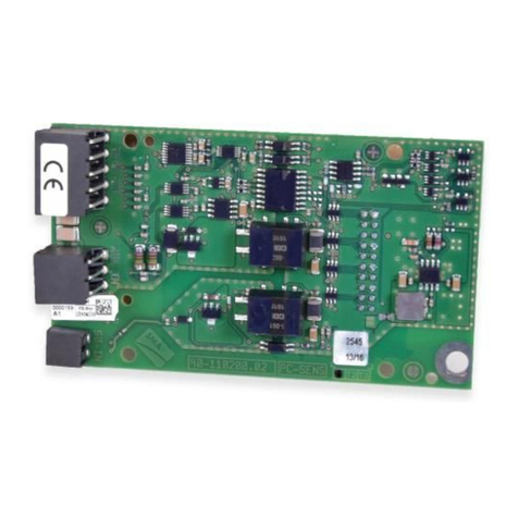
MD.IO-40 (PC-PWC.BG1)

Legal Provisions SMA Solar Technology AG
Installation manualMD-IO-40-IA-en-112
Legal Provisions
The information contained in these documents is the property of SMA Solar Technology AG. No part of this document
may be reproduced, stored in a retrieval system, or transmitted, in any form or by any means, be it electronic,
mechanical, photographic, magnetic or otherwise, without the prior written permission of SMA Solar Technology AG.
Internal reproduction used solely for the purpose of product evaluation or other proper use is allowed and does not
require prior approval.
SMA Solar Technology AG makes no representations or warranties, express or implied, with respect to this
documentation or any of the equipment and/or software it may describe, including (with no limitation) any implied
warranties of utility, merchantability, or fitness for any particular purpose. All such representations or warranties are
expressly disclaimed. Neither SMA Solar Technology AG nor its distributors or dealers shall be liable for any indirect,
incidental, or consequential damages under any circumstances.
The exclusion of implied warranties may not apply in all cases under some statutes, and thus the above exclusion may
not apply.
Specifications are subject to change without notice. Every attempt has been made to make this document complete,
accurate and up-to-date. Readers are cautioned, however, that product improvements and field usage experience may
cause SMA Solar Technology AG to make changes to these specifications without advance notice or per contract
provisions. SMA Solar Technology AG shall not be responsible for any damages, including indirect, incidental or
consequential damages, caused by reliance on the material presented, including, but not limited to, omissions,
typographical errors, arithmetical errors or listing errors in the content material.
SMA Warranty
You can download the current warranty conditions from the Internet at www.SMA-Solar.com.
Trademarks
All trademarks are recognized, even if not explicitly identified as such. Missing designations do not mean that a
product or brand is not a registered trademark.
SMA Solar Technology AG
Sonnenallee 1
34266 Niestetal
Germany
Tel. +49 561 9522-0
Fax +49 561 9522-100
www.SMA.de
Email: [email protected]
As of: 3/10/2021
Copyright © 2021 SMA Solar Technology AG. All rights reserved.

Table of Contents
SMA Solar Technology AG
Installation manual 3MD-IO-40-IA-en-11
Table of Contents
1 Information on this Document..................................................................................................... 4
1.1 Validity ............................................................................................................................................................. 4
1.2 Target Group ................................................................................................................................................... 4
1.3 Content and Structure of this Document......................................................................................................... 4
1.4 Levels of Warning Messages.......................................................................................................................... 4
1.5 Symbols in the Document................................................................................................................................ 4
1.6 Typographical Elements in the Document...................................................................................................... 5
1.7 Designations in the Document ........................................................................................................................ 5
2 Safety ............................................................................................................................................ 6
2.1 Intended Use.................................................................................................................................................... 6
2.2 IMPORTANT SAFETY INSTRUCTIONS......................................................................................................... 6
3 Scope of Delivery ......................................................................................................................... 8
4 Product Overview ........................................................................................................................ 9
4.1 SMA I/O modules........................................................................................................................................... 9
4.2 Type Label........................................................................................................................................................ 9
5 Mounting....................................................................................................................................... 11
5.1 Mounting position............................................................................................................................................ 11
5.2 Installing the Module....................................................................................................................................... 11
6 Connection .................................................................................................................................... 13
6.1 Cable Requirements ........................................................................................................................................ 13
6.2 Preparing the Connection Cable.................................................................................................................... 13
6.3 Inserting the Cables......................................................................................................................................... 13
6.4 Connecting the Ripple Control Receiver ........................................................................................................ 13
6.4.1 Connecting the Ripple Control Receiver......................................................................................................... 13
6.4.2 Use of the Ripple Control Receiver for further Inverters................................................................................. 15
6.5 Multifunction Relay Connection...................................................................................................................... 15
6.5.1 Connection to the Multifunction Relay............................................................................................................ 15
6.5.2 Changing the Operating Mode of the Multifunction Relay .......................................................................... 17
7 Decommissioning ......................................................................................................................... 18
7.1 Removing the Module..................................................................................................................................... 18
7.2 Packing the Product for Shipment................................................................................................................... 19
7.3 Disposing of the Product ................................................................................................................................. 19
8 Technical Data .............................................................................................................................. 20
9 EU Declaration of Conformity ..................................................................................................... 21
10 Contact .......................................................................................................................................... 22
1 Information on this Document SMA Solar Technology AG
Installation manualMD-IO-40-IA-en-114
1 Information on this Document
1.1 Validity
This document is valid for the SMA I/O Module (MD.IO-40) with assembly designation "PC-PWC.BG1" from
hardware version A1.
1.2 Target Group
The tasks described in this document must only be performed by qualified persons. Qualified persons must have the
following skills:
• Knowledge of how an inverter works and is operated
• Training in how to deal with the dangers and risks associated with installing, repairing and using electrical devices
and installations
• Training in the installation and commissioning of electrical devices and installations
• Knowledge of all applicable laws, standards and directives
• Knowledge of and compliance with this document and all safety information
1.3 Content and Structure of this Document
This document describes the installation, commissioning and decommissioning of the product.
You will find the latest version of this document and further information on the product in PDF format at www.SMA-
Solar.com.
Illustrations in this document are reduced to the essential information and may deviate from the real product.
1.4 Levels of Warning Messages
The following levels of warning messages may occur when handling the product.
DANGER
Indicates a hazardous situation which, if not avoided, will result in death or serious injury.
WARNING
Indicates a hazardous situation which, if not avoided, could result in death or serious injury.
CAUTION
Indicates a hazardous situation which, if not avoided, could result in minor or moderate injury.
NOTICE
Indicates a situation which, if not avoided, can result in property damage.
1.5 Symbols in the Document
Symbol Explanation
Information that is important for a specific topic or goal, but is not safety-relevant
☐
Indicates a requirement for meeting a specific goal
☑
Desired result

1 Information on this Document
SMA Solar Technology AG
Installation manual 5MD-IO-40-IA-en-11
Symbol Explanation
✖
A problem that might occur
Example
1.6 Typographical Elements in the Document
Typography Use Example
bold • Messages
• Terminals
• Elements on a user interface
• Elements to be selected
• Elements to be entered
• Connect the insulated conductors
to the terminals X703:1 to
X703:6.
• Enter 10 in the field Minutes.
>• Connects several elements to be
selected
• Select Settings > Date.
[Button]
[Key]
• Button or key to be selected or pressed • Select [Enter].
# • Placeholder for variable components
(e.g., parameter names)
• Parameter WCtlHz.Hz#
1.7 Designations in the Document
Complete designation Designation in this document
PV system PV system
SMA I/O modules Module, product

2 Safety SMA Solar Technology AG
Installation manualMD-IO-40-IA-en-116
2 Safety
2.1 Intended Use
The SMA I/O Module is a module with 6 digital inputs and 1 digital output operating as a multifunction relay. The
SMA I/O Module enables the implementation of grid management services for up to 12 SMA inverters in a network
with the same system password. The SMA I/O Module must be installed in one SMA inverter. For the implementation
of grid management services, the SMA I/O Module receives the specifications of the grid operator via a ripple control
receiver. The SMA I/O Module transmits the specifications of the grid operator via Speedwire network to a maximum
of 11 further SMA inverters. The multifunction relay can be configured for various operating modes. The multifunction
relay can, for example, be used for switching fault indicators on and off.
The product must only be installed in the following SMA inverters:
• STP 50-40 (SunnyTripowerCORE1)
• STP 50-41 (SunnyTripowerCORE1)
• STP 50-JP-40 (Sunny Tripower CORE1-JP)
The inverter still complies with the standard after the product has been installed.
All components must remain within their permitted operating ranges and their installation requirements at all times.
The product must only be used in countries for which it is approved or released by SMA Solar Technology AG and the
grid operator.
Use SMA products only in accordance with the information provided in the enclosed documentation and with the
locally applicable laws, regulations, standards and directives. Any other application may cause personal injury or
property damage.
Alterations to the SMA products, e.g., changes or modifications, are only permitted with the express written permission
of SMA Solar Technology AG. Unauthorized alterations will void guarantee and warranty claims and in most cases
terminate the operating license. SMA Solar Technology AG shall not be held liable for any damage caused by such
changes.
Any use of the product other than that described in the Intended Use section does not qualify as the intended use.
The enclosed documentation is an integral part of this product. Keep the documentation in a convenient, dry place for
future reference and observe all instructions contained therein.
This document does not replace and is not intended to replace any local, state, provincial, federal or national laws,
regulations or codes applicable to the installation, electrical safety and use of the product. SMA Solar Technology AG
assumes no responsibility for the compliance or non-compliance with such laws or codes in connection with the
installation of the product.
The type label must remain permanently attached to the product.
2.2 IMPORTANT SAFETY INSTRUCTIONS
Keep the manual for future reference.
This section contains safety information that must be observed at all times when working.
The product has been designed and tested in accordance with international safety requirements. As with all electrical
or electronical devices, there are residual risks despite careful construction. To prevent personal injury and property
damage and to ensure long-term operation of the product, read this section carefully and observe all safety
information at all times.

2 Safety
SMA Solar Technology AG
Installation manual 7MD-IO-40-IA-en-11
DANGER
Danger to life due to electric shock when live components or cables of the inverter are touched
High voltages are present in the conductive components or cables of the inverter. Touching live parts and cables of
the inverter results in death or lethal injuries due to electric shock.
• Disconnect the inverter from voltage sources and make sure it cannot be reconnected before working on the
device.
• Wear suitable personal protective equipment for all work on the product.
NOTICE
Damage to the enclosure seal in subfreezing conditions
If you open the inverter when temperatures are below freezing, the enclosure seals can be damaged. This can lead
to moisture entering the inverter.
• Only open the inverter if the ambient temperature is not below -5°C.
• If a layer of ice has formed on the enclosure seal when temperatures are below freezing, remove it prior to
opening the inverter (e.g. by melting the ice with warm air).
NOTICE
Damage to the product due to sand, dust and moisture ingress
Sand, dust and moisture penetration can damage the product and impair its functionality.
NOTICE
Damage to the inverter or product due to electrostatic discharge
Touching electronic components can cause damage to or destroy the inverter or the product through electrostatic
discharge.
• Ground yourself before touching any component.
NOTICE
Manipulation of system data in networks
You can connect the supported SMA products to the Internet. When connected to the Internet, there is a risk that
unauthorized users can access and manipulate the data of your system.
DHCP Server is recommended.
The DCHP server automatically assigns the appropriate network settings to your nodes in the local network. A
manual network configuration is therefore not necessary. In a local network, the Internet router is usually the
DHCP server. If the IP addresses in the local network are to be assigned dynamically, DHCP must be activated in
the Internet router (see the Internet router manual). In order to receive the same IP address by the internet router
after a restart, set the MAC address binding.
In networks where no DHCP server is active, proper IP addresses must be assigned from the free address pool of
the network segment to all network participants to be integrated during commissioning.

3 Scope of Delivery SMA Solar Technology AG
Installation manualMD-IO-40-IA-en-118
3 Scope of Delivery
Check the scope of delivery for completeness and any externally visible damage. Contact your distributor if the scope
of delivery is incomplete or damaged.
EB DC
A
Figure 1: Components included in the scope of delivery
Position Quantity Designation
A 1 Module of device type "PC-PWC.BG1"
B 1 Fastening screw (M5, TX25)
C 2 4-pole plug
D 1 Three-pole plug
E 1 Quick reference guide for commissioning

4 Product Overview
SMA Solar Technology AG
Installation manual 9MD-IO-40-IA-en-11
4 Product Overview
4.1 SMA I/O modules
The SMA I/O Module is a module with 6 digital inputs and 1 digital output operating as a multifunction relay. The
SMA I/O Module enables the implementation of grid management services for up to 12 SMA inverters in a network
with the same system password. The SMA I/O Module must be installed in one SMA inverter. For the implementation
of grid management services, the SMA I/O Module receives the specifications of the grid operator via a ripple control
receiver. The SMA I/O Module transmits the specifications of the grid operator via Speedwire network to a maximum
of 11 further SMA inverters. The multifunction relay can be configured for various operating modes. The multifunction
relay can, for example, be used for switching fault indicators on and off.
Design of the module
E
A
C
D
B
Figure 2: Design of the module
Position Designation Explanation
A – Opening for the fastening screw
B – Openings for the guide pins of the communication assembly
COUTPUT Multifunction Relay Connection
DINPUT Terminals for ripple control receiver
E – Connector strip on the back of the module for connection to the com-
munication assembly in the inverter
4.2 Type Label
The type label clearly identifies the product. The type label is located on the front of the product.
PC-PWC.BG1
XXXXX
XX
A
B
C
Figure 3: Design of the type label
Position Explanation
A Device type

5 Mounting
SMA Solar Technology AG
Installation manual 11MD-IO-40-IA-en-11
5 Mounting
5.1 Mounting position
DISPLAY
BAT
Max. 30V DC
USB
FCC ID: SVF-KP
IC: 9440A-KP20
MFR
AB
X1 X2
A
B
C
Figure 4: Communication assembly in the inverter with mounting position for the module
Position Designation
A Communication assembly
BModule slot M1*
CModule slot M2
* Production resources SMA Solar Technology AG recommends using module slot M1 for the module.
5.2 Installing the Module
DANGER
Danger to life due to high voltages of the PV array
When exposed to sunlight, the PV array generates dangerous DC voltage, which is present in the DC conductors
and the live components of the inverter. Touching the DC conductors or the live components can lead to lethal
electric shocks.
• Prior to performing any work on the inverter, always disconnect the inverter from voltage sources on the AC
and DC sides as described in the inverter manual. When doing so, note that even if the DC load-break is
switched off, there will be dangerous direct voltage present in the DC conductors of the inverter.
NOTICE
Damage to the product due to sand, dust and moisture ingress
Sand, dust and moisture penetration can damage the product and impair its functionality.
Maximum number of modules per inverter
You can only use a maximum of one module of the same device type per inverter.
Procedure:
1. Disconnect the inverter from voltage sources (at www.SMA-Solar.com).
2. Remove the enclosure lid of the DC Connection Unit. Unscrew all screws with a Torx screwdriver (TX25) and
remove the enclosure lid carefully forward.

5 Mounting SMA Solar Technology AG
Installation manualMD-IO-40-IA-en-1112
3. Set the screws and the enclosure lid aside and store safely.
4. Install the module at the desired mounting location. Perform the following steps:
• Guide the 3 guide pins on the communication assembly
through the holes in the module. The holes in which the guide
pins must be inserted depend on the mounting location.
• Carefully push the module down on the upper edge and on
the connection sockets until it audibly snaps into both side
locking tabs of the communication assembly. The connector
strip on the back of the module is automatically pushed into
the socket terminal strip of the communication assembly.
CLICKCLICK
5. Screw tight the fastening screw with a Torx screwdriver (TX25) on
the module (torque: 1.5Nm). This additionally fixes the module in
place and grounds it in the inverter enclosure.

6 Connection
SMA Solar Technology AG
Installation manual 13MD-IO-40-IA-en-11
6 Connection
6.1 Cable Requirements
UV resistance of connection cables
Connection cables to be laid outdoors must be UV-resistant or routed in a UV-resistant cable channel.
☐ Number of conductors:
For connecting the ripple control receiver: at least five insulated conductors
For connecting to the multifunction relay: at least two insulated conductors
Tip: You can use one common cable with at least seven insulated conductors to connect both the ripple control
receiver and the multifunction relay
☐ Conductor cross-section: 0.5mm²to0.75mm²
☐ Maximum cable length: 100m
6.2 Preparing the Connection Cable
Always proceed as follows to prepare each connection cable for connection to multipole terminal blocks.
Procedure:
1. Strip 40mm of cable sheath from the end of the connection cable to which the multipole terminal block is to be
attached. Make sure that no pieces of cable are dropped into the inverter.
2. Strip off 6mm of the conductor insulation from each of the required connection cable conductors (see Section6.1
"Cable Requirements", page13).
3. Trim unneeded insulated conductors of the connection cable flush with the cable sheath.
4. Push one bootlace ferrule onto each stripped insulated conductor up to the stop, if necessary.
6.3 Inserting the Cables
Additionally required material (not included in the scope of delivery):
☐ Connection cable (see Section6.1 "Cable Requirements", page13)
Procedure:
1. Make sure that the inverter has been disconnected and is secured against reconnection (see the inverter manual).
2. Remove the swivel nut from the cable gland for the communication cable.
3. Thread the swivel nut over the cable.
4. Press the two-hole cable support sleeve out of the cable gland.
5. Remove the sealing plug from one of the enclosure openings of the two-hole cable support sleeve and insert the
cable into the enclosure opening.
6. Press the two-hole cable support sleeve with the cable into the cable gland and guide the cable to the
communication assembly in the DC Connection Unit. Ensure that any unused enclosure openings of the two-hole
cable support sleeve are sealed with sealing plugs.
7. Tighten the swivel nut on the cable gland hand-tight. This will secure the cable.
6.4 Connecting the Ripple Control Receiver
6.4.1 Connecting the Ripple Control Receiver
The digital signals for the specifications to the grid management services are transmitted to the INPUT terminal of the
module. Up to 6 control signals can be transmitted.

6 Connection SMA Solar Technology AG
Installation manualMD-IO-40-IA-en-1114
Additionally required material (not included in the scope of delivery):
☐ 1 ripple control receiver
Requirements:
☐ The ripple control receiver must be technically suitable for connection to the digital inputs (see Section8
"Technical Data", page20).
☐ The connection cable is prepared for connection to the multipole plug (see Section6.2 "Preparing the Connection
Cable", page13).
☐ The connection cable must be inserted through the cable gland into the inverter (see Section6.3 "Inserting the
Cables", page13).
Pin assignment:
A
B
B1B1 B2B2 B3B3 B4B4
A1A1 A2A2 A3A3 A4A4
Figure 5: Pin assignment for terminal INPUT
Pin row Pin Assignment Explanation
B B1 24V Voltage supply output
B2 IN Digital input1
B3 IN Digital input2
B4 IN Digital input3
A A1 24V Voltage supply output
A2 IN Digital input4
A3 IN Digital input5
A4 IN Digital input6
Circuitry overview:
B1
B2
B3
B4
A1
A2
A3
A4
K1
K2
K3
K4
SMA I/O Module Ripple control receiver
Figure 6: Connection of a ripple control receiver

6 Connection
SMA Solar Technology AG
Installation manual 15MD-IO-40-IA-en-11
DANGER
Danger to life due to electric shock from faulty connection of the ripple control receiver
Incorrect connection of the ripple control receiver can result in grid voltage on the inverter enclosure. Touching the
live enclosure results in death or lethal injuries due to electric shock.
• Do not connect the insulated conductors of the connection cable to the line conductors of the ripple control
receiver.
• When connecting, ensure that no bridge is being used in the ripple control receiver.
Procedure:
1. Connect the connection cable to the ripple control receiver (see the manual from manufacturer). Trim the unused
insulated conductors up to the cable sheath and write down the conductor colors of the required insulated
conductors.
2. Connect the connection cable to the four-pole plug as follows:
• Depending on the ripple control receiver and the pin assignment in terminal INPUT, identify the conductor
entries that are required for connecting the connection cable. The voltage supply (24V) only needs to be
connected once.
• Release the required conductor entries using a screwdriver and insert the insulated conductors into the
conductor entries. Ensure that the noted conductor colors correspond to the pin assignment of the connection
INPUT.
3. Insert the four-pole plug at terminal INPUT into the desired pin row.
4. If needed, make more connections on the module (see Section6.4.2 "Use of the Ripple Control Receiver for
further Inverters", page15).
5. If no further connections are required on the module, close the inverter and commission it (see the inverter
manual).
6. Configure the digital inputs via the installation assistant of the inverter user interface (see the inverter manual for
login information and for how to start the installation assistant).
6.4.2 Use of the Ripple Control Receiver for further Inverters
You can use the signal from one ripple control receiver for a maximum of twelve inverters. To this end, you must only
equip one of the inverters in the PV system with the module. This inverter forwards the signals of the ripple control
receiver via communication signal via LAN or WLAN to the other inverters in the PV system. For this, all inverters must
be located in the same local network and have the same PV system password.
6.5 Multifunction Relay Connection
6.5.1 Connection to the Multifunction Relay
Operating modes and connection option
The operating modes and connection options of the multifunctional relay on the module are identical to the
operating modes and connection options of the multifunctional relay on the communication assembly of the
inverter. For more information see the inverter manual at www.SMA-Solar.com.
Requirements:
☐ You must select the connection option depending on the desired function of the multifunction relay (see inverter
manual).
☐ The contactors must be technically suitable for connection to the multifunction relay (see Section8 "Technical
Data", page20).
☐ The remote terminal must be technically suitable for connection to the multifunction relay (see Section8 "Technical
Data", page20).

6 Connection SMA Solar Technology AG
Installation manualMD-IO-40-IA-en-1116
☐ The connection cable must be prepared for connection to the multipole plug (see Section6.2 "Preparing the
Connection Cable", page13).
☐ The connection cable must be inserted through the cable gland into the inverter (see Section6.3 "Inserting the
Cables", page13).
112233
Figure 7: Pin assignment for terminal OUTPUT
Pin Explanation
1 Make contact
2 Change-over contact
3 Break contact
Procedure:
WARNING
Danger to life due to electric shock if the maximum switching voltage of the multifunction relay
is exceeded
The multifunction relay is designed for a maximum switching voltage of 30VDC. Connecting a remote terminal with
higher voltage can result in death or serious injury from electric shock.
• Observe the maximum switching voltage of 30VDC when making the connection.
NOTICE
Minimum switching current required to prevent surface corrosion of the relay contacts
Surface corrosion can impair the functionality of the multifunction relay. In order to prevent surface corrosion of the
relay contacts, a minimum current must flow over the relay at the moment of switching.
• If the relay does not switch a load but only a control signal, make sure that a minimum switching current of
10mA flows over the relay at the 10V switching moment.
1. Connect the connection cable to the remote terminal (see the remote terminal manual). Trim the unused insulated
conductors up to the cable sheath and write down the conductor colors.
2. Connect the connection cable to the three-pole plug:
• Depending on the remote terminal and the pin assignment on the terminal OUTPUT identify the conductor
entries that are required for connecting the connection cable.
• Release the required conductor entries using a screwdriver and insert the insulated conductors into the
conductor entries. Make sure that the noted conductor colors correspond to the pin assignment on the
terminal OUTPUT.
3. Insert the three-pole plug into the pin row in terminal OUTPUT.
4. If no further connections are required on the module, close the inverter and commission it (see the inverter
manual).
5. Change the operating mode of the multifunction relay, if required (see Section6.5.2 "Changing the Operating
Mode of the Multifunction Relay", page17).

6 Connection
SMA Solar Technology AG
Installation manual 17MD-IO-40-IA-en-11
6.5.2 Changing the Operating Mode of the Multifunction Relay
Changing the operating mode with two existing multifunction relays
For inverters with an internal multifunction relay on the communication module and an additional multifunction
relay on an SMA I/O module, the operating mode can be changed separately for each multifunction relay. The
parameters of the internal multifunction relay are marked with [A] on the inverter user interface. The parameters of
the multifunction relay on the SMA I/O module are marked with [B].
The default operating mode of the multifunction relay is Fault indication (FltInd) . If you decide to use another
operating mode and have established the correct electrical connection for this operating mode and the associated
connection variant, you will have to change the operating mode of the multifunction relay and make other settings, if
necessary.
Procedure:
1. Activate the user interface of the inverter (see the inverter manual).
2. Log in as Installer or User.
3. Call up the menu Device Parameters.
4. Select [Edit parameters].
5. In the parameter group Device > Multifunction relay > Operating mode select the parameter Operating
mode of multifunction relay or Mlt.OpMode and set the desired operating mode.
6. Once you have set the operating mode Self-consumption or SelfCsmp, you can configure other settings:
• In the parameter group Device > Multifunction relay > Self-consumption > Minimum On power select
the parameter Minimum On power for MFR self-consumption or Mlt.MinOnPwr and set the desired
value. This will configure the power threshold from which a load is to be activated.
• In the parameter group Device > Multifunction relay > Self-consumption > Minimum power On time
select the parameter Minimum power On time, MFR self-consumption or Mlt.MinOnPwrTmm and set
the desired value. This will configure the minimum time for which the power must have exceeded the minimum
switch-on power threshold in order to trip activation of the load.
• In the parameter group Device > Multifunction relay > Self-consumption > Minimum On power select
the parameter Minimum On time for MFR self-consumption or Mlt.MinOnTmm and set the desired
value. This will configure the minimum time for which the load remains activated.
7. If you have set the operating mode Control via communication or ComCtl, in the parameter group Device >
Multifunction relay > Control via communication > Status select the parameter Status of MFR with
control via communication or Mlt.ComCtl.Sw and set the desired value. This determines whether the
multifunction relay can be controlled via a communication product.
8. If you have set the operating mode Battery bank or BatCha, make further settings:
• In the parameter group Device > Multifunction relay > Battery bank > Minimum On power select the
parameter Minimum On power for MFR battery bank or Mlt.BatCha.Pwr and set the desired value.
This will configure the power threshold from which the battery is to be charged.
• In the parameter group Device > Multifunction relay > Battery bank > Minimum time before
reconnection select the parameter Minimum time before reconnection of MFR battery bank or
Mlt.BatCha.Tmm and set the desired value. This will configure the minimum time which must elapse after
charging the battery before the battery can be charged again.
9. Select [Save all] to save the changes.

7 Decommissioning SMA Solar Technology AG
Installation manualMD-IO-40-IA-en-1118
7 Decommissioning
7.1 Removing the Module
DANGER
Danger to life due to high voltages of the PV array
When exposed to sunlight, the PV array generates dangerous DC voltage, which is present in the DC conductors
and the live components of the inverter. Touching the DC conductors or the live components can lead to lethal
electric shocks.
• Prior to performing any work on the inverter, always disconnect the inverter from voltage sources on the AC
and DC sides as described in the inverter manual. When doing so, note that even if the DC load-break is
switched off, there will be dangerous direct voltage present in the DC conductors of the inverter.
NOTICE
Damage to the product due to sand, dust and moisture ingress
Sand, dust and moisture penetration can damage the product and impair its functionality.
Procedure:
1. Disconnect the inverter from voltage sources (at www.SMA-Solar.com).
2. Remove the enclosure lid of the DC Connection Unit. Unscrew all screws with a Torx screwdriver (TX25) and
remove the enclosure lid carefully forward.
3. Set the screws and the enclosure lid aside and store safely.
4. Remove all connecting terminal plates from the used connection sockets of the module.
5. Unscrew the fastening screw on the module using a Torx
screwdriver (TX25).
6. Remove the module:
• Press the right or left locking tab of the communication
assembly slightly outwards and pull the module slightly
forwards holding the lower end until the module is released
from the interlock of the locking tab.
1
2
• Grab the module by the upper and lower edge with one hand.

7 Decommissioning
SMA Solar Technology AG
Installation manual 19MD-IO-40-IA-en-11
• Slightly press the second locking tab outwards using the
other hand and pull the module slightly forwards on the
lower end until the module is released from the interlock of
the locking tab.
1
2
• Remove the module from its slot by pulling it forwards.
7. Remove the swivel nut from the cable gland for the communication cable.
8. Lead the connection cable out of the two-hole cable support sleeve.
9. Lead the connection cable out of the swivel nut.
10. Close unused enclosure openings of the two-hole cable support sleeve with sealing plugs.
11. Press the cable support sleeve into the two-hole cable gland.
12. Tighten the swivel nut on the cable gland hand-tight.
13. Close the inverter and, if necessary, recommission it (see inverter manual).
7.2 Packing the Product for Shipment
• Pack the product for shipping. Use the original packaging or packaging that is suitable for the weight and size of
the product.
7.3 Disposing of the Product
• Dispose of the product in accordance with the locally applicable disposal regulations for electronic waste.

8 Technical Data SMA Solar Technology AG
Installation manualMD-IO-40-IA-en-1120
8 Technical Data
General Data
Mounting location In the inverter
Voltage supply Via the inverter
Mechanical Data
Width x height x depth 60mm x 105 mm x 33mm
Ambient Conditions for Storage/Transport
Ambient temperature -40°C to +70°C
Relative humidity, non-condensing 10% to 100%
Maximum height above mean sea level 3000m
Digital inputs
Quantity 6
Input voltage 24VDC
Cutoff frequency 30Hz
Maximum cable length 100m
Digital outputs (multifunction relay)
Quantity 3
Execution Potential-free relay contacts
Maximum switching voltage 30VDC
Maximum switching current 1A
Minimum switching current 10mA
Minimum electrical endurance when the maximum switch-
ing voltage and maximum switching current are complied
with
100000 switching cycles
Bounce time 5 ms
Reset time 5 ms
Maximum cable length 100m
Table of contents
Other SMA Control Unit manuals

SMA
SMA SWDMSI-10.BG1 User manual

SMA
SMA JBOX TS4-R-O 600VUL User manual

SMA
SMA 485 User manual

SMA
SMA MD.SEN-40 User manual

SMA
SMA MD.485-US-40 User manual

SMA
SMA MD.485-40 User manual

SMA
SMA MD.SEN-US-40 User manual

SMA
SMA 1C4-313-001-001 Operating and safety instructions

SMA
SMA 485 Data Module User manual

SMA
SMA MD.485-US-40 User manual
Popular Control Unit manuals by other brands

Frequency Central
Frequency Central Continuum Phaser ii Build documentation

Beckhoff
Beckhoff AX5021 Documentation

AVCO
AVCO 9100 Series Installation, operation & maintenance manual

Texas Instruments
Texas Instruments TPS546C23 user guide

ABB
ABB RER 133 Technical description

Woodward
Woodward easYgen-1000 Installation