manuals.online logo
Brands
  1. Home
  2. •
  3. Brands
  4. •
  5. teko
  6. •
  7. Control Unit
  8. •
  9. teko Astra-PSTN User manual

teko Astra-PSTN User manual

Astra-PSTN Module
Operating Manual
Rev. PSTN-v1_3_en
The operating manual describes the operating principle, op-
erational and maintenance conditions pertaining to module As-
tra-PSTN (hereinafter referred to as “module”) (Fig.1).
The manufacturer reserves the right to introduce changes
which update and retrofit the device without prior notice. All
such changes will be described in an updated revision of the
operating manual.
1 Function
1.1 The module operates as a part of “Astra”-type devices
which can house it (Astra-812Мor Astra-Z-812Мcontrol pa-
nels, hereinafter referred to as “control panel”).
1.2 The module operates in the two-wire public switched tel-
ephone network and sends voice, tone or digital messages (in
Contact ID, SIA FSK format).
Note –In Astra-Zitadel system, the module sends digital mes-
sages only.
1.3 The module is intended for continuous 24h use.
2 Specifications
Power supply voltage, V ............................................ 3.3 ± 0.1
Current consumption, mA, max ..........................................100
Communication line...................... standard two-wire telephone
Overall dimensions, mm, max .............................. 65 28 11
Weight, kg, max..................................................................0.02
Operating Conditions
Temperature range, оС................................ from -10 up to +55
Relative air humidity,................................. up to 93 at + 40 C
no moisture condensation
3 Delivery Set
Astra-PSTN module..........................................................1 pcs.
Operating manual...........................................................1 copy.
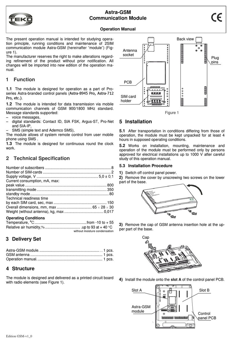
4 Structure
Structurally, the module is comprised of the printed circuit
board with radio elements (Fig. 1).
Fig. 1
5 Module Installation
5.1 If shipping conditions differ from operating conditions,
unpack the detector and wait for at least 4 hours before instal-
ling it.
5.2 Only personnel familiarized with the operating manual
and cleared to operate electric equipment of up to 1000V are
allowed to mount, service and operate the module.
5.3 Installation Procedure
1) Switch off the control panel power supply.
2) Open the control panel cover by unscrewing two screws
from the front side of the base.
3) Remove the keyboard printed circuit board by unscrew-
ing four mounting screws.
4) Remove the keyboard fixing plank by unscrewing two
mounting screws.
5) Install the module; the module shall be positioned in ac-
cordance with marks (triangles), printed on PCBs of the mod-
ule and the control panel.
6) Pull the telephone wire though the telephone wire hole,
providing for hidden wire layout. Wiring to the control panel
terminals shall be carried out is accordance with item 7.
Plugs
Printed cir-
cuit board
Marking for correct
positioning during the
installation into the
control panel
Back view
Base
PCB
PSTN module
Telephone wire hole
____________________
*Available at www.controlex.eu Rev. PSTN-v1_3_en
7) Place the keyboard fixing plank and the keyboard PCB
back into their positions.
WARNING! If the keyboard bus line got disconnected from the
socket, reconnect it in strict accordance with markings, printed
on the bus line and the socket.
8) Close the control panel cover by screwing two screws into
the front side of the base.
6 Module Setting
6.1 Module Registration
Module registration is required in the Astra-Zitadel system on-
ly. It is not required to register the module in the Observer I
system.
The module is registered after the installation in accordance
with guidelines given in the operating manual for the Astra-
Zitadel system*.
6.2 Module Setting
The module is set from the PC using a corresponding setting
program Pconf* in accordance with guidelines given in the op-
erating manual for the selected system.
WARNING!
1) When entering a recipient’s number, do not forget to enter
a special symbol –“W”- waiting for the ringing tone in the line
–after “9”for local calls or “8”for international calls (e.g.,
9W8W432789598).
2) If the recipient’s number has an extension number, enter a
special symbol –“B”- waiting for silence in the line after the
main number is dialed (e.g., 2789598B183).
3) The module might not work with some mini ATX or national
(international) numbers.
7 Connecting the Module to the Telephone
Line
7.1 The control panel PCB is equipped with screw terminals;
they are used to connect the telephone line and fixed tele-
phone equipment. It is not necessary to observe proper polari-
ty when connecting to the terminals!
Terminal functions are given in Table 1.
Table 1
Terminal
Function
Terminals are used when the module is in-
stalled in the Socket Аslot of the control
panel.
In the Astra-Zitadel system:
SA1- to connect the telephone line;
SA2- to connect a telephone set (fax).
In the Observer I system:
SA1- to connect a telephone set (fax);
SA2- to connect the telephone line
Terminals are used when the module is in-
stalled in the Socket B slot of the control
panel and only in the Astra-Zitadel system.
SB1 - to connect the telephone line
7.2 Enter the engineer menu of the control panel using the
engineer’s password and include the module in data ex-
change with the control panel.
8 Remote Control Using the Module
Objects can be remotely controlled using the PSTN module in
the Observer I system only. Remote control is carried out in
accordance with guidelines given in the operating manual for
the Observer I system*.
9 Labeling
The label glued to the module PCB contains the bar code with
the following information:
- module name or abbreviated designation;
- firmware version;
- month and year of manufacture (last two digits).
10 EC Conformity Declarations
This product is in conformity with the provisions of:
LVD 73/23/EEC+93/68/EEC
EMC 89/336/EEC
EN 61000-6-3:2005 Electromagnetic compatibility (EMC) -
Part 6-3: Generic standards - Emission standard for
residential, commercial and light-industrial environments.
EN 50130-4:1995 + A1:1998 + A2:2003 + Corrig. 2003 Alarm
systems - Part 4: Electromagnetic compatibility - Product
family standard: Immunity requirements for components of fire,
intruder and social alarm systems.
EN 60950-1: 2001+A11:2004+Corrig.2004 Safety of informa-
tion technology equipment.
11 Recycling
The module does not pose any life or health risk to individuals
or to the environment. Once its service life is complete, the
module may be utilized with no special environment protection
measures.
12 Manufacturer Warranties
12.1 The manufacturer warrants that the module will meet re-
quirements of technical specifications if a user follows all ship-
ping, storage, mounting and operating guidelines.
12.2 Guaranteed storage life –5 years and 6 months from the
manufacture date.
12.3 Guaranteed service life –5 years from the commission-
ing, but not more than 5 years and 6 months from the manu-
facture date.
12.4 The manufacturer shall repair or replace a faulty module
during the warranty period.
12.5 The warranty becomes void if:
–the userdoes not followguidelines of the operating manual;
–the module is mechanically damaged;
–the module is repaired by a party other than the Manufacturer.
12.6 The warranty covers the module only. All equipment
manufactured by other parties and used with the module is
covered by its respective warranty.
The manufacturer shall not be responsible for personnel
death, injury, and damage to equipment or other acciden-
tal or deliberate losses based on user’s claims that the
module failed to function properly.
Sales:
Controlex GmbH
Warranty service and
technical support:
ТЕКО-TD
Philosophenweg 31-33
47051 Duisburg, Germany
Phone: +49 (0) 203 / 393 91 188
Fax: +49 (0) 203 / 393 91 189
GSM: +49 (0) 178 / 218 48 22
E-mail: info@controlex.eu
Web: www.controlex.eu
Prospect Pobedy str. 19
420138 Kazan, Russia
Phone: +7 (843) 261-55-75
Fax: +7 (843) 261-58-08
E-mail: info@teko.biz
support@teko.biz
Web: www.teko.biz
Made in Russia

Other teko Control Unit manuals

teko ASTRA-LAN User manual

teko

teko ASTRA-LAN User manual

teko ASTRA-GSM User manual

teko

teko ASTRA-GSM User manual

teko Astra-GSM User manual

teko

teko Astra-GSM User manual

Popular Control Unit manuals by other brands

Siemens SIRIUS 3RF2330-DA Series Original operating instructions

Siemens

Siemens SIRIUS 3RF2330-DA Series Original operating instructions

ABB 07 MK 92 R1161 operating manual

ABB

ABB 07 MK 92 R1161 operating manual

Huawei EM770S manual

Huawei

Huawei EM770S manual

Acetech AT2000R user manual

Acetech

Acetech AT2000R user manual

Econ ERIKS Installation & operation manual

Econ

Econ ERIKS Installation & operation manual

Siedle BTLM 650-04 Product information

Siedle

Siedle BTLM 650-04 Product information

KYL KYL-300M quick start guide

KYL

KYL KYL-300M quick start guide

CKD QEV2 instruction manual

CKD

CKD QEV2 instruction manual

Tyco Star Hydrus S30 manual

Tyco

Tyco Star Hydrus S30 manual

Allen-Bradley 1794-VHSC user manual

Allen-Bradley

Allen-Bradley 1794-VHSC user manual

Valcom V-2003A brochure

Valcom

Valcom V-2003A brochure

Balluff BNI EIP-508-005-E002 user guide

Balluff

Balluff BNI EIP-508-005-E002 user guide

SEA USER 1 - 24v DG R1 manual

SEA

SEA USER 1 - 24v DG R1 manual

Warmup S Series installation manual

Warmup

Warmup S Series installation manual

Strahman Bi-Torq BT Series Operation and maintenance manual

Strahman

Strahman Bi-Torq BT Series Operation and maintenance manual

Weidmüller FH-TH Series operating instructions

Weidmüller

Weidmüller FH-TH Series operating instructions

VeEX UX400 user manual

VeEX

VeEX UX400 user manual

RoboMaster PM01 user guide

RoboMaster

RoboMaster PM01 user guide

manuals.online logo
manuals.online logoBrands
  • About & Mission
  • Contact us
  • Privacy Policy
  • Terms and Conditions

Copyright 2025 Manuals.Online. All Rights Reserved.