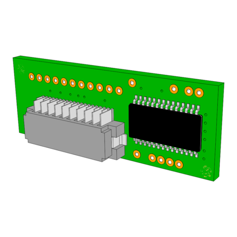
NCR K150 Operating instructions

NCR — CONFIDENTIAL AND PROPRIETARY
Use pursuant to Company Instructions
NCR K150/F150 IMAGING
MODULE
Programming Guide
B005-0000-2166
November 2012
Front Cover

EMC COMPLIANCE
Federal Communications Commission (FCC) Radio Frequency Interference Statement
This equipment has been tested and found to comply with the limits for a Class A digital device, pursuant to Part 15 of the FCC Rules.
These limits are designed to provide reasonable protection against harmful interference when the equipment is operated in a commercial
environment. This equipment generates, uses, and can radiate radio frequency energy and, if not installed and used in accordance with
the instruction manual, may cause harmful interference to radio communications. Operation of this equipment in a residential area is
likely to cause harmful interference in which case the user will be required to correct the interference at his own expense.
Canadian Class A Device Declaration
This digital apparatus does not exceed the Class A limits for radio noise emissions from digital apparatus set out in the Radio Interference
Regulations of the Canadian Department of Communications.
Le présent appareil numérique n’émet pas de bruits radioélectriques dépassant les limites applicables aux appareils numériques de la
classe A prescrites dans le Réglement sur le brouillage radioélectrique édicté par le ministère des Communications du Canada.
EU EMC Directive 2004/108/EC
This equipment has been found to comply with the essential requirements of EMC Directive 2004/108/EC, by testing to harmonized
standard, EN55022 and EN55024. The equipment complies with the limits for a Class A digital device, pursuant to EN55022.
This is a Class A product, in a domestic/residential environment this product may cause radio interference in which case the user may
be required to take adequate measures.
Information to User
This equipment must be installed and used in strict accordance with the manufacturer’s instructions. However, there is no guarantee that
interference to radio communications will not occur in a particular commercial installation. If this equipment does cause interference,
which can be determined by turning the equipment off and on,the user is encouraged to consult an NCR service representative immediately.
CAUTION
NCR Corporation is not responsible for any radio or television interference caused by unauthorised
modifications of this equipment or the substitution or attachment of connecting cables and equipment
other than those specified by NCR. Such unauthorized modifications, substitutions, or attachments may
void the user’s authority to operate the equipment. The correction of interference caused by such
unauthorized modifications, substitutions, or attachments will be the responsibility of the user.
The product described in this book is a licensed product of NCR Corporation.
NCR Proprietary Information - not to be disclosed or reproduced without written consent.
NCR and NCR SelfServ are trademarks of NCR Corporation.
Other product names mentioned in this publication may be trademarks or registered trademarks of their respective companies and are
hereby acknowledged.
It is the policy of NCR Corporation (NCR) to improve products as new technology, components, software, and firmware become available.
NCR, therefore, reserves the right to change specifications without prior notice.
All features, functions, and operations described herein may not be marketed by NCR in all parts of the world. In some instances,
photographs are of equipment prototypes. Therefore, before using this document, consult with your NCR representative or NCR office
for information that is applicable and current.
© 2011–2012
By NCR Corporation, Duluth, Georgia, U.S.A.
http://www.ncr.com
All Rights Reserved

REVISION RECORD
Date Revision Page Description of Change
May 2011 A All Initial Release. Conversion from third party document to IP
standards.

To help maintain the quality of NCR publications, please send feedback on their accuracy,
clarity or usability to:
For technical or sales queries, please contact your local NCR support.

NCR K150/F150 IMAGING MODULE
Table of Contents
November 2012 3
NCR — CONFIDENTIAL AND PROPRIETARY
Use pursuant to Company Instructions
Table of Contents
NCR K150/F150 IMAGING MODULE
Chapter 1: Getting Started
INTRODUCTION ........................................................................................................... 1-1
UNPACKING THE DEVICE ......................................................................................... 1-2
READING TECHNIQUES ............................................................................................. 1-2
SETTING CUSTOM DEFAULTS ................................................................................. 1-3
RESETTING THE CUSTOM DEFAULTS.................................................................... 1-4
RESETTING THE FACTORY DEFAULTS.................................................................. 1-4
Chapter 2: Programming the Interface
PROGRAMMING THE INTERFACE—PLUG AND PLAY ....................................... 2-1
USB IBM SurePos ...................................................................................................... 2-1
USB PC or Macintosh Keyboard................................................................................ 2-2
USB HID..................................................................................................................... 2-2
USB Serial .................................................................................................................. 2-3
CTS/RTS Emulation .............................................................................................. 2-3
ACK/NAK Mode ................................................................................................... 2-3
Datalogic™ Magellan©Bi–Optic Aux Port Configuration........................................ 2-4
NCR Bi–Optic Aux Port Configuration...................................................................... 2-4
Chapter 3: Input and Output Settings
MANUAL TRIGGER MODES ...................................................................................... 3-1
Normal Mode ......................................................................................................... 3-1
Enhanced Mode...................................................................................................... 3-1
PRESENTATION MODE............................................................................................... 3-2
Presentation LED Behavior after Decode.............................................................. 3-2
Presentation Sensitivity.......................................................................................... 3-3
STREAMING PRESENTATION MODE ...................................................................... 3-3
Normal Mode ......................................................................................................... 3-3
Enhanced Mode...................................................................................................... 3-4
MOBILE PHONE READ MODE ................................................................................... 3-5
IMAGE SNAP AND SHIP.............................................................................................. 3-5
HANDS FREE TIME-OUT ............................................................................................ 3-6
REREAD DELAY........................................................................................................... 3-6
User-Specified Reread Delay...................................................................................... 3-7
ILLUMINATION LIGHTS............................................................................................. 3-8
AIMER DELAY.............................................................................................................. 3-8

NCR K150/F150 IMAGING MODULE
Table of Contents
4November 2012
NCR — CONFIDENTIAL AND PROPRIETARY
Use pursuant to Company Instructions
User-Specified Aimer Delay.................................................................................. 3-9
SCANNER TIME-OUT .................................................................................................. 3-9
AIMER MODE.............................................................................................................. 3-10
CENTERING................................................................................................................. 3-11
PREFERRED SYMBOLOGY ...................................................................................... 3-13
High Priority Symbology.......................................................................................... 3-14
Low Priority Symbology .......................................................................................... 3-14
Preferred Symbology Time-out ................................................................................ 3-15
OUTPUT SEQUENCE OVERVIEW ........................................................................... 3-16
Require Output Sequence ......................................................................................... 3-16
Output Sequence Editor ............................................................................................ 3-16
Partial Sequence................................................................................................... 3-19
Require Output Sequence..................................................................................... 3-19
NO READ...................................................................................................................... 3-21
VIDEO REVERSE ........................................................................................................ 3-21
Chapter 4: Symbologies
INTRODUCTION ........................................................................................................... 4-1
ALL SYMBOLOGIES .................................................................................................... 4-2
MESSAGE LENGTH DESCRIPTION........................................................................... 4-3
CODABAR...................................................................................................................... 4-4
Codabar Start/Stop Characters ................................................................................... 4-4
Codabar Check Character ........................................................................................... 4-5
Codabar Concatenation............................................................................................... 4-6
Codabar Message Length............................................................................................ 4-7
CODE 39 .........................................................................................................................4-8
Code 39 Start and Stop Characters ............................................................................. 4-9
Code 39 Check Character ........................................................................................... 4-9
Code 39 Message Length.......................................................................................... 4-10
Code 39 Append ....................................................................................................... 4-11
Code 32 Pharmaceutical (PARAF)........................................................................... 4-12
Full ASCII................................................................................................................. 4-13
Code 39 Code Page................................................................................................... 4-14
INTERLEAVED 2 OF 5 ............................................................................................... 4-15
Interleaved 2 of 5 Check Digit.................................................................................. 4-15
Interleaved 2 of 5 Message Length........................................................................... 4-16
NEC 2 OF 5 ................................................................................................................... 4-17
NEC 2 of 5 Check Digit............................................................................................ 4-17
NEC 2 of 5 Message Length..................................................................................... 4-18
CODE 93 ....................................................................................................................... 4-19
Code 93 Message Length.......................................................................................... 4-20
Code 93 Code Page................................................................................................... 4-20
STRAIGHT 2 OF 5 INDUSTRIAL (THREE-BAR START/STOP)............................ 4-21
STRAIGHT 2 OF 5 IATA (TWO-BAR START/STOP).............................................. 4-23
Straight 2 of 5 IATA Message Length...................................................................... 4-24
MATRIX 2 OF 5 ........................................................................................................... 4-25
CODE 11 ....................................................................................................................... 4-26
Code 11 Message Length.......................................................................................... 4-27
CODE 128 ..................................................................................................................... 4-28
ISBT 128 Concatenation........................................................................................... 4-28

NCR K150/F150 IMAGING MODULE
Table of Contents
November 2012 5
NCR — CONFIDENTIAL AND PROPRIETARY
Use pursuant to Company Instructions
Code 128 Message Length........................................................................................ 4-29
Code 128 Append ..................................................................................................... 4-30
Code 128 Code Page................................................................................................. 4-30
GS1–128 ........................................................................................................................ 4-31
GS1-128 Message Length......................................................................................... 4-32
TELEPEN...................................................................................................................... 4-33
Telepen Output ......................................................................................................... 4-33
Telepen Message Length .......................................................................................... 4-34
UPC–A...........................................................................................................................4-35
UPC-A Check Digit .................................................................................................. 4-35
UPC-A Number System............................................................................................ 4-36
UPC-A Addenda ....................................................................................................... 4-36
UPC-A Addenda Required ....................................................................................... 4-37
UPC-A AND EAN-13 WITH EXTENDED COUPON CODE .................................... 4-39
UPC-E0..........................................................................................................................4-40
UPC-E0 On/Off ........................................................................................................ 4-40
UPC-E0 Expand........................................................................................................ 4-40
UPC-E0 Addenda Required...................................................................................... 4-41
UPC-E0 Addenda Separator ..................................................................................... 4-41
UPC-E0 Check Digit ................................................................................................ 4-42
UPC-E0 Number System .......................................................................................... 4-42
UPC–E0 Addenda..................................................................................................... 4-43
UPC-A Addenda Required ....................................................................................... 4-44
UPC-E1..................................................................................................................... 4-44
EAN/JAN–13................................................................................................................. 4-45
EAN/JAN-13 Check Digit ........................................................................................ 4-45
EAN/JAN-13 Addenda ............................................................................................. 4-46
EAN/JAN-13 Addenda Required ............................................................................. 4-47
EAN/JAN–13 Addenda Separator ............................................................................ 4-47
ISBN Translate ......................................................................................................... 4-48
EAN/JAN–8................................................................................................................... 4-48
EAN/JAN–8 Addenda .............................................................................................. 4-50
EAN/JAN–8 Addenda Required............................................................................... 4-51
MSI ................................................................................................................................ 4-52
MSI Check Character................................................................................................ 4-52
MSI Message Length ................................................................................................ 4-54
GS1 DATABAR OMNIDIRECTIONAL ..................................................................... 4-54
GS1 DATABAR LIMITED .......................................................................................... 4-55
GS1 DATABAR EXPANDED ..................................................................................... 4-56
GS1 DataBar Expanded Message Length................................................................. 4-57
TRIOPTIC CODE ......................................................................................................... 4-57
CODABLOCK A .......................................................................................................... 4-58
Codablock A Message Length.................................................................................. 4-59
CODABLOCK F ........................................................................................................... 4-60
Codablock F Message Length................................................................................... 4-61
PDF417..........................................................................................................................4-62
PDF417 Message Length.......................................................................................... 4-63
MICROPDF417............................................................................................................. 4-64
MicroPDF417 Message Length ................................................................................ 4-65
GS1 COMPOSITE CODES .......................................................................................... 4-66
UPC/EAN Version.................................................................................................... 4-66
GS1 Composite Code Message Length .................................................................... 4-67
TCIF LINKED CODE 39 (TLC39)............................................................................... 4-70

NCR K150/F150 IMAGING MODULE
Table of Contents
6November 2012
NCR — CONFIDENTIAL AND PROPRIETARY
Use pursuant to Company Instructions
QR CODE...................................................................................................................... 4-71
QR Code Message Length ........................................................................................ 4-72
DATA MATRIX ........................................................................................................... 4-73
Data Matrix Message Length.................................................................................... 4-74
Data Matrix Code Page............................................................................................. 4-74
MAXICODE.................................................................................................................. 4-75
MaxiCode Message Length ...................................................................................... 4-76
AZTEC CODE .............................................................................................................. 4-77
Aztec Code Message Length .................................................................................... 4-78
Aztec Code Page ....................................................................................................... 4-78
CHINESE SENSIBLE (HAN XIN) CODE .................................................................. 4-79
Han Xin Code Message Length ................................................................................ 4-80
POSTAL CODES - 2D.................................................................................................. 4-81
Single 2D Postal Codes............................................................................................. 4-82
Combination 2D Postal Codes.................................................................................. 4-83
Planet Code Check Digit........................................................................................... 4-86
Postnet Check Digit .................................................................................................. 4-86
POSTAL CODES - LINEAR ........................................................................................ 4-87
China Post (Hong Kong 2 of 5) ................................................................................ 4-87
China Post (Hong Kong 2 of 5) Message Length ................................................ 4-88
Korea Post................................................................................................................. 4-88
Korea Post Message Length................................................................................. 4-89
Korea Post Check Digit........................................................................................ 4-89
Chapter 5: Imaging Commands
INTRODUCTION ........................................................................................................... 5-1
Single-Use Basis ......................................................................................................... 5-1
COMMAND SYNTAX................................................................................................... 5-2
STEP 1 - TAKING A PICTURE USING IMGSNP ....................................................... 5-3
Image Snap - IMGSNP ............................................................................................... 5-3
IMGSNP Modifiers..................................................................................................... 5-3
P–Imaging Style..................................................................................................... 5-3
B–Beeper................................................................................................................ 5-3
T–Wait for Trigger................................................................................................. 5-4
L - LED State ......................................................................................................... 5-4
E–Exposure ............................................................................................................ 5-4
Exposure time set at 7874E with flourescent lighting ........................................... 5-5
G–Gain ................................................................................................................... 5-6
W - Target White Value......................................................................................... 5-7
D–Delta for Acceptance......................................................................................... 5-7
U–Update Tries ...................................................................................................... 5-8
%–Target Set Point Percentage.............................................................................. 5-8
STEP 2 - SHIPPING A PICTURE USING IMGSHP..................................................... 5-9
Image Ship - IMGSHP................................................................................................ 5-9
IMGSHP Modifiers..................................................................................................... 5-9
A—Infinity Filter ................................................................................................... 5-9
C—Compensation................................................................................................ 5-10
D—Pixel Depth.................................................................................................... 5-10
E - Edge Sharpen.................................................................................................. 5-11
F - File Format ..................................................................................................... 5-11

NCR K150/F150 IMAGING MODULE
Table of Contents
November 2012 7
NCR — CONFIDENTIAL AND PROPRIETARY
Use pursuant to Company Instructions
H—Histogram Stretch.......................................................................................... 5-12
I—Invert Image.................................................................................................... 5-13
IF- Noise Reduction ............................................................................................. 5-14
IR—Image Rotate ................................................................................................ 5-15
J - JPEG Image Quality........................................................................................ 5-16
K - Gamma Correction......................................................................................... 5-16
L, R, T, B, M—Image Cropping............................................................................... 5-18
P - Protocol........................................................................................................... 5-19
S - Pixel Ship........................................................................................................ 5-19
U—Document Image Filter ................................................................................. 5-20
V - Blur Image ..................................................................................................... 5-21
W - Histogram Ship ............................................................................................. 5-22
Image Size Compatibility ......................................................................................... 5-22
INTELLIGENT SIGNATURE CAPTURE - IMGBOX............................................... 5-23
Signature Capture Optimize................................................................................. 5-23
IMGBOX Modifiers ................................................................................................. 5-25
A - Output Image Width ...................................................................................... 5-25
B - Output Image Height...................................................................................... 5-25
D—Pixel Depth.................................................................................................... 5-26
F - File Format ..................................................................................................... 5-26
H—Height of Signature Capture Area................................................................. 5-26
K—Gamma Correction ........................................................................................ 5-27
R—Resolution of Signature Capture Area........................................................... 5-28
S—Bar Code Aspect Ratio .................................................................................. 5-28
W - Width of Signature Capture Area ................................................................. 5-29
X—Horizontal Bar Code Offset .......................................................................... 5-29
Y—Vertical Bar Code Offset............................................................................... 5-29
Chapter 6: Interface Keys
KEYBOARD FUNCTION RELATIONSHIPS.............................................................. 6-1
SUPPORTED INTERFACE KEYS................................................................................ 6-3
SUPPORTED INTERFACE KEYS................................................................................ 6-5
SUPPORTED INTERFACE KEYS................................................................................ 6-6
Chapter 7: Utilities
ADDING A TEST CODE I.D. PREFIX TO ALL SYMBOLOGIES............................. 7-1
SHOW DECODER REVISION ...................................................................................... 7-1
SHOW SCAN DRIVER REVISION .............................................................................. 7-2
SHOW SOFTWARE REVISION ................................................................................... 7-2
SHOW DATA FORMAT................................................................................................ 7-2
TEST MENU................................................................................................................... 7-3
TOTALFREEDOM ......................................................................................................... 7-3
APPLICATION PLUG–INS(APPS)............................................................................... 7-4
EZCONFIG INTRODUCTION ...................................................................................... 7-5
EZConfig Operations.................................................................................................. 7-5
Scan Data ............................................................................................................... 7-5
Configure ............................................................................................................... 7-5

NCR K150/F150 IMAGING MODULE
Table of Contents
8November 2012
NCR — CONFIDENTIAL AND PROPRIETARY
Use pursuant to Company Instructions
Imaging .................................................................................................................. 7-5
Installing EZConfig from the Web ............................................................................. 7-6
Chapter 8: Serial Programming Commands
INTRODUCTION ........................................................................................................... 8-1
Conventions ................................................................................................................ 8-1
Menu Command Syntax ............................................................................................. 8-2
QUERY COMMANDS................................................................................................... 8-3
Using :Name: Field.................................................................................... (Optional)8-3
Using Tag Field .......................................................................................................... 8-3
Using SubTag Field .................................................................................................... 8-3
Using Data Field ......................................................................................................... 8-3
Concatenating Multiple Commands ........................................................................... 8-3
Responses.................................................................................................................... 8-4
Examples of Query Commands ............................................................................. 8-4
TRIGGER COMMANDS ............................................................................................... 8-6
RESETTING THE CUSTOM DEFAULTS.................................................................... 8-6
MENU COMMANDS ..................................................................................................... 8-7
Programming the Interfaces........................................................................................ 8-7
Chapter 9: Maintenance
REPAIRING.................................................................................................................... 9-1
INSPECTING CORDS AND CONNECTORS .............................................................. 9-1
TROUBLESHOOTING .................................................................................................. 9-2
Chapter 10: Reference Charts
SYMBOLOGY CHART ............................................................................................... 10-1
ASCII CONVERSION CHART (CODE PAGE 1252) ................................................ 10-3
Non–Printable Characters ......................................................................................... 10-3
Printable Characters.................................................................................................. 10-4
Extended ASCII Characters...................................................................................... 10-5
Code Page Mapping of Printed Bar Codes ............................................................... 10-6
Chapter 11: Samples and Programming Chart
SAMPLE SYMBOLS.................................................................................................... 11-1
PROGRAMMING CHART .......................................................................................... 11-5

Getting Started
B005–0000–2166 1-1
NCR — CONFIDENTIAL AND PROPRIETARY
Use pursuant to Company Instructions
Table of Contents
Chapter 1
Getting Started
INTRODUCTION
The NCR K150 / F150 Imaging Module provides image–based scanning capabilities for
NCR scanners.
The Imaging Module is available as a kit (K150) for the following scanners:
NCR RealPOS Low Profile Bi–Optic Scanner/Scale (7874)
●NCR RealPOS High Performance Bi–Optic Scanner/Scale (7878)
The Imaging Module is also available as a feature (F150) for the NCR RealPOS Single
Window Scanner (7884).
This user guide provides demonstration, installation, and programming instructions for the
NCR K150 / F150 Imaging Module. Specifications and dimensions information are also
included.
Note: The barcode selection with an asterisk (*) preceding its name tag programs the
default settings.

Getting Started
1-2 B005–0000–2166
NCR — CONFIDENTIAL AND PROPRIETARY
Use pursuant to Company Instructions
UNPACKING THE DEVICE
Perform the following steps below after the shipping carton that contains the NCR K150
Imaging Module is opened:.
1. Check for damage during shipment. Report damage immediately to the carrier who
delivered the carton.
2. Ensure that the items in the carton match your order.
3. Save the shipping container for later storage or shipping.
To connect the NCR K150 Imaging Module to the NCR 7874 Scanner, refer to the NCR
7874–K150 Imaging Assembly Kit Instructions.
To connect the NCR K150 Imaging Module to the NCR 7878 Scanner, refer to the NCR
7878–K150 Imaging Assembly Kit Instructions
READING TECHNIQUES
The NCR K150 / F150 Imaging Module includes a view finder that projects a bright red
aiming beam. Follow the guidelines below to get a good read of the bar code.
Aim the beam over the center of the bar code.
Read bar codes with smaller bars or elements (mil size) closer to the scanner.
Read bar codes with larger bars or elements (mil size) farther from the scanner.
Linear Bar Code 2D Matrix Symbol

Getting Started
B005–0000–2166 1-3
NCR — CONFIDENTIAL AND PROPRIETARY
Use pursuant to Company Instructions
If the code being scanned is highly reflective, for example laminated items, tilt the
code up 15° to 18° to prevent unwanted reflection and aim at the center of the bar
code.
SETTING CUSTOM DEFAULTS
The procedures below customize default settings for the scanner.
1. Scan the Set Custom Defaults bar code below.
2. If a menu command requires scanning numeric codes from the back cover, then a
Save code, that entire sequence is saved to your custom defaults.
3. Scan the Save Custom Defaults bar code below to save the commands for your
custom defaults settings.
You can update or change a single command setting to your custom default setting.
Example: To change the setting for Beeper Volume at Low to High.
1. Scan the Set Custom Defaults bar code.
2. Scan the Beeper Volume High menu code to overwrite the Beeper
Volume Low setting.
3. Scan the Save Custom Defaults bar code to save the changes.
The beeper volume setting updates to high while the rest of custom default
setting remains the same.

Getting Started
1-4 B005–0000–2166
NCR — CONFIDENTIAL AND PROPRIETARY
Use pursuant to Company Instructions
RESETTING THE CUSTOM DEFAULTS
Scan the Activate Custom Defaults bar code below to restore the custom default
settings of the scanner.
This bar code is the recommended default bar code for most users. It resets the
imaging module to the custom default settings. If there are no custom defaults, it
resets the imaging module to the factory default settings. Any settings not specified
through the custom defaults is defaulted to the factory default settings.
RESETTING THE FACTORY DEFAULTS
To erase all your settings, reset the scanner to the original factory defaults, and disable the
plug–ins, follow the steps below:
1. Scan the Remove Custom Defaults bar code below to erase your settings.
2. Scan Activate Defaults bar code below to reset the engine to the factory default
settings.
Note: The Menu Commands list the factory default settings for each of the commands
(indicated by an asterisk (*) on the programming pages).

Programming the Interface
B005–0000–2166 2-1
NCR — CONFIDENTIAL AND PROPRIETARY
Use pursuant to Company Instructions
Table of Contents
Chapter 2
Programming the Interface
PROGRAMMING THE INTERFACE—PLUG AND
PLAY
Plug and Play bar codes provide instant set up for commonly used interfaces.
Note: After you scan one of the codes, power cycle the host terminal to have the interface
in effect.
USB IBM SurePos
Scan one of the following Plug and Play codes to program the imaging module for an IBM
SurePos (USB handheld scanner) or IBM SurePos (USB tabletop scanner) interface.
Note: Power cycle the cash register after you scan one of these bar codes.
IBM SurePos (USB Handheld Scanner)
IBM SurePos (USB Tabletop Scanner)
Each bar code above also programs the following suffixes for each symbology:
Symbology Suffix Symbology Suffix
EAN 8 0C Code 39 00 0A 0B
EAN 13 16 Interleaved 2 of 5 00 0D 0B
UPC A 0D Code 128 00 18 0B
UPC E 0A Code 39 00 0A 0B

Programming the Interface
2-2 B005–0000–2166
NCR — CONFIDENTIAL AND PROPRIETARY
Use pursuant to Company Instructions
USB PC or Macintosh Keyboard
Scan one of the following codes to program the imaging module for USB PC Keyboard or
USB Macintosh Keyboard. These codes also add a CR and LF.
USB Keyboard (PC)
USB Keyboard (Mac)
USB HID
Scan the bar code below to program the imaging module for USB HID bar code scanners.
USB HID Bar Code Scanner

Programming the Interface
B005–0000–2166 2-3
NCR — CONFIDENTIAL AND PROPRIETARY
Use pursuant to Company Instructions
USB Serial
Scan the following code to program the engine to emulate a regular RS232-based COM
Port.
Note: If you are using a Microsoft® Windows® PC, needs to be downloaded and
installed. The driver uses the next available COM Port number.
Note: Apple® Macintosh computers recognize the engine as a USB CDC class device
and automatically uses a class driver.
USB Serial
Note: No extra configuration (for example baud rate) is necessary.
CTS/RTS Emulation
CTS/RTS Emulation On
*CTS/RTS Emulation Off
ACK/NAK Mode
ACK/NAK Mode On

Programming the Interface
2-4 B005–0000–2166
NCR — CONFIDENTIAL AND PROPRIETARY
Use pursuant to Company Instructions
*ACK/NAK Mode Off
Datalogic™ Magellan©Bi–Optic Aux Port Configuration
Scan the bar code below to program the imaging module for a Datalogic Magellan
bi–optic scanner auxiliary port configuration.
Datalogic Magellan Bi–Optic Scanner
This bar code programs the following baud rate and data format settings.:
NCR Bi–Optic Aux Port Configuration
Scan the bar code below to program the imaging module for an NCR bi–optic scanner
auxiliary port configuration.
NCR Bi–Optic Settings
This bar code programs the following prefixes for each symbology:
Option Settings
Baud Rate 9600 bps
Data Format 8 data bits, no parity, 1 stop bit
Symbology Prefix Symbology Prefix
UPC-A A Code 39 B1
UPC-E E0 Interleaved 2 of 5 B2
EAN-8 FF All other bar codes B3
EAN-13 F

Input and Output Settings
B005–0000–2166 3-1
NCR — CONFIDENTIAL AND PROPRIETARY
Use pursuant to Company Instructions
Table of Contents
Chapter 3
Input and Output Settings
MANUAL TRIGGER MODES
When in manual trigger mode, the scanner scans until a bar code is read, or until the
trigger is released. Two modes are available, Normal and Enhanced.
Normal Mode
Normal mode provides good scan speed and the longest working ranges (depth of field).
Scan the bar code below to activate Normal mode.
*Manual Trigger–Normal
Enhanced Mode
Enhanced mode provides the highest possible scan speed but slightly less range than
Normal mode. Enhanced mode is best used when a very fast scan speed is required but a
long working range is not.
Scan the bar code below to activate Enhanced mode.
Manual Trigger–Enhanced

Input and Output Settings
3-2 B005–0000–2166
NCR — CONFIDENTIAL AND PROPRIETARY
Use pursuant to Company Instructions
PRESENTATION MODE
Presentation Mode uses ambient light to detect bar codes. The LEDs dim until a barcode is
presented to the scanner, then the LEDs become brighter to read the code. If the light level
in the room is not high enough, Presentation Mode may not work properly.
Scan the bar code below to activate the Presentation Mode.
Presentation Mode
Presentation LED Behavior after Decode
When the scanner is in presentation mode, the LEDs dim a few seconds after a barcode is
decoded.
Scan the LEDs Off barcode below to dim the LEDs immediately after a barcode is
scanned.
*LEDs On
LEDs Off
This manual suits for next models
1
Table of contents
Other NCR Control Unit manuals
Popular Control Unit manuals by other brands

Elko
Elko iNels RFATV-2 quick start guide

Cycle Stop Valves
Cycle Stop Valves CSV1A installation instructions

A.R.I.
A.R.I. Eliptix R-30 S 2W Installation, Operating, Maintenance

Honeywell
Honeywell RV181 Installation instruction

claber
claber meteo 8323 manual

mikroElektronika
mikroElektronika Pressure 2 click manual