Simco-Ion AeroBar 5225S User manual

IONIZATION SOLUTIONS
Digital AeroBar®
Ionization System
Model 5225S
User’s Manual

19-5225S-M-01 Rev 2
About Simco-Ion
Simco-Ion develops, manufactures, and markets system solutions
to manage electrostatic charge. As the world's largest provider of
electrostatics management products and services, Simco-Ion
improves its customers' business results by providing a total
solution to their electrostatic discharge and electromagnetic
interference challenges. Simco-Ion is a division of Illinois Tool
Works (ITW) with its Technology Group located in Alameda,
California. For more information about Simco-Ion visit www.simco-
ion.com or call 800-367-2452. Simco-Ion is ISO 9001 and ANSI
ESD S20.20 certified.
© 2012 Simco-Ion

19-5225S-M-01 Rev 2
Important Safety Information
Use proper input voltage to avoid damaging the unit.
Verify that the AeroBar is not powered before connecting or
removing cables. Failure to do so may result in damage to the
equipment.
Never power-down an AeroBar by removing the cables, as
this can result in damage to the ionizer.
Do not clean emitter points while unit is powered. Doing so
may result in additional contamination and possible shock.
To avoid personal injury or damage to the equipment, perform
only the installation and maintenance procedures contained in
this manual.
Failure to follow these important safety cautions
could result in damage to Digital AeroBar System
components and voiding of your system warranty.

19-5225S-M-01 Rev 2
Contents
1 Description ......................................................................... 1
1.1 Overview................................................................................................. 2
1.2 Remote Control....................................................................................... 5
1.3 Power Requirements .............................................................................. 7
2 Installation .......................................................................... 9
2.1 Mounting ................................................................................................ 11
2.2 Wiring..................................................................................................... 13
2.3 FMS Connection ................................................................................... 17
2.4 Daisy-chaining ....................................................................................... 17
3 Operation ......................................................................... 19
3.1 About AeroBar Adjustments.................................................................. 20
3.2 Using the Remote Control..................................................................... 21
3.3 Ionization Mode (OpMode) ................................................................... 25
3.4 Output Voltages .................................................................................... 27
3.5 On- and Off-times (Pulsed DC Mode Only) .......................................... 28
3.6 FMS Alarm Values................................................................................ 29
3.7 Balance Adjustment and System Calibration......................................... 31
4 Maintenance ..................................................................... 39
4.1 Maintenance Power Down.................................................................... 40
4.2 AeroBar Maintenance ........................................................................... 41
4.3 Remote Control Maintenance ............................................................... 45
4.4 System Adjustment & Calibration ......................................................... 46
5 Specifications................................................................... 48
5.1 AeroBar Model 5225S............................................................................ 49
5.2 Parts & Accessories............................................................................... 53
5.3 Dimensional Drawings ........................................................................... 53
6 Warranty & Service ........................................................... 56

19-5225S-M-01 Rev 2 1
1
Description
1.1 Overview
1.2 Remote Control
1.3 Power Requirements

19-5225S-M-01 Rev 2 2
1.1 Overview
The Digital AeroBar Model 5225S is specifically designed for use in
a variety of applications, ranging from inside tools to work stations
and cleanroom areas where digital performance with easy
integration is desired.
The Model 5225S operates as a standalone system with internally
maintained settings. Setup and adjustment are performed with the
infrared Handheld Remote.
The AeroBar Model 5225S is available in five standard lengths:
• 22 inches (558 mm)
• 28 inches (711 mm)
• 44 inches (1118 mm)
• 64 inches (1626 mm)
• 84 inches (2134 mm)
Three lengths are also available with optimized placement of
emitter points over the FOUP openings for use in 300 mm EFEMs.
• 36 inches (907 mm)
• 56 inches (1412 mm)
• 76 inches (1918 mm)
19-5225S-M-01 Rev 2 3
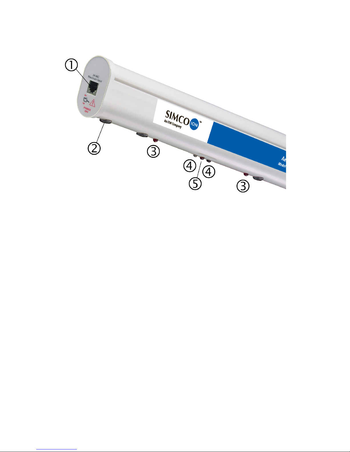
AeroBar Controls and Connectors
Figure 1. AeroBar Model 5225S
(Bar is longer than shown. The number of emitter points will vary per bar.)
1. Modular Port: A modular port on one end of the bar allows a
RJ-11 connection to the 24 VAC power supply for the bar.
2. Emitter Points: Emitters points are replaceable. The number
of points depend on the length of the bar.
3. Positive and Negative Ion Output Indicators: LEDs indicate
high voltage (HV) ionization. In Pulsed DC mode, lights flash
depending on which polarity has HV. Lights are continuously on
when in Steady State mode. Both positive and negative ion indi-
cators and the Alarm LED flash once simultaneously during
communication.
4. Transmit and Receive LEDs: LEDs communicate with an
optional IR remote control.
5. Alarm LED: LED flashes when the AeroBar is in alarm or
standby mode; also flashes once during communication with
the IR remote.
Emitter Points

19-5225S-M-01 Rev 2 4
Emitter points are replaceable. The number of points depends on
the length of the bar.
Indicators
Positive and Negative Ion Output Indicators
These LEDs indicate high voltage (HV) ionization. In pulsed DC
mode, the lights flash depending on which polarity has high voltage.
Lights are continuously on when in steady state DC mode. Both of
the positive and negative ion indicators and the alarm LED flash
once simultaneously during communication.
Transmit and Receive LEDs
These LEDs indicate communication with the Remote Control.
Alarm LED
The red alarm LED flashes when the AeroBar is in alarm or standby
mode; also flashes once during communication with the Remote
Control.
Length of Bar in Inches No. of Emitter Points
22 5
28 7
36 (2-load port configuration) 8
44 9
56 (3-load port configuration) 12
64 13
76 (4-load port configuration) 16
84 17
19-5225S-M-01 Rev 2 5
1.2 Remote Control
The Infrared Remote Control Model 5570 is used to communicate
and set the power and timing parameters. Unlike a typical consumer
remote control, the 5570 features a narrow infrared beam that
prevents communication errors with nearby AeroBars. For best
results, hold the remote control within 18-24 inches of an AeroBar’s
vertical centerline and aim directly at the receive LED of the
AeroBar. When the AeroBar receives transmission from the remote
control, it will flash all three LEDs for one second. Each successive
transmission is indicated with a one-second flash after the last
received transmission.
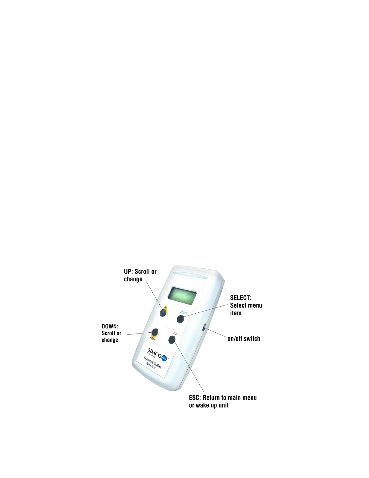
There are four buttons on the Remote Control 5570 (Up, Down,
Select, and Esc).
• The Up and Down buttons are used to scroll through menu
items.
• The Select button selects an item to be changed.
• The Esc button wakes the remote control from sleep mode, or
exits from the activity of a parameter being changed.
Figure 2. Remote Control Buttons

19-5225S-M-01 Rev 2 6
Passwords
The Remote Control features two levels of access: a User Menu
level, and a Technical Field Service (TFS) menu.
• The User Menu level allows you to view current AeroBar
settings, change the operation mode, change the positive and
negative output levels, and set the on times and off times.
• The TFS Menu is password-protected and all basic and
advanced parameters can be changed.
Both the User Menu and TFS Menu feature two lines of information.
The first line displays the item of the menu. The second line displays
the current adjustment level or operation mode for that item.
An on/off slide switch is featured on the right side of the remote
control. Upon powerup, the 5570 remote control shows the
following:
UsrMenu
Ver 2.6
Most menu items of the Remote Control require a password in order
to be changed. The positive and negative output levels of an
AeroBar can be changed without a password. The password is: Esc,
Down, Up, Select, Select, Select, Select.
Sleep Mode
The Remote Control Model 5570 automatically goes into sleep
mode if there is no button activity for 15 seconds. Press the Esc key
to awaken the remote control. While in sleep mode, the LCD
displays:
Use ESC
To Awake
If the battery is low during sleep mode, the bottom line is replaced
with LowBatt.

19-5225S-M-01 Rev 2 7
1.3 Power Requirements
The AeroBar can be powered from any 24 VAC source using one of
the following options:
• Hard wire to a DIN rail mount transformer (p/n 14-21730)
• Connect to DIN rail mount transformer through a junction box
using an RJ-11 to RJ-11 interconnect cable (p/n 33-1700-xx)
• Connect to a 100/115/230 VAC switchable desktop transformer
(p/n 14-1535).

19-5225S-M-01 Rev 2 8

19-5225S-M-01 Rev 2 9
2
Installation
2.1 Mounting
2.2 Wiring
2.3 FMS Connection
2.4 Daisy-chaining

19-5225S-M-01 Rev 2 10
Important Safety Information
Before installing or operating any components, carefully read the
following safety information:
After removing power from the AeroBar(s), allow a minute for
the high voltage power supplies to discharge.
Use proper input voltage to avoid damaging the unit.
Failure to follow these important safety cautions
could result in damage to Digital AeroBar System
components and voiding of your system warranty.

19-5225S-M-01 Rev 2 11
2.1 Mounting
General Guidelines
Installation methods will vary, as all process equipment has
different requirements. Use the following general guidelines:
• Install AeroBars away from all moving components in the tool or
environment.
• Place AeroBars directly in the airflow from HEPA filters for
effective ionization discharge.
• Make sure that there are no obstructions in the airflow between
the AeroBar and the surfaces to be neutralized.
• Ensure there is unobstructed airflow over emitter points.
• Keep emitter points at least 4 inches (100 mm) from grounded
surfaces, including tool frames, skins, and other modules.
• Keep the AeroBars within a 12-36” (300-900 mm) working
distance from the wafers.
Keep in mind the following considerations when determining
locations for the units:
• Tool and mini-environment requirements/restrictions
• Line of sight to infrared LED on the bar
• Applicable SEMI standards
• Applicable National Electrical Code standards
• The least amount of distance for cables from the Interface
Module to AeroBars
Clips
Various mounting clips are available from Simco-Ion.
In general:
• Hold the bar to the grid or other structure and mark the locations
where the mounting clips will attach.
• Attach the clips to the AeroBar and mount them at the marked
locations. Check to make sure all clips are secure, and that the
AeroBar is held firmly in position.

19-5225S-M-01 Rev 2 12
Flat metal clip (p/n 28-6255): Two required for 44” bars; three for
64", 76", and 84" bars.
A polycarobante rod and clip assembly is also available #93-1420
(4”), 93-1421 (8”), 93-1422 (12”)
Mid-clip for hang mount (p/n 28-6240): Use
alone or in conjunction with end clips for bars over
44" in length.
May be used with end clip 28-6235
Grid clip for perforated panels (p/n 28-6257):
Use for bars 44” or shorter.
Requires two pine tree fasteners #28-0505.
Eggcrate mid-clips (p/n 28-6230): Use
alone or in conjunction with end clips for
bars over 44" in length.
Requires eggcrate endclip #28-6225 with
two pine tree fasteners #28-0505.
Mounting Clip Recommendations
Bar Length Number of Clips
22-44 inches (11.8–71.1 cm) 2
56-84 inches (162.6–213.4 cm) 3

19-5225S-M-01 Rev 2 13
2.2 Wiring
The AeroBar may be hard wired directly to 24 VAC line voltage, or
to a 24 VAC transformer. Two 24 VAC transformer options are
available from Simco-Ion:
• 230/240 VAC DIN Rail Mount transformer (p/n 14-21730)
• 100/115/230 VAC switchable desktop transformer (p/n 14-
1535)
Connection to Power
The AeroBar can be directly wired to a 24 VAC source using wire
terminations.
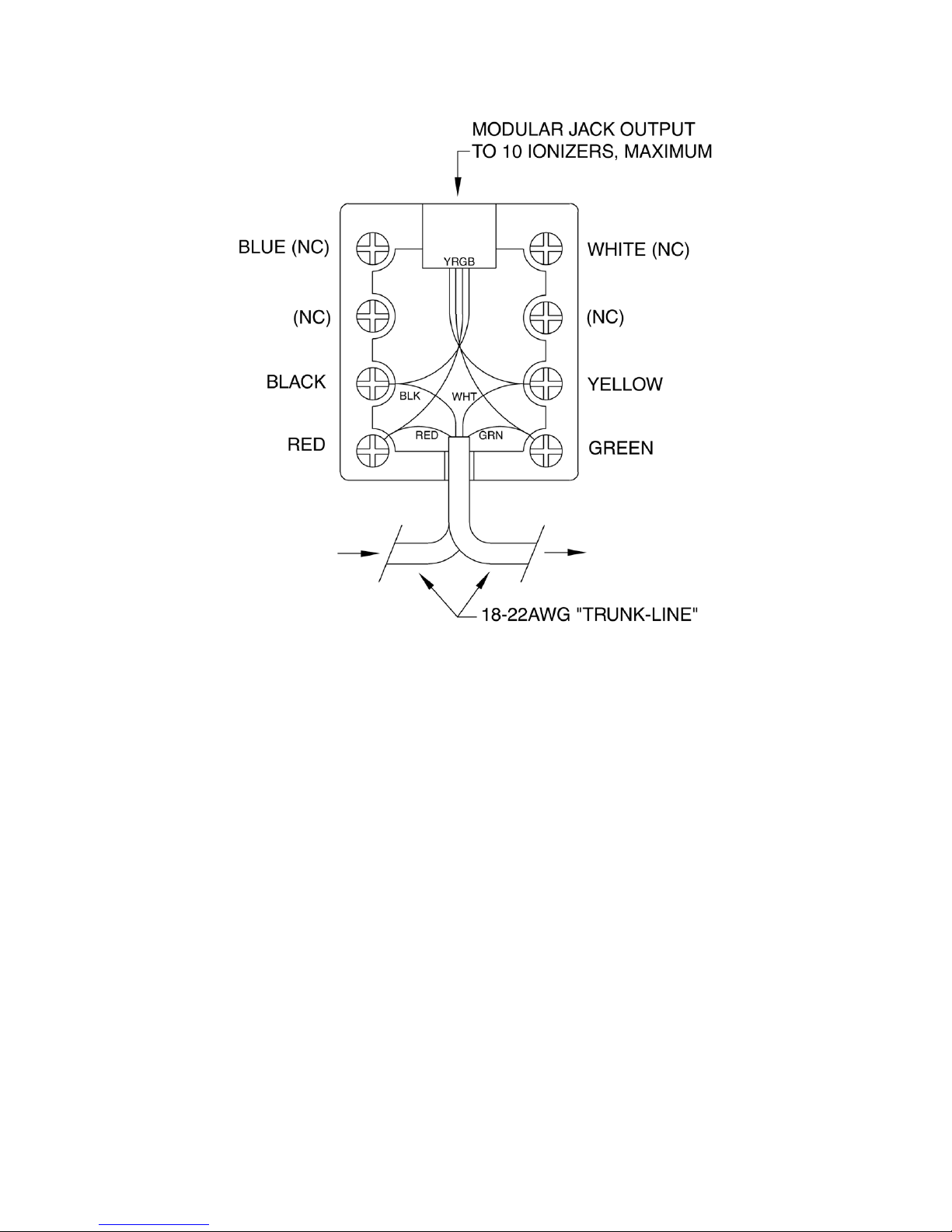
Figure 3. Interconnect Cable Information
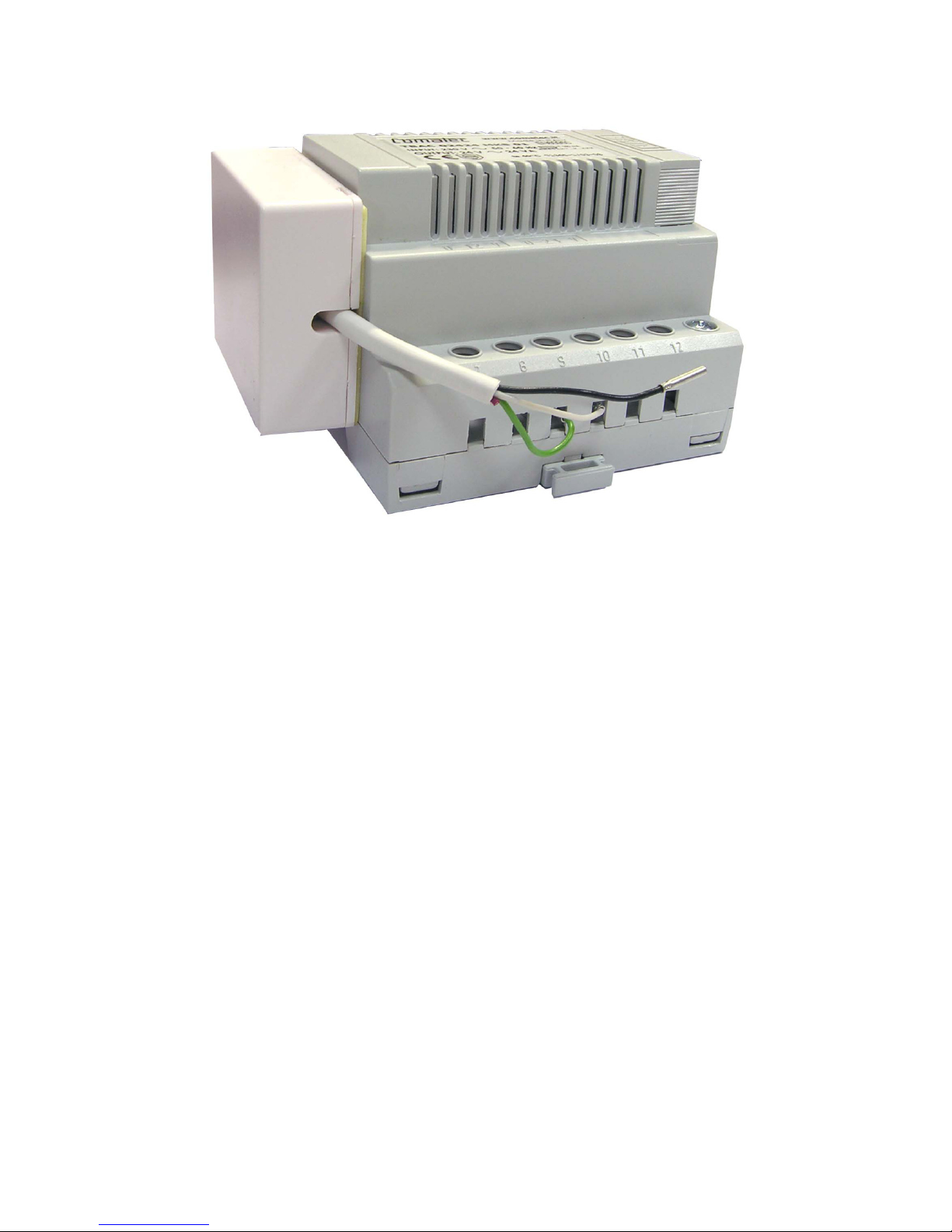
Connection to the DIN Rail Mount Transformer
The interconnect cable can be connected to the DIN Rail mount
transformer (Simco-Ion p/n 14-21730) using either a bare wire

19-5225S-M-01 Rev 2 14
termination or an interconnect cable with an RJ-11 connector to a
Junction Box (p/n 33-1825) wired to the transformer. (An RJ-11
connector is used at the AeroBar.)
Direct Wire
To wire directly to the transformer, use the wiring diagram shown in
the figure below. Connect the 24 VAC and 24 VAC return wires and
cut the unused #3 wire. The Alarm line will be wired to an FMS
connection, if used.
Figure 4. Wiring Interconnect Cable or J-box Directly to the Transformer
J-box Wiring
To use the RJ-11 connector, wire the junction box to the transformer
according to Figure 4 and physically attach it to the side of the
transformer or in close proximity to the transformer. See Figure 7 for
suggested mounting.
19-5225S-M-01 Rev 2 15
Figure 5. J-box Wiring
Contact Simco-Ion for specific information on wiring the j-box
19-5225S-M-01 Rev 2 16
Figure 6. J-box Mounting Suggestion
When using the FMS output connection with the DIN rail mount
transformer, the FMS signal must be wired to the your FMS system
either by direct wire or through a junction box alarm wire.
Connection to the Desktop Transformer
Wiring to the 100/115/230 VAC switchable desktop transformer
(Simco-Ion p/n 14-1535) requires an interconnect cable with an RJ-
11 4-wire connector at the AeroBar end and an RJ-22 4-wire
connector at the transformer end. Pre-made interconnect cables
with these connectors are available from Simco-Ion (p/n 33-1725-
10).
Table of contents


