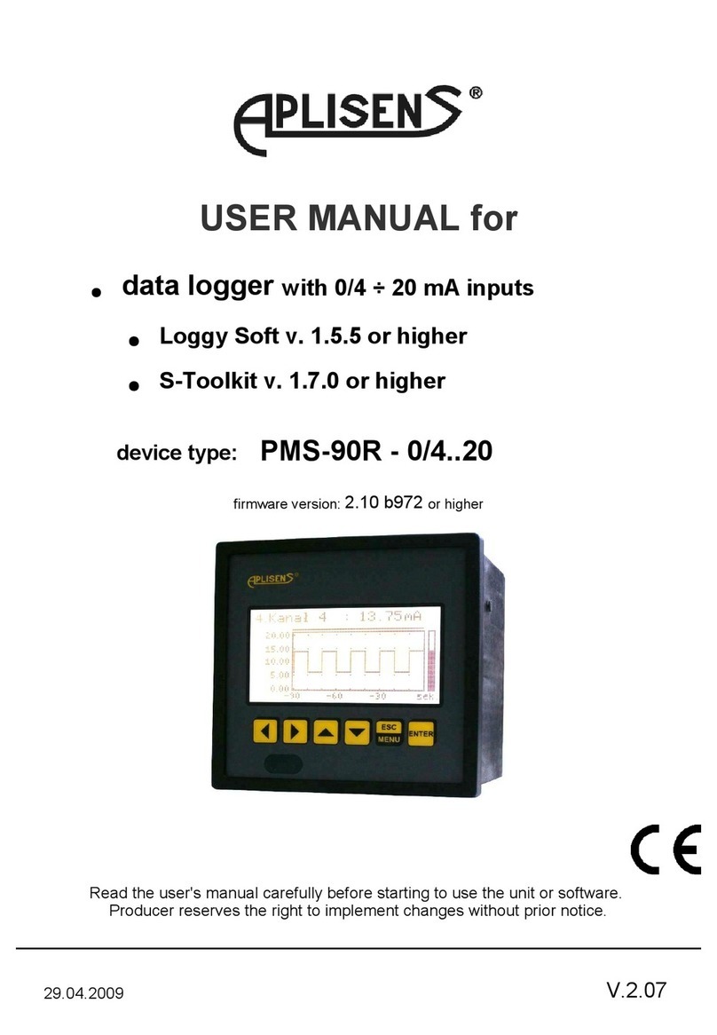
Simex SRD-99 User manual

SIMEX®
USER MANUAL for
●data logger with 0/4 ÷ 20 mA in uts
●Loggy Soft v. 1.5.5 or higher
●S-Toolkit v. 1.7.0 or higher
device ty e: SRD-99 - X100 - 1 - X - XX1
firmware version: 2.10 b972 or higher
Read the user's manual carefully before starting to use the unit or software.
Producer reserves the right to im lement changes without rior notice.
25.08.2008 V.2.06

User manual for Data Logger and cooperating software
CONTENTS
I. USER MANUAL FOR “SRD-99” DATA LOGGER...................................................4
1. BASIC REQUIREMENTS AND USER SAFETY........................................................................................4
2. GENERAL CHARACTERISTICS................................................................................................................5
3. TECHNICAL DATA......................................................................................................................................6
4. DEVICE INSTALLATION............................................................................................................................9
4.1. UNPACKING.......................................................................................................................................9
4.2. ASSEMBLY........................................................................................................................................9
4.3. CONNECTION METHOD.................................................................................................................12
4.4. MAINTENANCE................................................................................................................................15
5. FRONT PANEL DESCRIPTION................................................................................................................16
6. PRINCIPLE OF OPERATION...................................................................................................................17
6.1. MEASUREMENT MODE..................................................................................................................17
6.1.1.Rec rding m mentary and averaged data...............................................................................17
6.2. MODES OF RESULT PRESENTATION..........................................................................................19
6.2.1. "Single channel" m de............................................................................................................20
6.2.2."Measurements list" m de.......................................................................................................22
6.2.3.”Graph” m de...........................................................................................................................24
6.2.4.”Channels List” m de...............................................................................................................27
7. DEVICE PROGRAMMING.........................................................................................................................2
7.1. PARAMETERS EDITION.................................................................................................................30
7.1.1.Numeric and switching parameters ("LIST" - type)..................................................................30
7.1.2. Text parameters......................................................................................................................31
7.1.3.“SLIDER” - type parameters.....................................................................................................32
7.2. DESCRIPTION OF RESULTS PRESENTATION MODES MENU.................................................32
7.2.1."Measurements list pti ns" menu...........................................................................................33
7.2.2.”Graph pti ns” menu..............................................................................................................34
7.2.3.”Channels list pti ns” menu....................................................................................................34
7.3. RESULTS PRESENTATION MODES MENU STRUCTURE..........................................................35
7.4. MAIN MENU DESCRIPTION...........................................................................................................35
7.4.1.”Device inf rmati n” menu.......................................................................................................35
7.4.2.”Display pti ns” menu............................................................................................................36
7.4.3.”L gging setup” menu..............................................................................................................37
7.4.4.”Input settings” menu...............................................................................................................39
7.4.5.”Date & time settings” menu....................................................................................................41
7.4.6.”RS485 p rt settings” menu.....................................................................................................42
7.4.7.”Access setup” menu...............................................................................................................43
7.4.8.”USB pti ns” menu.................................................................................................................44
7.4.9.”Language” parameter..............................................................................................................45
7.5. MAIN MENU STRUCTURE..............................................................................................................46
. DOWNLOADING DATA FROM DATA LOGGER.....................................................................................47
8.1. MODBUS (RS485) DATA DOWNLOAD..........................................................................................47
8.2. USB FLASH DRIVE (PENDRIVE) DATA DOWNLOAD..................................................................47
9. THE MODBUS PROTOCOL HANDLING.................................................................................................4
9.1. LIST OF REGISTERS......................................................................................................................48
9.2. TRANSMISSION ERRORS HANDLING..........................................................................................51
9.3. EXAMPLES OF QUERY/ANSWER FRAMES.................................................................................51
10. USER'S SETTINGS LIST........................................................................................................................55
II. USER MANUAL FOR “LOGGY SOFT”.................................................................59
1. GENERAL CHARACTERISTICS..............................................................................................................59
2. INSTALLATION AND STARTUP..............................................................................................................59
2

User manual for Data Logger and cooperating software
3. USING THE PROGRAM............................................................................................................................62
3.1. „CURRENT MEASURE” MENU.......................................................................................................63
3.2. „REPORTS” MENU..........................................................................................................................63
3.2.1.„Table” tab................................................................................................................................64
3.2.2.„Graph” tab...............................................................................................................................66
3.3. „CONFIGURATION” MENU.............................................................................................................71
3.3.1.„Devices” tab............................................................................................................................71
3.3.2.„Gr ups” tab - gr up perati ns...............................................................................................73
3.3.3.„Settings” tab............................................................................................................................75
3.4. LIST OF ERRORS AND FAULT DIAGNOSTICS ...........................................................................76
III. USER MANUAL FOR “S-TOOLKIT”....................................................................77
1. GENERAL CHARACTERISTICS..............................................................................................................77
2. INSTALLATION AND STARTUP..............................................................................................................77
3. USING PROGRAM....................................................................................................................................7
3.1. “INPUTS SETTINGS” TAB...............................................................................................................79
3.2. “LOGGING SETUP” TAB.................................................................................................................80
3.3. “INTERFACE OPTIONS” TAB........................................................................................................81
3.4. “DEVICE INFORMATION” TAB.......................................................................................................82
3.5. CONFIGURATION MODES.............................................................................................................83
3.5.1.Individual c nfigurati n f channels.........................................................................................83
3.5.2.C nfiguring selected channels.................................................................................................83
3.5.3.C nfiguring all channels...........................................................................................................83
3.6. UPDATING SOFTWARE OF SRD-99 DEVICE...............................................................................84
Explanation of symbols used in the manual:
- This symb l den tes especially imp rtant guidelines c ncerning the installati n and
perati n f the device. N t c mplying with the guidelines den ted by this symb l
may cause an accident, damage r equipment destructi n.
IF THE DEVICE IS NOT USED ACCORDING TO THE MANUAL THE USER IS
RESPONSIBLE FOR POSSIBLE DAMAGES.
- This symb l den tes especially imp rtant characteristics f the unit.
Read any inf rmati n regarding this symb l carefully
3
i
!

User manual for Data Logger and cooperating software
I. USER MANUAL FOR “ SRD-99 ” DATA LOGGER
1. BASIC REQUIREMENTS AND USER SAFETY
- The manufacturer is not res onsible for any damages caused by
ina ro riate installation, not maintaining the ro er technical condition
and using the unit against its destination.
- Installation should be conducted by qualified ersonnel . During installation all
available safety requirements should be considered. The fitter is res onsible for
executing the installation according to this manual, local safety and EMC
regulations.
- The unit must be ro erly set-u , according to the a lication. Incorrect
configuration can cause defective o eration, which can lead to unit damage or
an accident.
- If in the case of a defect of unit o eration there is a risk of a serious threat
to the safety of eo le or ro erty additional, inde endent systems and
solutions to revent such a threat must be used.
- The unit uses dangerous voltage that can cause a lethal accident. The unit
must be switched off and disconnected from the ower su ly rior to
starting installation of troubleshooting (in the case of malfunction).
- Neighbouring and mating equi ment must meet the requirements of a ro riate
standards and regulations concerning safety and be equi ed with adequate
anti-overvoltage and anti-interference filters.
- Do not attem t to disassemble, re air or modify the unit yourself. The unit
has no user serviceable arts. Units, in which a defect was stated must be
disconnected and submitted for re airs at an authorized service centre.
- In order to minimize fire or electric shock hazard, the unit must be rotected
against atmos heric reci itation and excessive humidity.
- Do not use the unit in areas threatened with excessive shocks, vibrations, dust,
humidity, corrosive gasses and oils.
- Do not use the unit in ex losion hazard areas.
- Do not use the unit in areas with significant tem erature variations, ex osed to
condensation or icing.
- Do not use the unit in areas ex osed to direct sunlight.
- Make sure that the ambient tem erature (e.g. inside the control box) does not
exceed the recommended values. In such cases forced cooling of the unit must
be considered (e.g. by using a ventilator).
The unit is designed for o eration in an industrial environment and must
not be used in a household environment or similar.
4
!
!
!

User manual for Data Logger and cooperating software
2. GENERAL CHARACTERISTICS
• Multifunctional
SRD-99 designed for recording, dis laying current or averaged values and
resentation of technological arameter trends in gra hic form. All measured
arameters must be available in 0-20 mA or 4-20 mA (this can be for exam le
ressures, levels, humidity, tem eratures, forces, etc.).
• Large data storage capacity
The registered measurement results are recorded in the unit's memory. The
ca acity of installed memory allows to store:
–over 500 000 measurements (2MB) for units equi ed with RS485 interface
–over 2 000 000 measurements (8MB) for units equi ed with RS485 interface
and USB Host ort.
• Configurable measurement and control input
The unit has u to 8 channels of 0-20 mA (4-20 mA) current signals and one digital
voltage in ut with rogrammable functions, e.g. control of the recording rocess.
Each signal can be freely configured and described. The internal analogue-digital
converter has a 12 bit resolution, which rovides high recording resolution results.
Additionally, individual al hanumeric descri tion (text) of each of the recorded
channels is ossible.
• Fast serial interface
The data recorder is fitted with a galvanic insulated RS 485 interface, rogrammed
with ModBus RTU transmission rotocol. This enables the connection of a number
of data recorders into the network, remote collecting of data from each unit and also
remote configuration. The a lication of the RS 485 interface instead of RS 232 is
due to the ossibility of achieving high transmission s eeds using transmission lines
of larger length than is ossible with the RS 232 interface.
• Built-in USB Host interface (optional)
O tionally the data logger can be equi ed with built-in USB Host interface,
allowing for data transfer to o ular USB Flash Drives (PenDrives). This method
allows for significant sim lification of unit a lication: it is no longer necessary to
connect PC and SRD-99 via RS-485 interface.
Significant acceleration of data transfer is an additional advantage: data download
can be 10 times faster than using RS-485 interface.
WARNING! SRD-99 should work ro erly with any standard Flash Drives, but
manufacturer can not guarantee ro er coo eration with non-standard devices, or
with devices develo ed after SRD-99 release.
5

User manual for Data Logger and cooperating software
• Wide range of power supply voltage and external sensor power supply
The built-in ulse ower su ly allows ower to be su lied to the unit with
85...230...260V AC/DC voltage or 16...24...35 AC, 19...24...50 DC voltage
(de ending on version). The voltage for owering the sensor and converters is
connected to the rear terminal stri : 24V DC ±5% / max. 200mA.
• Legible graphic display
The 128 x 64 oints dis lay with a backlight mounted on front of the unit is a big
advantage of the data recorder. It allows the dis lay of trend gra hs for each
channel se arately. Different o eration modes rovide the ossibility of selecting
and adjusting the method of data resentation de ending on the user's
requirements. Data recording intervals are selected by the user from the menu
level. Additionally, it is ossible to set the dis lay to show one current value
measured for a selected channel.
• Easy configuration
There are 6 keys on the front of the data recorder that enable the configuration of
the unit. The menu assisted with full text descri tions makes the unit configuration
rocess quite easy. However, due to a significant number of configured arameters
it is advised to use the attached configuration software for PCs.
3. TECHNICAL DATA
Power su ly voltage
(de ending on version)
External Fuse (required)
Power consum tion
85...230...260V AC/DC; 50 ÷ 60 Hz
or 19...24...50V DC; 16V...24...35V AC
T - ty e, max. 2 A
ty ically 7 VA; max. 12 VA
In uts
Measurement:
Digital:
u to 8 in uts 0-20 mA or 4-20 mA, common ground
1 in ut 24V DC, galvanic insulation
ower consum tion: 7,5 mA / 24V,
insulation: 1min @ 500V DC.
Sensor ower su ly out ut 24V DC ± 5% / max. 200 mA,
Not insulated from measurement in uts
Measurement range ± 9999 lus decimal oint
Current measurement accuracy ± 0,25% ± one digit (for 0-20 mA range)
Acce ted rolonged in ut overload: 20%
Measurement in ut resistance 100 Ω
Communication interface
Baud rate
RS 485, 8N1 / Modbus RTU, not se arated
1200 bit/s ÷ 115200 bit/s
USB Host interface (o tional) Coo eration with standard Flash Disks (USB 2.0)
6

User manual for Data Logger and cooperating software
Dis lay
Data memory
LCD gra hic dis lay, 128 x 64 oints, with backlight
2MB - version without USB Host
8MB - version with USB Host interface
Protection level
version without USB interface IP 65 (from front, after using water roof cover)
IP 40 (from front)
IP 20 (housing and connection cli s)
version with USB interface IP 42 (from front, after using water roof cover)
IP 20 (housing and connection cli s)
Housing ty e
Housing material
Housing dimensions
Mounting hole
Assembly de th
Panel thickness
anel
NORYL - GFN2S E1
96 x 96 x 100 mm
90,5 x 90,5 mm
102 mm
max. 5 mm
O erating tem erature
Storage tem erature
Humidity
Altitude
0°C to +50°C
-10°C to +70°C
5 to 90% no condensation
u to 2000 meters above sea level
Screws tightening max. torque 0,5 Nm
Max. connection leads diameter 2,5 mm2
Safety requirements according to: PN-EN 61010-1
installation category: II
ollution degree: 2
voltage in relation to ground: 300V AC
insulation resistance: >20MΩ
insulation strength between ower su ly and
in ut/out ut terminal: 1min. @ 2300V (see Fig. 3.1)
EMC PN-EN 61326
Software (Wind ws envir nment)
•S-Toolkit, PC software for data logger easy configuring,
•Loggy Soft, PC software for moving, re orting, archiving and dis laying recorded data.
This is a class A unit. In housing or a similar area it can cause radio
frequency interference. In such cases the user can be requested to use
a ro riate reventive measures.
Carefully check that the insulation used with the unit (Fig. 3.1) meets the
ex ectations and if necessary use a ro riate measures of overvoltage rotection.
Additionally, assure the maintenance of a ro riate installation air and surface
insulation ga s (Tab. 3.1).
7
!
!

User manual for Data Logger and cooperating software
Range of operating voltage Air gap [mm] Surface gap [mm]
U to 50V RMS or DC 0,2 1,2
U to 100V RMS or DC 0,2 1,4
U to 150V RMS or DC 0,5 1,6
U to 300V RMS or DC 1,5 3,0
Tab. 3.1. Minimal insulati n gaps acc rding t EN 61010-1
Fig. 3.1. Schematic diagram sh wing the insulati n between individual circuits f the unit.
8
Internal circuits
relay 2
relay 1
External sensor
su ly out ut
Measurement in uts RS 485
interface
Insulation strength 1min @ 2300V AC
Insulation strength 1min @ 1350V AC
Insulation strength 1min @ 500V AC
No insulation
Relay circuits
Power su ly

User manual for Data Logger and cooperating software
4. DEVICE INSTALLATION
The unit has been designed and manufactured in a way assuring a high level of user
safety and resistance to interference occurring in a ty ical industrial environment. In order to
take full advantage of these characteristics installation of the unit must be conducted correctly
and according to the local regulations.
- Read the basic safety requirements on age 4 rior to starting the installation.
- Ensure that the ower su ly network voltage corres onds to the nominal
voltage stated on the unit’s identification label.
- The load must corres ond to the requirements listed in the technical data.
- All installation works must be conducted with a disconnected ower su ly.
- Protecting the ower su ly clam s against unauthorized ersons must be
taken into consideration.
4.1. UNPACKING
After removing the unit from the rotective ackaging, check for trans ortation damage.
Any trans ortation damage must be immediately re orted to the carrier. Also, write down the
unit serial number on the housing and re ort the damage to the manufacturer.
Attached with the unit lease find:
–assembly brackets - 2 ieces,
–warranty,
–user’s manual for SRD-99 unit (device)
–user’s manuals for coo erating software,
–CD-ROM with the aforesaid manual in PDF format and installation files of coo erating
software.
4.2. ASSEMBLY
- The unit is designed for mounting indoor inside housings (control anel,
switchboard) assuring a ro riate rotection against electric im ulse waves.
Metal housing must be connected to the grounding in a way com lying with the
governing regulations.
- Disconnect the ower su ly rior to starting assembly.
- Check the correctness of the erformed connections rior to switching the unit
on.
9
!
!

User manual for Data Logger and cooperating software
In order to assembly the unit, a 90,5 x 90,5 mm mounting hole (Fig. 4.1) must be
re ared. The thickness of the material of which the anel is made must not exceed
5mm. When re aring the mounting hole take the grooves for catches located on
both sides of the housing into consideration (Fig. 4.1). Place the unit in the
mounting hole inserting it from the front side of the anel, and then fix it using the
brackets (). The minimum distances between assembly holes’ axes - due to the
thermal and mechanical conditions of o eration - are 115 mm x 115 mm (Fig. 4.4).
Fig. 4.1. M unting h le dimensi ns
Fig. 4.2. Installing f brackets, and dimensi ns f c nnect rs.
10
90,5 mm
13 mm
8 mm
8 mm
13 mm
1 mm max. 5 mm
90,5 mm
1 mm
92 mm
5 mm 12 mm 10 mm
8,5 mm
16 mm

User manual for Data Logger and cooperating software
4.3. CONNECTION METHOD
Caution
- Installation should be conducted by qualified ersonnel . During installation all
available safety requirements should be considered. The fitter is res onsible for
executing the installation according to this manual, local safety and EMC
regulations.
- The unit is not equi ed with an internal fuse or ower su ly circuit breaker.
Because of this an external time-delay cut-out fuse with minimal ossible nominal
current value must be used (recommended bi olar, max. 2A) and a ower su ly
circuit-breaker located near the unit. In the case of using a mono olar fuse it must
be mounted on the hase cable (L).
- The ower su ly network cable diameter must be selected in such a way that in
the case of a short circuit of the cable from the side of the unit the cable shall be
rotected against destruction with an electrical installation fuse.
- Wiring must meet a ro riate standards and local regulations and laws.
- In order to secure against accidental short circuit the connection cables must be
terminated with a ro riate insulated cable ti s.
- Tighten the clam ing screws. The recommended tightening torque is 0.5 Nm.
Loose screws can cause fire or defective o eration. Over tightening can lead to
damaging the connections inside the units and breaking the thread.
- In the case of the unit being fitted with se arable clam s they should be inserted
into a ro riate connectors in the unit, even if they are not used for any
connections.
- Unused clam s (marked as n.c.) must not be used for connecting any
connecting cables (e.g. as bridges), because this can cause damage to the
equi ment or electric shock.
- If the unit is equi ed with housing, covers and sealing acking, rotecting
against water intrusion, ay s ecial attention to their correct tightening or clam ing.
In the case of any doubt consider using additional reventive measures (covers,
roofing, seals, etc.). Carelessly executed assembly can increase the risk of electric
shock.
- After the installation is com leted do not touch the unit’s connections when it is
switched on, because it carries the risk of electrical shock.
Due to ossible significant interference in industrial installations a ro riate measures
assuring correct o eration of the unit must be a lied. To avoid the unit of im ro er
indications kee recommendations listed below.
-Avoid common ( arallel) leading of signal cables and transmission cables together with
ower su ly cables and cables controlling induction loads (e.g. contactors). Such cables
should cross at a right angle.
-Contactor coils and induction loads should be equi ed with anti-interference rotection
systems, e.g. RC-ty e.
12
!

User manual for Data Logger and cooperating software
-Use of screened signal cables is recommended. Signal cable screens should be
connected to the earthing only at one of the ends of the screened cable.
-In the case of magnetically induced interference the use of twisted cou les of signal
cables (so-called “s irals”) is recommended. The s iral (best if shielded) must be used
with RS-485 serial transmission connections.
-In the case of interference from the ower su ly side the use of a ro riate anti-
interference filters is recommended. Bear in mind that the connection between the filter
and the unit should be as short as ossible and the metal housing of the filter must be
connected to the earthing with largest ossible surface. The cables connected to the filter
out ut must not run in arallel with cables with interference (e.g. circuits controlling relays
or contactors).
Connections of ower su ly voltage and measurement signals are executed using the
screw connections on the back of the unit’s housing.
Fig. 4.5. Meth d f cable insulati n replacing and cable terminals dimensi ns
All connections must be made while ower su ly is disconnected !
Fig. 4.6. Terminals descripti n
13
1 2
22 23 24 25 26
34 35 36 37 38
Power su ly
(de ending on version) GND- RS
DATA+
DATA-
18 19 20 21
33
n.c.
28 29 30 31 3227
15 16 17
AGND
AIN8
AIN7
AIN6
AIN5
AIN4
AIN3
AIN2
AIN1
GND
+24V
GND
10 11 12 13 149
+24V
additional terminals
(internally connected)
current in uts
RS 485
Warning!
GND and AGND
internally connected
DIN+DIN-
digital in ut
!
6-7 mm
max. 2 mm

User manual for Data Logger and cooperating software
Depending n versi n:
85...230...260V AC/DC r
19...24...50V DC; 16...24...35V AC
Fig. 4.7. C nnecti n f p wer supply
Fig. 4.8. C nnecti ns f current signals f active sens rs
(current signal 0-20 mA r 4-20 mA and gr und)
Fig. 4.9. C nnecti ns f current signals f 2-wire sens rs
(sens r p wer supply v ltage and 4-20 mA signal)
14
additional terminals
(internally connected)
22 23 24 25 26
34 35 36 37 38
18 19 20 21
3328 29 30 31 3227
15 16 17
GND
AGND
external
GND
connection
in ut 1
4-20mA
in ut 8
4-20mA
. . . . .
additional terminals
(internally connected)
22 23 24 25 26
34 35 36 37 38
18 19 20 21
3328 29 30 31 3227
15 16 17
GND
external
GND
connection
. . . . .
+
AGND
+
to sensor to sensor
external
sensor
su ly
connection
+24V
sensor
su ly
out ut
GND
+24V
sensor
su ly
out ut
!
FUSE
1 2
L N
N
L

User manual for Data Logger and cooperating software
Fig. 4.10. C nnecti n f digital input (depending n data rec rder c nfigurati n)
Fig. 4.11. C nnecti n f RS-485 transmissi n signals
The SRD-99 device su orts the following converters:
–USB / RS-485 converter (SRS-USB/4-Z45)
–RS-232 / RS-485 converter (SRS-2/4-Z45)
4.4. MAINTENANCE
The unit does not have any internal re laceable or adjustable com onents available to
the user. Pay attention to the ambient tem erature in the room where the unit is o erating.
Excessively high tem eratures cause faster ageing of the internal com onents and shorten the
fault-free time of unit o eration.
In cases where the unit gets dirty do not clean with solvents. For cleaning use warm water with
small amount of detergent or in the case of more significant contamination ethyl or iso ro yl
alcohol.
Using any other agents can cause ermanent damage to the housing.
Product marked with this symbol should not be laced in munici al waste. Please
check local regulations for dis osal and electronic roducts.
15
12 13
RS 485
DATA-
GND-RS
14
DATA+
RS232/485
interface
-+
!
9 10
24 V DC recording enable
external switch
external
su ly
digital
in ut
DIN- DIN+

User manual for Data Logger and cooperating software
5. FRONT PANEL DESCRIPTION
Key designation and functions
Symbols used in the manual: [ESC/MENU] and
Functions:
• go to main menu ( ress and hold by at least 2 sec.),
• go to result resentation modes menu,
• exit the current level and return to revious menu (or to one of result
resentation modes),
• cancellation of changing the edited data logger arameter.
Symbols used in the manual: [ENTER] and
Functions:
• start editing arameter,
• go to submenu,
• confirm change of edited arameter.
Symbols used in the manual: [<] [>] and
Functions:
• change the horizontal cursor osition,
• modify edited data logger arameter
• change of channel number in one of four result resentation modes and
during measurement channel configuration.
Symbols used in the manual: [^] [v] and
Functions:
• change the vertical cursor osition,
• modify edited data logger arameter,
• change of channel result resentation mode.
16
display
pr gramming
pushbutt ns
MENU
ESC
ENTER
MENU
ESC
ENTER

User manual for Data Logger and cooperating software
6. PRINCIPLE OF OPERATION
After turning the ower su ly on, the logo and basic unit data are showed on the
dis lay, then the unit goes to the measurement mode.
6.1. MEASUREMENT MODE
In the measurement mode the unit executes the measurement of values of signals
connected to current in uts, hereafter called measurement channels (the number of available
channels de ends on the unit version). Measurements are conducted at the frequency of
8 times er second for each channel. The nominal range of in ut current for each in ut is
0-20 mA or 4-20 mA and can be extended to the maximum of 0-22 mA, inde endently to each
measurement channel. The results of the conducted measurements are shown on the LCD
dis lay. The unit com utes the measurement results into indicated values ro ortionally
(linear). The range of measurement results corres onding to the nominal range of in ut
current is defined as nominal measurement range. The range of measurement results
corres onding to the range of in ut current including the extensions is defined as allowable
measurement range (Fig. 6.1).
* "Lower ext." arameter is only significant for an in ut current range of 4-20 mA.
Fig. 6.1. Definiti n f measurement ranges
The range of dis layed values, unit of measured value and osition of the decimal oint
(for resentation in numeric form) are defined by the user.
All available arameters of the unit’s o eration can be configured in the main menu (see
DEVICE PROGRAMMING) or using the RS 485 interface and software installed on your PC.
Configuration of the device (via menu or RS 485 interface) do not sto s the data
recording rocess .
Results of measurements conducted for active (selected by the user) channels of the unit are
dis layed in one of the available result resentation modes (see RESULT PRESENTATION
MODES).
6.1.1. Recording momentary and averaged data
17
i
nominal measurement range
”Hi value” arameter
”Lo value” arameter
ermissible measurement range
”Lower ext.” arameter ”Higher ext.” arameter

User manual for Data Logger and cooperating software
Values corres onding to the results of current measurement conducted for each channel can
be recorded (stored in the non-volatile memory of the unit) for further analysis. The recording
of measurement results for all channels is erformed with the same frequency, defined by the
user in the range between 1 record er second to 1 record er hour ("Rec. eriod"
arameter). Recording times are synchronized with the internal real time clock. Recording can
be sto ed at any moment with selected status on digital in ut of the unit ("Triggering"
arameter).
In order to enable more advanced mathematical rocessing of recorded signals it is
ossible to set the unit's o tions to record averaged measurement results. Setting the
recorded value ty e to averaged value ( arameters "Channel 1"... "Channel 8", de ending
on the number of channels in the unit) causes that instead of momentary values the unit
records in its memory values that constitute the average results of measurements conducted
during the set recording period. All measurements conducted by the unit shall be averaged
(eight measurements er second), irres ective of the set recording frequency.
The rinci le of recording measurements is resented in figure 6.2. In the case of recording
momentary values t(a), t(b), t(c) designate the recording times of values corres onding to
current measurements an, bn, cn. In the case of recording averaged values t(a), t(b), t(c)
designate the times of recording values corres onding to measurement averaging results,
a1…an, b1…bn, c1…cn corres ondingly.
Ex lanation :
t(a), t(b), t(c) - recording oints
a, b, c, d - measurement oints
Δt - delay between measurements (0.125s)
Fig. 6.2. Principle f measurement rec rding
Averaging o eration concerns only the ty e of recorded values; it does not concern
the method of resentation of current measurement. In all result resentation modes,
indications - described in the remaining art of the manual as results of
measurements not recorded in the unit's memory - corres ond to the momentary
value of the measured signal.
Averaged values can be viewed in the data logger only in the "Measurements list" and
"Gra h" results resentation mode, because these modes enable resentation of values
recorded in the unit's memory. Averaged values can also be viewed in the database
downloaded by the software working with the data logger.
In the case of multi le changes of ty e of recorded value (momentary values of
averaged values) there is no ossibility to distinguish whether data recorded in the
memory concerns momentary measurement value or averaged measurement results.
18
i
i
”Rec. eriod” arameter ”Rec. eriod” arameter
t(a) t(c)
t(b)
an-1 anb1b2b3bnc1c2c3cnd1d2
. . . . . .
Δt

User manual for Data Logger and cooperating software
Recording the measurement results in the non-volatile memory can be executed in two modes:
"until full" or "cyclic" ("Write" arameter). The first mode enables the recording of such
amounts of data as the unit's memory allows for, then the recording is sto ed. In the second
mode, once the memory is full, the results are recorded from the starting address in the
memory, overwriting existing measurement results. The time remaining until the memory is full
is dis layed once the unit is started and in the "Device information" menu, available in the
units main menu.
In the case of both modes, once the memory is full, a warning message is dis layed (see
descri tion of "Write" arameter in the "Logging setu " menu). The recorded data should be
eriodically downloaded to a PC using a ro riate software or alternatively using USB
FlashDrive (method recommended for data loggers equi ed with 8MB of memory).
All arameters concerning the recording mode, the influence of digital in ut on the
recording method, the recording frequency and ty e of recorded value are available in the
"Logging setu " menu described in section MAIN MENU DESCRIPTION.
6.2. MODES OF RESULT PRESENTATION
The results of measurements conducted for active channels are resented in numeric or
gra hic (gra h or bar) form. Selection of one of the available results resentation modes can
be made using the [^] and [v] keys in the measurement mode. Configuration of the method of
dis laying in the selected results resentation mode can be made in the menu of the given
resentation mode (see DESCRIPTION OF RESULTS PRESENTATION MODES MENU). The
following resentation modes are available:
19

User manual for Data Logger and cooperating software
- "Single channel" mode (Fig. 6.3) enables the last
measurement for one of the measurement channels to be
viewed in the numeric and gra hic form (bar).
Fig. 6.3. "Single channel" mode
- "Measurements list" mode (Fig. 6.4) enables the
momentary values recorded during the set eriod of time
or averaged values of the conducted measurements for
one of the measurement channels to be viewed in numeric
form.
Fig. 6.4. "Measurements list" mode
- "Graph" mode (Fig. 6.5) enables the momentary values
or averaged values of measurements conducted for one of
measurement channels to be viewed in the form of a
gra h.
Fig. 6.5. "graph" mode
- "Channels list" mode (Fig. 6.6, 6.7) enables the
measurement results for all active measurement channels
to be viewed in numeric or gra hic (bar) form.
Fig. 6.6. "Channels list" mode (values)
Fig. 6.7. "Channels list" mode (bars)
After starting the unit the result resentation mode and channel selected rior to
switching off the unit are active (this information is stored in the EEPROM memory)
6.2.1. "Single channel" mode
This mode (Fig. 6.8) dis lays the result of the last measurement for one of the active
channels in numeric form (in the middle art of the dis lay) and in the form of a bar
( ercentage, at the bottom of the screen). The gra hical indicator (bar) always shows the
relation of the measurement result to the nominal measurement range (see descri tion of
20
i
Other manuals for SRD-99
1
Table of contents
Other Simex Data Logger manuals


