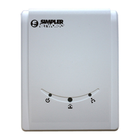
Simpler Networks HP200PT64 User manual

HomePlug AV Ethernet Adapter User’s Manual
Rev
.
1.0
Nov. 2009
HomePlug AV
Powerline Pass-through Ethernet Adapter
User’s Manual
HP200PT
64

HomePlug AV Ethernet Adapter User’s Manual
Table of Contents
1.
INTRODUCTION .......................................................................................................... 1
1.1
G
ENERAL
F
EATURES
............................................................................................... 1
1.2
P
ACKAGE
C
ONTENTS
.............................................................................................. 1
1.3
S
YSTEM
R
EQUIREMENT
........................................................................................... 1
2.
HOMEPLUG A ETHERNET ADAPTER O ER IEW .................................................. 2
2.1
AC
P
OWER
S
OCKET
............................................................................................... 2
2.2
LED
D
ESCRIPTION
.................................................................................................. 2
2.3
P
USH
B
UTTON
/R
ESET HOLE
..................................................................................... 3
2.4
I
NSTALLING YOUR
H
OME
P
LUG
AV
E
THERNET
A
DAPTERS
............................................ 3
2.5
F
ORMING A
H
OME
P
LUG
AV
L
OGICAL
N
ETWORK
......................................................... 4
2.
J
OINING
&
LEAVING THE
P
OWERLINE NETWORK
.......................................................... 5
3.
INSTALLING POWER PACKET UTILITY ..................................................................... 6
4.
USING POWER PACKET UTILITY ............................................................................... 7
4.1
U
SER
I
NTERFACE
.................................................................................................... 7
4.1.1
Main Tab .......................................................................................................... 7
4.1.2
Pri acy Tab ...................................................................................................... 9
4.1.3
Diagnostics Tab .............................................................................................. 10
4.1.4
About Tab....................................................................................................... 11
4.1.5
Preferences .................................................................................................... 11
5.
TROUBLE SHOOTING ............................................................................................... 12
5.1.1
The Power LED does not turn on after plug into power outlet .......................... 12
5.1.2
The LNK LED does not turn on or not flashing ................................................ 12
5.1.3
The Ethernet LED does not turn on ................................................................. 12
5.1.4
No any HP200PT64 de ice be displayed on Power Packet Utility.................... 12
6.
APPENDIX A. SPECIFICATIONS ............................................................................... 13
7.
APPENDIX B. POWERLINE NETWORK APPLICATION ........................................... 14

HomePlug AV Ethernet Adapter User’s Manual
Important Safety Notice:
This device is not for outdoor use that may cause the risk of electric
shock from lightning
.
Do not use this device near the water like swimming pool,
wet environment.
Do not use liquid /aerosol cleaner to clean this device and must unplug
this product before cleaning.
Do not open the cover of device when plug into power socket. These
expose you to the risk of high voltage damage.
Do not put any other things into/on this device especially sharp
conductive object.
Do not open or remove this Powerline Ethernet Adapter case personally,
it may result in exposure to dangerous voltage points or other risks

HomePlug AV Ethernet Adapter User’s Manual
1
1. Introduction
The HP200PT 4 HomePlug AV Powerline Ethernet Adapter (called HP200PT64, hereafter)
provides the fast data and video transmission through your existing Powerline environment.
It’s simple to plug into your power socket to every room in your home and easy to extend your
network without any extra wires and configuration. The integrated female power socket with
AC filter design is convenience of not losing your single power outlet. HP200PT 4 provides
high speed transmit data rates of up to 200Mbps and the QoS support let you enjoy the HD
videos, IPTV /VoIP services, online game and other multimedia contents transmission
smoothly. The built-in AES-128 bit data encryption algorithms can achieve a secure and
safety Powerline network. HP200PT 4 enable you to a high speed home networking
experience!.
1.1 General Features
High speed transfer PHY rate up to 200 Mbps for HD/IPTV and VOD services and whole
triple-play connectivity.
Easy to build or extend home networking environment use the existing power outlet, no
extra wire required.
Simple plug-and-play and zero configuration between the routers, computers, and your
gaming console.
Integrated Quality of Service (QoS) and low power consumption.
128-bit AES data encryption algorithm.
Co-existence with HomePlug 1.0 nodes.
Integrated AC Power Socket with AC filter design.
1.2 Package Contents
2 x HP200PT 4 HomePlug AV Powerline Ethernet Adapters. (dual pack)
2 x Ethernet RJ-45 Cat5.Cables.
1 x Printed Quick Start Guide.
1 x CD-ROM. (Contains Power Packet utility software / User’s Manual / Quick start guide )
1.3 System Requirement
In order to use the HomePlug AV Ethernet Adapters to establish the network connection in
your home, you must have the following:
ADSL or Cable service with at least one public Internet address for your LAN
if you want to use Powerline devices to get on to the internet.
One or more computers each containing an Ethernet network interface card (NIC)
Operating system:
Windows 98/SE,Me,2000,XP,Vista for install/configure/remove Power Packet utility.

HomePlug AV Ethernet Adapter User’s Manual
2
2. HomePlug A Ethernet Adapter Overview
2.1 AC Power Socket
This AC power socket with AC filter built-in design of HP200PT 4
enables additional terminal devices or multiple sockets to be
connected to this device just as a normal wall socket and no power
supply is lost. It has two earthing clips on the sides of the plug instead
of a female earth contact and supplies up to 1 Amperes that
connected with other electrically operated power device.
2.2 LED Description
The front bottom side contains 3 lights called LEDs that indicate the status of this device:
LED
Color
Status
Description
Off This Adapter is not connected to power
Flashing evenly at
1 second interval
(Dark Red)
This Adapter is in
Power Saving
mode if there is no link on
Ethernet for 10 seconds.
After the link on Ethernet is active, the adapter wakes up
automatically.
Flashing evenly at
1 second interval (Green)
The adapter is in configuration mode, an AVLN is being
formed (new AVLAN is formed or a new adapter is being
added to an existing AVLN).
Uneven flashing There was error during configuration process
Green The adapter is connected to power
Off There is no link on Powerline interface
Red If Powerline link present, Estimated application Throughput <
Low Threshold ※
Orange If Powerline link present, Low Threshold ≤ Estimated
application Throughput < High Threshold
Green If Powerline link present, Estimated application-Throughput ≥
High Threshold
Off
There is no Ethernet Cable connected to the adapter
Green
There is link on Ethernet interface
Green flash
There is activity on Ethernet interface
Function
※Threshold default Low Threshold:20Mbps; default High Threshold:40Mbps
Factory Default press RESET button for 3~5 sec
NMK
randomization Press NMK button for 10 sec. Finish when all LEDs are OFF and ON again.
❶
❷
❸
❶
❷
❸

HomePlug AV Ethernet Adapter User’s Manual
3
2.3 Push Button/Reset hole
The right-hand side on the device contains the push button and reset hole for the easy data
encryption/synchronization and reset to the default factory’ settings: .
NMK (Network Membership Key) button
Implements the one-button security configuration and synchronization
please see “2.5 Forming a HomePlug AV Logical Network” for further information.
Reset: (Reset hole for restore the factory default settings)
The Reset button restores the factory default settings in the adapter. You can use a small
paper clip to insert into the rest hole and hold for more than 3 seconds to active the reset
behavior.
2.4 Installing your HomePlug A Ethernet Adapters
1.
Connect the one end of the Ethernet cable provided in the package to the first PLC
adapter’s Ethernet port.
2.
Connect the other end of the Ethernet cable to PC’s Ethernet port.
3.
Plug the adapter’s power plug into your power socket.
4.
Repeat the step1 for the second PLC adapter and connect the other end of Ethernet
cable to the LAN port of your ADSL router/Cable modem and repeat the step 3..
You can see the Figure 10 in Chapter 7 for this connection reference
NMK
RESET
W
e strongly recommend you
directly plug this device into standalone power
outlet, avoid connecting this device to an uninterruptible power supply (UPS),
or connecting same power strip with other AC adapter/Power charger etc
because of this device transferring data using existing electrical wiring in your
home and the data transmission throughput performance probably be affected
by electrical noises, although this HomePlug A Powerline adapter can
overcome/reduce the noise interference. These electrical noises equipments
are most like: Battery Charger / Hair Dryers / Halogen
light.

HomePlug AV Ethernet Adapter User’s Manual
4
2.5 Forming a HomePlug A Logical Network
By default, HP200PT 4 come without a network identifier and encryption key.When you plug
two HP200PT 4 into electrical outlet, It will operate normally but without security configuration.
The Network Membership Key (NMK) uniquely identifies a Private Network, the HomePlug
AV Logical Network (A LN). Devices that share the same NMK will form a logical network
when connected to common Powerline media. This permits multiple logical networks to exist
on the same connection. Individual devices can join or leave a specific logical network by
changing NMK. In order to form a HomePlug AV Logical Network between two adapters are
as following 3 steps: (see figure 1.)
1. Press the button on the first device for less than 3 seconds.
2. Press the button on the second device for less than 3 seconds.
3. Wait for connection to complete within 1 minute.
During the configuration process, the Power LED on each device flashes evenly at one
second intervals until the operation succeeds or fails. If an error occurs, the Power LED on
the “adder” flashes unevenly until the pushbutton on the “adder” is pressed again or the
“joiner” is reset by pressing and holding the pushbutton for more than 10 seconds.
The ‘adder’ is the device that gives an NMK to another device. The ‘joiner’ is the device that
takes an NMK from another device. The role of ‘adder’ or ‘joiner’ is determined automatically
by each device when the Simple Connect button is pressed. A device that belongs to an
existing logical network will become an ‘adder’. A device that does not belong to a powerline
network will become a ‘joiner’. Only one ‘adder’ and one ‘joiner’ can participate in any join
operation.
Figure1. Forming a secure private Powerline network (AVLN)
Within 1 minute
Adapter Ⓐ and Ⓑ become “Joiner
JoinerJoiner
Joiner” when press NMK button of both devices want to form a AVLN.
Ⓑ determines that Ⓐ MAC address < Ⓑ MAC address
Ⓑ
becomes a
“
adder
adderadder
adder
”
Powerline network
P
ress 3 seconds
P
ress 3 seconds
❶
❷
Ⓐ Ⓑ

HomePlug AV Ethernet Adapter User’s Manual
5
2.6 Joining & leaving the Powerline network
[Joining a Powerline network]
When both HP200PT 4 adapters already on an existing AVLN and you want a new device
(“joiner”) to join the network, please following these steps below:
1. Press the pushbutton on the ‘joiner’ for less than 3 seconds.
2. Press the pushbutton on any network device for less than 3 seconds, making it the ‘adder’.
You have 1 minute, by default, to press this pushbutton.
3. Wait for connection to complete
The Power LED on both devices will flash at 1-second intervals until the process succeeds
or fails. It will illuminate steadily on success. If an error occurs, the Power LED on the
‘adder’ will flash unevenly until the pushbutton on the ‘adder’ is pressed again or the
‘joiner’ is reset by pressing the pushbutton for more than 10 seconds, as described in
Figure 2.
Figure2. Join the Powerline network
[Leaving a Powerline network]
Press the Simple Connect pushbutton on the device for longer than 10 seconds. Wait a few
seconds for the device to reset and leave the network:
1. Press the pushbutton on the ‘leaver’ for at least 10 seconds. The device will reset and
restart with a random NMK.
2. Wait for reset to complete.
[Join Multiple Devices to a Network]
To add several new devices to an existing network, the process in Joining a Powerline
network process must be repeated for each ‘joiner’. This lets you press the ‘adder’
pushbutton once then press each ‘joiner’ pushbutton in turn. If pushbuttons are pressed on
two or more joiners, only the first one will respond. The second will not. This makes timing
Important.
Powerl
ine network
Adapter Ⓐ and Ⓑ both on the existing AVLN.
Press NMK button on Ⓑ less e than 3 seconds (Ⓑ is the ‘adder’ )
Press NMK button on Ⓒ less e than 3 seconds (Ⓒ is the ‘joiner’ )
Ⓒ accepts NMK from Ⓑ
The Join operation can be cancelled by pressing the Simple Connect pushbutton on
the first device again, for less than 3 seconds, instead of pressing the pushbutton on
the second device. If you press pushbuttons on three or more devices, only the first
two will respond. The others will not.
P
res
s 3 seconds
❶
❷
Ⓐ Ⓑ Ⓒ
P
ress 3 seconds

HomePlug AV Ethernet Adapter User’s Manual
3. Installing Power Packet Utility
The Power Packet Configuration Utility for Windows OS enables the users to identify
HomePlug devices on the Powerline network; measures data rate performance, ensures
privacy and performs diagnostics by setting user defined secure Powerline networks.
This section will help you to install and configure the Powerline Power Packet utility.
Now please follow the steps below for installation:
1. After start your PC please insert the CD-ROM
into your CD drive.
2. The installation program will be launched
automatically, if does not please run the
“autorun.exe” which can be found in the
CD-ROM’s root directory.
3. Click the “Power Packet utility” to launch
this program
4. you can see the Setup Wizard program
to prepare the installation ,click “Next” to
continue
5. You can browse and select the different
installation folder to install this utility,
Also you can check the Disk space
in advance to determines the destination
folder you prefer to install by click the
“Disk cost..” button , please click the “Next”
to continue the next step.
. Now the installer program is ready
to install the utility , click the “Next”
to start installation, waiting the installation
process is complete and click “Done”

HomePlug AV Ethernet Adapter User’s Manual
7
4. Using Power Packet Utility
In order to start the utility, Click “Start””Program files””PL 4 series Powerline””Power
Packet utility” or you can double click the Power Packet utility icon to execute this program
from the desktop on your laptop/PC. Here is the main screen of utility:
Figure 3. Main Screen of Power Packet Utility
The top panel of the screen shot shows a HomePlug Powerline device connected locally to
the host computer. The bottom panel shows four devices connected remotely to the computer
running the utility
4.1 User Interface
4 1 1 Main Tab
The Main screen provides a list of all Powerline devices logically connected to the computer
when the utility is running. The top panel shows all local HomePlug devices connected to the
computer’s NIC (Network Interface Card). In most cases, only one device will be seen. In
situations where there are more than one local device being connected, such as a USB or an
Ethernet adapter, the user can select the local device by clicking on it and then click the
Connect button to its right. The status area above the button indicates that your PC is
connected to that same device. Once connected to the local device, the utility will
automatically scan the power line periodically for any other HomePlug devices. If no local
HomePlug devices are discovered, the status area above the connect button will indicate with
a message ‘NO HOMEPLUG ADAPTERS DETECTED’.
The bottom panel displays all the HomePlug remote devices, discovered on the current
logical network. The total number of remote devices connected on the same network can be
found on top of the Remote device panel. The Network type (Public or Private) is also
displayed based on the network status of the local device. The scan status option is displayed
on the top right corner above the Remote devices panel showing whether the Auto scan
functionality is turned ON or OFF. The following information is displayed for all devices that
appear in the bottom panel.
Top Panel
Bottom Panel

HomePlug AV Ethernet Adapter User’s Manual
8
Device Name
column shows the default device name, which may be user re-defined. A user can change the
name by either using the rename button or by clicking on the name and editing in-place. An
icon is usually shown with the name. By default, the icon is always accompanied by a device
name.
MAC Address column shows the Remote device’s MAC address.
Password column: by default is blank and ‘Enter Password’ button can be used to enter it.
To set the Password of the device (required when creating a private network), first select the
device by clicking on its name in the lower panel and then click on the Enter Password
button. A dialog box will appear as shown in Figure 4 to type the password. The selected
device name is shown above the password field and the password can be verified by hitting
the OK button. The Password field accepts the Device password in any case formats, with or
without dashed between them. A confirmation box will appear if the password was entered
correctly. If a device was not found, the user will be notified along with the suggestions to
resolve common problems. This process might take a few seconds to get completed.
Figure4: Set Device Password
The Add button is used to add a remote device to the existing network by entering the device
password of the device. A dialog box will appear as shown below in Figure5. The dialog box
allows the user to enter both a device name and the password.
Figure 5: Add remote device
Note: The de ice must be present on the power line (plugged in) in order for the password to
be confirmed and added to the network. If the de ice could not be located, a warning
message will be shown.

HomePlug AV Ethernet Adapter User’s Manual
9
The Scan button is used to perform an immediate search of the HomePlug devices
connected to the Powerline network. By default, the utility automatically scans every few
seconds and updates the display screen. A typical screen after naming and supplying
passwords might appear as in Figure .
Figure : Main screen with supplying password of Powerline device
4 1 2 Privacy Tab
The Privacy screen provides the user with an option to maintain security for their logical
network and also to select the devices that has to be included in the network.
The appearance is shown in Figure 7.All HomePlug devices are shipped using a default
logical network (network name), which is normally “HomePlugA ”. The Privacy dialog
screen allows user to change to a private network by changing the network name (network
password) of devices. The user can always reset to the HomePlug network (Public) by
entering “HomePlug” as the network name or by clicking on the Use Default button.
Note: Changing the network name to anything other than HomePlug will show the network
type on the main screen as Pri ate.
Figure7: Privacy Tab with supplying network name of Powerline device
2

HomePlug AV Ethernet Adapter User’s Manual
10
The Set Local Device Only button can be used to change the network name (network
password) of the local device. If a new network password is entered, all the devices seen on
the Main panel prior to this will be no longer present in the new network, effectively making
the local devices not to communicate to the devices who were in the old logical network.
Devices previously set up with the same logical network (same network name) will appear in
the device list afterward selecting this option. The Set All Devices button is used to change
the logical network of all devices that appear on the Main panel whose Device’s Password
had been entered for the same logical network. A dialog window will appear to report the
success of this operation. For devices whose device password’s were not entered, this
operation will fail and will report a failure message.
4 1 3 Diagnostics Tab
The Diagnostics screen shows System information and a history of all remote devices seen
over a period of time. The appearance is shown in Figure 8. The Upper panel shows
technical data concerning software and hardware present on the host computer which were
used to communicate over HomePlug on the Powerline network. It shall include the following:
• Operating System Platform/Version
• Host Network Name
• User Name
• MAC Address of all NICs (Network interface card) connected to the host
• Identify versions of all Driver DLLs and Libraries used (NDIS) and optionally
• HomePlug chipset manufacturer name (Turbo Only devices)
• MAC Firmware Version (Turbo Only devices)
• MAC addresses of all devices connected locally to the host
• Version of the Configuration Utility
• Vendor name
Figure8: Diagnostics Tab
The Lower panel contains a history of all remote devices seen on the computer over a
Upper
Panel
Lower Panel

HomePlug AV Ethernet Adapter User’s Manual
11
certain period of time. All devices that were on the Powerline network are listed here along
with a few other parameters. Devices that are active on the current logical network will show a
transfer rate in the Rate column; devices on other networks, or devices that may no longer
exist are shown with a “?” in the Rate column. The following remote device information is
available from the diagnostics screen:
• Device Alias Name
• Device MAC Address
• Device Password
• Device Last known rate
• Device Last Known Network name
• HomePlug chipset manufacturer name
• Date device last seen on the network
•
MAC Firmware Version. (Turbo version only)
The diagnostics information displayed may be saved to a text file for later use, or can be
printed for reference for a technical support call. Devices, which are not part of the network
anymore, can be deleted using the delete button. A dialog window pops up with a
confirmation message if we try to delete a device whose password has been entered.
4 1 4 About Tab
Clicking the About screen on the web address field will open a web browser and take you
directly to our web site.
4 1 5 Preferences
The lower part of the panel may display options for user customizations or preferences (such
as turning the auto-scan feature on or off) as shown Figure 9 below.
Figure9: Preferences Tab
http://www.simpler-networks.com

HomePlug AV Ethernet Adapter User’s Manual
12
5. Trouble Shooting
5 1 1 The Power LED does not turn on after plug into power outlet
1. Make sure your HP200PT 4 plug into a appropriate power outlet and check if the power
outlet have power or not; remove HP200PT 4 from power outlet then connect to the
electrical device like power strip or lamp to same power outlet to check the electrical
power source.
Note: Please do not open the case when HP200PT 4 is plug into power outlet, it
5 1 2 The LNK LED does not turn on or not flashing
1. The “LNK” LED indicates the connection with Powerline devices , if the LNK LED does
not turn on after HP200PT 4 plug into power outlet and the Power LED is on, you can
use Power Packet utility to detect local Powerline devices by click the “connect” button
on Main Tab screen and click the “scan” button to scan remote Powerline devices
(See 4.1.1 : Main Tab for detail operation on Page 8 in this user manual )
2. Check the “DAK” password and MAC address are correct; you can find the default DAK
password printed on the product label on the bottom of your HP200PT 4. enter the DAK
password value must include all caps with dashes “-“. If you are not sure you can reset
the HP200PT 4 to factory default settings then enter this password again.
Please be noted the default DAK password is blank of default factory setting.
3. Make sure all Powerline devices are all on the same electrical wiring, please ask your
electrician for more information.
4. After the HP200PT 4’s LNK LED turns on when you plug them into power socket, it
means HP200PT 4 is connecting your second HP200PT 4 or other Powerline devices
then starting powerline signal communication between these Powerline devices and
become flashing. Please make sure your another Powerline devices are HomePlug AV
compliant; HP200PT 4 can not detect early version such as HomePlug 1.0 devices
although they can coexist on same electrical wiring and not interfering with your
HP200PT 4 HomePlug AV adapters.
5. Make sure do not have a Power meter between Powerline devices.
5 1 3 The Ethernet LED does not turn on
1. Check the Ethernet cable is connected to the HP200PT 4 and the Ethernet Adapter on
your PC
2. Remove the Ethernet cable from HP200PT 4 and your PC then plug into both Ethernet
port again to make sure plug them steadily .
3. If the HP200PT 4 is connect to your ADSL/Cable modem/router , make sure this device
is working and try to connect other other LAN port of ADSL/Cable modem to check the
LED light on this device is lighting.
5 1 4 No any HP200PT64 device be displayed on Power Packet Utility
1. Firstly make sure the ‘PWR’ and ‘LNK’ LED are on or blinking, if not please see
.1.1.1 and .1.1.2 for this trouble shooting.
2. Click the connect button on Main Tab in Powerline Utility to connect HP200PT 4 device
manually.
3. By default, the Power Packet Utility will auto scanning the powerline devices on the
powerline network every 10 seconds, please make sure the network card is used to
connect HP200PT 4, if your PC use Wi-Fi network media with default setting to reach
the network /internet, it doesn’t work with Powerline Ethernet adapter. .
4. Do not run another Powerline device program and the Power Packet utility at same time

HomePlug AV Ethernet Adapter User’s Manual
13
6. Appendix A. Specifications
HP200PT 4 Specifications
Protocols
&
Performance
Frequency band
2
~
30
M
H
z
.
PHY rate 200Mb s maximum.
Through ut TCP stream: u to 65~70Mb s. UDP stream: u to 85-90Mb s
Mo
du
l
a
tio
n
OFDM su ort 1024/256/64/16/8 QAM, QPSK, BPSK, ROBO modulation schemes.
Encry tion method AES 128bit encry tion with key management.
HomePlug® AV MAC: TDMA and riority-based CSMA/CA channel access schemes maximize efficiency and
through ut.
Power
Requirement
Power rating 100 -240VAC , 50Hz/60Hz ; Tolerance: 50Hz +/- 3% 60Hz +/- 3.5%.
Power consum tion
Full o eration: 2.9W @ 100VAC , 3.8W @ 240VAC.
Idle mode: 2.2W @ 100VAC , 3.2W @ 240VAC (No Ethernet Activity).
Standby mode: 0.9W@ 100VAC, 1.8W @ 240VAC (Ethernet cable removed).
AC Power lug Maximum current 16A @ 100-240VAC
AC Filter attenuation -25dB~ -40dB @ 2-30Mhz
AC Power Outlet Maximum current 16A @100-240VAC
Physical
interface
LAN Interface One 10Base-T/100Base-TX ort, Auto MDI/MDI-X detection
LAN Data transfer rate
10Mb s /100Mb s
Buttons NMK— Encry tion / Synchronization.
RST — Reset to factory default setting. (miss-touch rotection reset hole design)
3 LED indicators
PWR— Power status.
LINK— Powerline Link status & through ut range indication.
ETH — Ethernet Activity status.
Flash
SDRAM
2MB Flash
16MB SDRAM
Connectivity: Maximum 64 PLC AV devices er HomePlug AV logical Network.
Max MAC addresses: 4096 NIC’s source-aware bridging ca ability.
TX Buffering: 340 ms of the Max Powerline devices disturbance that can be
withstood without acket loss.
Qos (Quality of Service)
Contention-free access, four-level riority based contention access and multi
segment bursting.
Tos, CoS and IP Port Number Packet Classifiers.
Su orts IGMP managed multicast sessions.
IGMP
Enhanced IPv4/IGMPv1-3 snoo ing for multicast address and source s ecific
query.
Enhanced IPv6 and MLDv1-2 snoo ing for multicast address and source s ecific
query.
Firmware
HomePlug AV Firmware version: v4.1 ; u gradable
System Requirements Microsoft Windows 98,SE,XP, 2000, Vista, Windows 7 for Powerline user utility
Software Utility
Power Packet Powerline user utility:
HomePlug device & MAC address indication.
DAK & NMK configuration for create a rivate owerline network.
Link information indication.
Firmware u grade function.
Standards & Regulations
802.3 , 802.3u , HomePlug 1.1 co-existence.
Low Voltage Directive 2006/95/EEC.
EMC Directive 2004/108/EEC.
CE Class B.
RoHs Com liant.
Environment conditions
O erating tem erature: 0℃ to 40℃.
Storage tem erature: -25℃ to 70℃.
Dimensions
125mm (H) x66mm (W) x 43mm (D).
Packaging
1x White Box include 2x PLC ada ters, 1x Manual CD, 2x 1.8m RJ-45 Cat.5 cable,
1x Printed Quick User Guide.

HomePlug AV Ethernet Adapter User’s Manual
14
7. Appendix B. Powerline network application
Figure10. Simple Powerline network connection with PC and internet devices
.
Figure11. Powerline with Multimedia Home Networking application
Living
room
Reading
room
ADSL / Cable
Internet
Powerline
Ethernet
IP
T
W
all outlet
Set
-
Top
-
Box
Ethernet
Basement
PC
Ethernet
T
X Box
Gaming
Console
Ethernet
Living
room
2F Reading room
1F living room
ADSL/Cable
Internet
Po
werline
Ethernet
Ethernet
PC
Wall outlet
Power Strip
Integrated
Power Socket
Power Strip
Electrical Power line
Electrical wiring /plug
Ethernet
HP200PT 4 pass-through PLC adapter
Wall outlet
ADSL / Cable ADSL/Cable modem
Table of contents
Other Simpler Networks Adapter manuals
