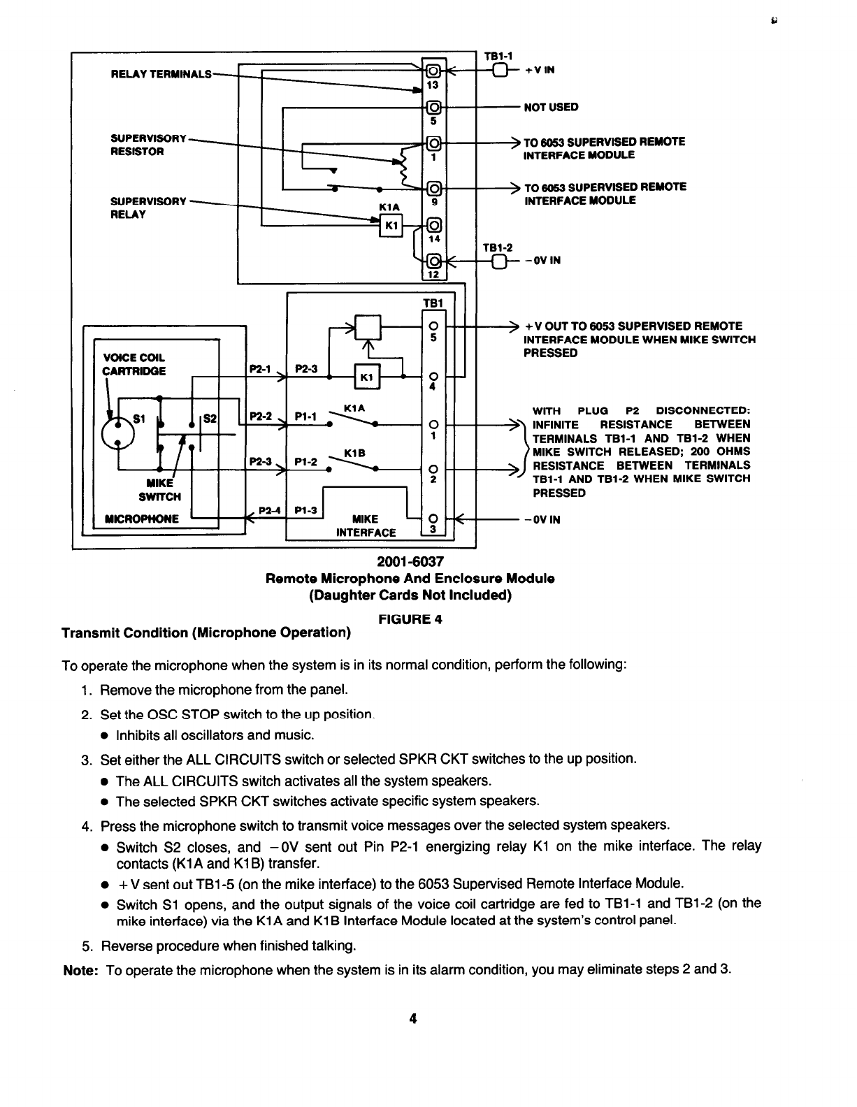
MODULE FUNCTION (Refer to Fig. 2)
Normal Condition
The microphone switch is in the released (off) position, and any output signals from the voice coil cartridge are
shunted through the switch Sl contacts.
P2-1
VOICE COIL ) -0V OUT WHEN MIKE SWITCH PRESSED
CARTRIDGE (OSC STOP)
P2-2 ’ WITH PLUG P2 DISCONNECTED: 0 OHMS
. s2 RESISTANCE BETWEEN PINS P2-2 AND
P2-3 WHEN MIKE SWITCH RELEASED;
l
200 OHMS RESISTANCE BETWEEN PINS
P2-3
.!
P2-2 AND P2-3 WHEN MIKE SWITCH PRESSED
MICROPHONE ’ P2-4 ) -0V IN (AUDIO SYSTEM COMMON)
2001-6030
Microphone And Enclosure Module
(Daughter Cards Not Included)
FIGURE 2
Transmit Condition (Microphone Operation)
To operate the microphone when the system is in its normal condition, perform the following:
1. Remove the microphone from the panel.
2. Set the OSC STOP switch to the up position.
l
Inhibits all oscillators and music.
3. Set either the ALL CIRCUITS switch or selected SPKR CKT switches to the up position.
l
The ALL CIRCUITS switch activates all the system speakers.
l
The selected SPKR CKT switches activates specific system speakers.
4. Press the microphone switch to transmit voice messages over the selected system speakers.
l
Switch Sl opens, and the output signals of the voice coil cartridge are fed to pins P2-2 and P2-3
(Common). The signals are then transmitted to the mike interface transformer.
l
Switch S2 closes, and - OV is sent out pin P2-1 (inhibits tape player, music and all oscillators).
5. Reverse procedure when finished talking.
Note:
To operate the microphone when the system is in its alarm condition, you may eliminate steps 2 and 3.
2