Simplified Building Easi-Dec Configuration guide

VERTICAL LADDER WITH CAGE INSTALL INSTRUCTIONS
Incorporating Lock Out Gate and Exclusion Zone Kits

LADDER SYSTEM ASSEMBLY INSTRUCTIONS
SECTION CONTENTS PAGE
1INTRODUCTION 1
1.1 Validity 1
1.2 Authorised Agent 1
1.3 Health and Safety 1
1.4 Familiarisation 1
1.5 Certifying Body 1
1.6 Anticipated Life 1
1.7 Safeguarding the Instruction For Use Manual 1
1.8 Copyright 1
1.9 Amendment Service 1
1.10 Modications to The Ladder System 1
1.11 Denition “Authorised Person” 1
1.12 Denition “Trained Person” 1
1.13 Use in Accordance with Regulations 1
1.14 Incorrect Use 2
1.15 Operators Duty of Care 2
1.16 Medical Condition of Users 2
1.17 Personnel Requirements 2
1.18 Rescue 2
1.19 Atmospheric Conditions 2
2 BASIC SAFETY INSTRUCTIONS 3
3 INSTALLATION 6
3.1 Tool List 6
3.2 Checking the Ladder system’s components 6
4 Installation Process for Lockout panel 9
5 Installation Process for Ladder with cage 11
6 PRE USE CHECKS 12
7 RECERTIFICATION 13

INTRODUCTION
1. INTRODUCTION
1.1 Validity
These operating instructions apply to the following product:
Type: Easi-Dec®Ladder System with Cage
Model Year: 2019
1.2 Authorised Agent
Easi-Dec Access Systems Ltd
7 Blaydon Road
Sandy
Bedfordshire, SG19 1RZ
Tel: +44 (0) 1767 691812
E-Mail: [email protected]
Internet: www.easi-dec.co.uk
1.3 Health and Safety
Installers and users must comply with all relevant health and safety regulations in their given territory.
1.4 Familiarisation
Before using Easi-Dec® Ladder System for the rst time it is recommended that the installers
attend a Kee Safety installation course.
1.5 Certifying Body
Kee Safet Test and Training Centre
1.6 Anticipated Life
Metal Components: Up to 25 years in non-marine, non-corrosive (e.g. chemical plant) environments
with a temperature range from –10 to + 55 degrees centigrade subject to use and a mandatory
annual inspection strictly in accordance with these instructions.
1.7 Safeguarding the Instruction Manual
This Instructions for Use document forms a component part of the Easi-Dec® Ladder System. It
must accompany the system and be followed for assembly. At no time must any pages be removed
from these instructions. If the instructions are lost in their entirety or in part, the instructions or the
missing parts must be replaced immediately.
1.8 Copyright
This documentation contains information protected by copyright. It may not be photocopied,
reproduced, translated or recorded on data media, either completely or as extracts, without prior
permission. We reserve all further rights.
1.9 Amendment Service
This document is not subject to any amendment service from the manufacturer. Amendments to
this documentation can’t be carried out without prior notice.
1.10 ModicationstoTheEasi-Dec® Ladder System
If you undertake modications to the Easi-Dec® Ladder System, you will negate all certication that
comes with this product and possibly cause death.
1.11 Denition“AuthorisedPerson”
A person is deemed to be an authorised person if they have fully read and understood the
instructions provided in this manual.
1.12 Denition“TrainedPerson”
Trained persons, are persons who, based on their specialist training and experience have adequate
knowledge of the system to be checked and are sufciently familiar with the relevant regulations,
guidelines and generally recognised rules of the Easi-Dec® Ladder System and accompanying
regulations - e.g., Health and Safety Regulations and Accident Prevention Regulations that are in
force in the country of use; and can assess the safe working conditions of the installation location. A
trained person shall be responsible for selecting all users of The Easi-Dec® Ladder System.
1.13 Use in Accordance with Regulations
The Easi-Dec® Ladder System provides an access vertically to roofs which are not accessible to the
public but to which access is required for the purpose of carrying out repairs and maintenance.
The Ladder system is designed as a permanently installed system. However, dismantling and
reconstruction at a different location is permissible under certain circumstances.
The Ladder system is only regarded as being used for its intended use if all the following conditions
are met:
The Ladder system is governed by various workplace Regulations and Guidelines. Operating
personnel must be familiar with the statutory requirements arising from these. They must also be
familiar with and adhere to the following specications and technical regulations:
HSG-33, Health & Safety in Roof work,
BS EN 14122 : 2006
The total weight of the Ladder system depends on the length and conguration of the
whole system. The load-bearing capacity of the structure the ladder is attached to must at
least correspond to the total weight of the system plus potential personnel. If in doubt, you
must arrange for the building structure to be examined by a structural engineer before assembly.
The Ladder system must be linked to the building’s lightning protection system if possible.
The Ladder system is only designed for use on those specied in the assembly
instructions. The maximum permissible load is.

INTRODUCTION
1.14 Incorrect Use
The following points are classed as misuse although the type of use appears possible at rst glance:
Use of the Easi-Dec® Ladder System if one of the conditions specied under “intended use“ is
not met.
Failure to observe the conditions relating to the xing surface specied under
“intended use“. If the conditions specied are not adhered to, then the Ladder system
may possibly fail.
Use of a damaged Ladder system or one which has been assembled incorrectly or is
incomplete.
Should the Ladder system be used in spite of these instructions, then the possibility of a
fall occurring and severe or fatal injury is possible.
UseofTheEasi-Dec® Ladder System in any of the above conditions is forbidden
1.15 Operator’s Duty of Care
The duties and obligations of the operator and trained personnel when dealing with The
Easi-Dec® Ladder System are set out below.
a) SafetyofTheEasi-Dec® Ladder System In particular, the owner or employer must ensure that the
Ladder system
is only used as intended,
is only provided in a fault-free, reliable state,
is checked regularly,
b) Instruction and Training
All users of the system must ensure that:
before using the system for the rst time and at least once annually thereafter, all personnel
shall be instructed in all relevant matters of health and safety at work (with particular
emphasis on Working at Height) and environmental protection.
the operating instructions are always available in a legible state, are complete and are kept
with the system at all times.
all users are familiar with the contents of these operating instructions.
The requirements the manufacturer places on the users of The Easi-Dec® Ladder System are as
follows:
c) Duties of the User
The user must full the following duties:
Assemble The Easi-Dec® Ladder System strictly in accordance with this Instructions for Use
Manual and check that the system is functioning correctly and safely.
Recognise any defects and withdraw the system from use and alert the manufacturer so an
assessment and required repairs can be completed.
d) Requirements of the User
In order to be able to full his or her duties, the user must meet the following requirements:
They must have adequate knowledge of the language in use in the country where the
system will be installed
They must be free from any disability that may affect their ability to use this system or
understand these instructions.
It is unlikely that any medical condition may directly affect (or be affected by) the use of this
product in itself, but users must be aware that:
Working at height is a dangerous occupation. They should be trained to do so, and
should comply with any medical requirements set by the training provider.
1.16 Atmospheric Conditions
CARE TO BE EXERCISED!
This Ladder system should never be used during periods when there is frost, ice or snow on the
ladder, or if these conditions are imminent.

INTRODUCTION
2. BASIC SAFETY INSTRUCTIONS
Basic safety instructions for the safe handling of the Easi-Dec® Ladder System can be found here.
DANGER TO LIFE!
It is imperative that you follow these safety instructions to avoid endangering your
life and safety.
Possible Danger Prevention Measures
DANGER TO LIFE!
There is a risk of the construction personnel falling
during assembly or when carrying out repairs.
Explanation:
Inadequate or insufcient safety measures or errors
during the assembly of the Ladder system can lead to
falls resulting in severe/fatal injuries.
• The Ladder system is only to be assembled as
specied in the assembly instructions.
• After assembly or after carrying out repairs,
check all structural parts and connecting
components to make sure that they are located
correctly.
• Do not use any parts that are damaged.
DANGER TO LIFE!
There is a risk of the Ladder system failing if the
installation site is unsatisfactory
Explanation:
A non-approved roof surface can result in The
Ladder system moving and failing.
• Follow the detailed information provided in this
document. If in doubt please contact us.
• The wall xing surface must always be of the
prescribed quality and load-bearing capacity.
• The prescribed measures must always be
complied with.
DANGER TO LIFE!
There is a risk of people falling due to failure to carry
out maintenance work on the Ladder System.
Explanation:
Defects or damage can impair the function of the
Walkway system therefore the system may possibly
not be guaranteed in the event of an emergency.
• If you have to access the roof via the Ladder
always carry out a visual check on the
Ladder system and the roof area beforehand for
damage.
• Any parts that are found to be damaged. must
always be replaced before any work is started. Only
then is it permitted to start the actual work on the
roof.
DANGER TO LIFE!
There is a risk of people falling due to attaching
Personal Protection Equipment to a Ladder system
Explanation:
The Ladder system must never be used to attach
P.P.E. to as an anchor for abseiling or similar work.
• The Ladder system is a stand alone Ladder sys-
tem and should always be treated as such. Under
no circumstances should the system be used as a
“man anchor” or as a connection for P.P.E.

INTRODUCTION
3. INSTALLATION
During installation at least two people should be working at all times. Prior to the Ladder system being
erected, any personnel on the roof should ensure they stay at least 2m from the edge of the roof at
all times.
Installers should wear and use:
EN 354 (Lanyards)
EN 355 (Energy absorbers)
EN 360 (Retractable type fall arresters) (> prEN 360:2016)
EN 361 (Full body harnesses)
EN 353-2 (Guided type fall arresters including a exible anchor line)
EN 358 (Belts for work positioning and restraint and work positioning lanyards)
A full body harness to EN361 is the only acceptable form of body holding device for fall
arrest systems.
The full body safety harness and lanyard should be suitably attached to a safe anchor point at all
times.
Installers and users must comply with all relevant health and safety regulations.
3.1 Tool List
Socket 17mm
Torque wrench 10- 60 Nm approx.
Drill with drill bit suitable for wall xings
Tape measure / Marker Pen
Level / Magnetic Plum Line
17mm Spanner
3.2 Checking the Ladder system’s components
If some of the parts listed in the parts list or on the delivery note are missing or damaged, then you
must replace them with original parts. Contact the manufacturer to obtain these.
Note: A complete list of all parts and details on the total weight of the Easi-Dec® Ladder System are
provided with the delivery. The load-bearing capacity of the structure must be equal to or exceed the
capacity specied.

LADDER SYSTEM ASSEMBLY INSTRUCTIONS
A. Attach upright posts with brackets to top of ladder using M10 x
40mm screws, at washers and nyloc nuts. Torque set to 18N/m.
B. Install GRP step at top of ladder, securing using M10 x 40
screws, at washer and nyloc nuts. Torque set to 18 N/m.
C. Attach large hoops to top and lower of upright posts as sown
above using M10 x 80mm screws, at washers and nyloc nuts.
Torque set to 18 N/m
D. Attach aluminium upright tube between to two large hoops
using M10 x 50mm screws, at washers and nyloc nuts. Torque
set to 18 N/m.
E. Connect upright return post between to two uprights using
A10-7, 15-7 and short length of tubes. To secure A10-7, push pin
through tting. Torque set to 39 N/m.
F. Attach hoops to upright stile on ladder posts threading M10 x
40mm screws through predrilled holes, securing with at washers
and nyloc nuts. Torque set to 18 N/m.

LADDER SYSTEM ASSEMBLY INSTRUCTIONS
G. Attach vertical strengthening at bars between to each hoop
using M10 x 40mm screws, at washers and nyloc nuts. Torque
set to 18 N/m.
H. Line ladder up with wall in required location and mark holes
to be drilled (the distance between brackets should be 800mm).
Mark point on ladder and drill and attached xing brackets. Drill
wall ready for insertion of suitable xings.
I. Secure ladder to wall and torque set wall xings as per
manufacturers instructions. Check all torque settings on ladder
components.
K. To ensure ladder is fully compliant with BS EN 4211 2016, a
KEE GATE or similar compliant gate must be attached at the top
of the ladder.
J. The assembled ladder shsould look like the above with no
parts missing.
L. Before use check to ensure ladder is thoroughly secured to
each xings and that all xings are corectly torqued. Failure to do
so could result in Death or serious injury.
!

LADDER LOCKOUT PANEL ASSEMBLY & INSTALLATION
9
Installation on the Exclusion Zone
The lock out panel product helps prevent use of ladders by unauthrosied persons.
PLEASE NOTE - A padlock with a 80mm shackle with a diameter not larger than 6mm is required to
lock the panel to the ladder.
TOOLS REQUIRED
No special tools are required.
Step 1
The ladder should be mounted to the wall as per instructions.
Step 2
Check all components are undamaged and are present.
Step 3
Follow steps on page 11 to ensure proper and safe connection.

LADDER LOCKOUT SYSTEM ASSEMBLY INSTRUCTIONS
A. The kit contains lockout plate and securing clamp. A suitable
80mm long, 6mm diameter shackle padlock is required (not
included).
B. At a suitable height, line the integrated hook of the lock out
panel up with rung of ladder and hook ladder over rung.
C. Once panel is hooked over the ladder and held in position, add
the C clamp by clamping around the rung and threading through
the pre-cut slots on the lockout panel.
D. Pass suitable padlock through C clamp and lock as shown in
diagram above.
E. Your lockout panel should look like the above. To remove the
panel, reverse the above process.

LADDER EXCLUSION ZONE PLANNING ASSEMBLY & INSTALLATION
11
Installation on the Exclusion Zone
The Exclusion Zone product creates an area directly below the ladder that should only be entered if no-one is
using the ladder. The kit consists of two guardrail frames and a powdercoated KEE GATE.
PLEASE NOTE - Suitable wall and oor xings are required to secure the gurardrail to a wall and ground surfaces.
Only trained engineers should install this product
TOOLS REQUIRED
You will need the following in order to install the
Exlcusion Zone kit
• Marker Pen
• Tape Measure
• 1No 17mm socket
• 3/8” Hex Key socket
• Torque Wrench 10- 60 Nm approx
• Hacksaw or Similar
• Drill with suitable drill bit
• Small Spirit Level
Step 1
Check all components in the kit. There should be 4no. horizontals, 2no. uprights, 4no. 61-8 ttings, 2no.
15-8 ttings and 2no. 10-8 ttings. The KEE GATE is packaged seperately.
Step 2
The width of the frame can be adjusted to suit individual site requirements. Standard width should be
1120mm centres. This should allow the gate to be tted without the need for cutting.
Step 3
Carefully follow the assembly instructions on next page.

LADDER EXCLUSION ZONE ASSEMBLY INSTRUCTIONS
A. Attach 10-8, 62-8 and 15-8 KeeKlamp ttings to upright
tube. The clearance distance between the top and mid rail
should not exceed 500mm.
B. Connect 61-8 ttings to the horzintal tubes and connect
upright from previous step as shown in diagram above. Torque all
ttings to 39N/m.
C. Attach 61-8 tting to ground and wall surfaces using suitable
xings. Following xing manufacturers guidance for correct
installation.
D- Connect KEE GATE to upright following the installation
instructions as provided with the KEE GATE product.

LADDERSYSTEMPRE-USECHECKS
Always carry out a risk assessment and method statement
Before each use, check ladder thoroughly for corrosion, signs of vandalism, and damage.
Always ensure that the area below where you are working is clearly marked to warn people of works above.
Follow HSE guidelines when working at height.
At the top of the ladder edge protection must be provided to comply with current work at height regulations and hierarchy of controls
The maximum load capacity for the ladder is 150kg

LADDER SYSTEM RECERTIFICATION
Periodic inspections by a competent person are required under the Temporary Work Equipment Directive 2009/104/EC – use of work equipment and Section 12 of the Work at Height Regulations.
The frequency will depend upon environment, location and usage, but should be at least every 12 months or before and after each use whichever soonest. Visually inspect the complete system
before installation ensuring all component parts are present.
Ensure the system has not been modied/tampered with by unauthorized persons.
DETAILED COMPONENT INSPECTION:-
Ladder
Check the complete Ladder for distortion, cracks or dents
Check the ladder for missing xings and stiles.
Check for any general corrosion.
Check for any signs of tampering or vadalism.
Ladder Cage
Check for any general corrosion.
Check the complete Ladder cage for distortion, cracks or dents
Check xings such as screws and nyloc nuts are all present
General
Once all other inspection points are completed, check that the whole device is xed securely in position with no obvious distortions in balance.
Always keep a log of all inspections and comments.


Simplified Building
Unit A2, Cradley Business
Park
Cradley Heath, Birmingham
B64 7DW
Tel: 01384 476 107
info@simplifiedsafety.co.uk
LCK_V1_23.8.19
Table of contents
Popular Ladder manuals by other brands

DROMAD HIRE
DROMAD HIRE 500Tower instruction manual

GÜNZBURGER STEIGTECHNIK
GÜNZBURGER STEIGTECHNIK 41306 Assembly and operating instruction
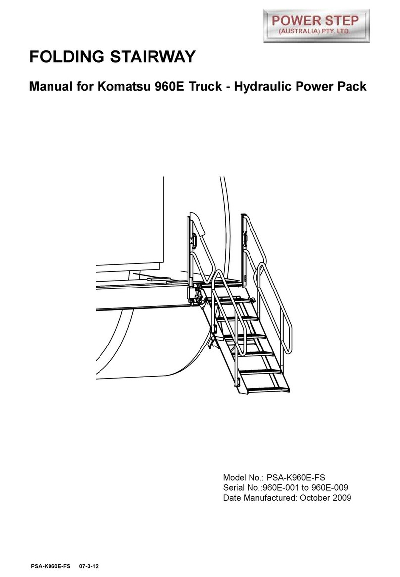
Power Step
Power Step Komatsu 960E manual

Stockmaster
Stockmaster Mezzalad VH01 User instructions
Vestil
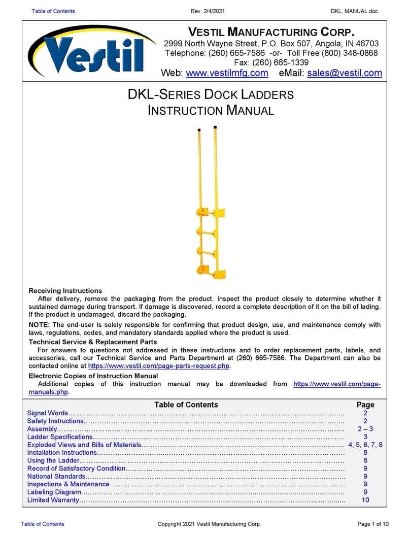
Vestil DKL Series instruction manual

Louisville
Louisville PK-E05R Assembly instructions


