SimpliPhi Power PHI 3.8 Quick setup guide

Power. On Your Terms.
SimpliPhi Power PHI Battery
Optimized Energy Storage & Management for Residential & Commercial Applications Utilizing
Efficient, Safe, Non-Toxic, Energy Dense Lithium Ferrous Phosphate (LFP) Chemistry
© SIMPLIPHI POWER, INC. REV070219
INTEGRATION GUIDE: VICTRON

SimpliPhi Power, Inc. | 3100 Camino Del Sol | Oxnard, CA 93030, USA | (805) 640-6700 | info@simpliphipower.com | SimpliPhiPower.com
| 2 |
SimpliPhi Your
Energy Security and
Independence
and gain control of your own power.
SimpliPhi helps you manage your power as a personal resource.
Anytime. Anywhere. SimpliPhi energy storage optimizes
integration of any power generation source –solar, wind,
generator –on or off grid and protects your home and mission-
critical business functions from power outages and intermittency.
SimpliPhi storage technology eliminates operating temperature
constraints, toxic coolants and the risk of thermal runaway and
fire. Safe lithium ferrous phosphate. No cobalt. No hazards.
SimpliPhi’s battery technology utilizes the industry’s most
environmentally benign chemistry combined with proprietary
architecture and power electronics (BMS) that eliminate the
need for cooling or ventilation to create products that provide
energy security and resiliency –all with a 98% efficiency rate.
SimpliPhi Power offers proprietary, commercially availableenergy
storage and management systems that are safe, non-toxic, reliable,
durable, efficient, highly scalable, and economical over the lifetime of the
PHI Battery.

REV070219
SimpliPhi Power, Inc. | 3100 Camino Del Sol | Oxnard, CA 93023, USA | (805) 640-6700 | info@simpliphipower.com | SimpliPhiPower.com
| 3 |
Table of Contents
1.0 –Introduction ........................................................................................................................................4
2.0 –Battery Bank Sizing ...........................................................................................................................4
2.1 –Discharge Calculation: Inverter Power Bank Sizing.........................................................................4
2.2 –Charge Calculation: Charge Controller Power Sizing......................................................................5
3.0 –Victron BMV-700 Installation & Setup..............................................................................................5
3.1 –Standard Features ...........................................................................................................................6
3.2 –Installation –Connections................................................................................................................6
3.3 –Installation –Quick Start Guide .......................................................................................................7
3.4 –Victron –Available Interfaces...........................................................................................................8
4.0 –Program Settings for PHI Batteries..................................................................................................8
4.1 –Depth of Discharge ..........................................................................................................................8
4.2 –PHI 3.8 General Settings with Victron..............................................................................................9
4.3 –Victron BMV-700 Programming Settings .........................................................................................9
4.4 –Inverter / Charger Settings.............................................................................................................10
4.5 –MPPT Settings ...............................................................................................................................11
4.6 –ESS Settings..................................................................................................................................12
5.0 –Specifications & Warranty ..............................................................................................................13
6.0 –SimpliPhi Technical Support ..........................................................................................................13

REV070219
SimpliPhi Power, Inc. | 3100 Camino Del Sol | Oxnard, CA 93023, USA | (805) 640-6700 | info@simpliphipower.com | SimpliPhiPower.com
| 4 |
1.0 –Introduction
This integration guide covers the recommended set up and configuration of Victron equipment for
optimizing performance with SimpliPhi PHI 3.8 kWh Batteries. More information on SimpliPhi products
can be found on our website: https://simpliphipower.com/.
If the Victron product you are looking for is not covered in this integration guide, the parameters listed
here should be used as a general guide.
The specific Victron product(s) installation and setup covered in this Integration Guide include:
•Victron BMV-7xx Series Battery Monitor
Programming parameters described herein relate to PHI 3.8 Battery general settings requirements as well
as to the following Victron Products:
•Victron Inverter / Chargers
oPhoenix VE.Direct Inverter
oMultiPlus and Quatro Inverter / Charger
•MPPT Solar Charge Controllers
•ESS
oGeneral
oColor Control or Venus GX
Based on tests and evaluations, the following parameters (refer to tables below) have been established.
More information on Victron products can be found on their website: https://www.victronenergy.com/.
More information on the Victron BMV-700 can be found on their website:
https://www.victronenergy.com/battery-monitors/bmv-700.
2.0 –Battery Bank Sizing
A properly sized PHI battery bank should be at least double (2x) the kW rating of the inverter(s) and have
a C/2 rating greater than the maximum charge controller rating. Depending on the specifications of the
equipment used in the system, sizing the PHI Battery bank based on these two criteria may yield different
results. Therefore, the best practice is to calculate the PHI Battery bank based on both criteria and use
the greater of the two results as the minimum quantity. We can compare these two calculation methods
assuming the nomenclature below:
•Battery rated continuous power = BatkWh (typically @ C/2)
•Inverter power full load = InvkW
•Maximum battery charge current = IBatChrgMax
•PV charge controller maximum = IPVChrgMax
•Recommended minimum number of batteries = B#
Discharge equation: B#Inv ≥ InvkW / BatkWh
Charge equation: B#PV ≥ IPVChrgMax / IBatChrgMax

REV070219
SimpliPhi Power, Inc. | 3100 Camino Del Sol | Oxnard, CA 93023, USA | (805) 640-6700 | info@simpliphipower.com | SimpliPhiPower.com
| 5 |
2.1 –Discharge Calculation: Inverter Power Bank Sizing
To optimize the PHI Battery bank and protect against over-discharge (voiding the battery Warranty), the
PHI Battery bank should be sized at least double (2x) the kW rating of the inverter.
Discharge Example: B#Inv ≥ InvkW / BatkWh
•Inverter is rated at 8 kW
•PHI Battery is rated at 3.8 kWh, therefore the C/2 load rating is 1.9 kW
B#Inv ≥8 kW / 1.9 kW = 4.21
A properly sized PHI Battery bank based on maximum discharge would have a minimum of 5 PHI
Batteries. This ensures no greater than C/2 battery load. If the PHI Battery bank has fewer batteries than
calculated, special care must be taken with the inverter settings to limit the load below the specified rating
of the PHI Battery. These settings are described in the following sections of this Integration Guide.
2.2 –Charge Calculation: Charge Controller Power Sizing
To optimize solar harvesting, a properly sized PHI Battery bank should be able to accept the maximum
PV charge current. To determine the minimum number of PHI Batteries required to optimize PV, divide
the output of the charge controller(s) by the “max continuous charge current” per PHI Battery. Be sure to
verify the “max continuous charge current” for the PHI Battery model that you’re using, because it may
differ from C/2 depending on the model.
Charge Example: B#PV ≥ IPVChrgMax / IBatChrgMax
•Maximum continuous charge current for PHI 3.8 kWh 48V = 37.5A
•PV charge controller max = 80A
B#PV ≥ 80A/37.5A = 2.13
A properly sized PHI Battery bank based on available PV charge would have a minimum of 3 PHI
Batteries. This maximizes the use of available PV while ensuring the PHI Batteries are never stressed by
overcharging. If the PHI Battery bank has fewer batteries than calculated, special care must be taken with
the inverter settings to limit the charge rate below the specified rating of the PHI Battery. These settings
are described in the following sections of this Integration Guide.
In summary: When comparing the same system using these two calculations for sizing the PHI
Battery bank, the minimum number of PHI Batteries should be the greater of the two results
(Discharge Calculation & Charge Calculation). In this example, this translates into 5 PHI Batteries
in the system.
3.0 –Victron BMV-700 Installation & Setup
The BMV-7xx series products will follow the general installation and settings in this section. The BMV-700
is used as a specific example here. Other products in this series have additional capabilities (i.e., the
BMV-702 has the capability to monitor an additional PHI Battery).
The BMV-700 is a precision battery monitor that functions as a ‘fuel gauge’ and indicates time remaining
in the PHI Battery bank. The remaining PHI Battery capacity depends on the ampere-hours consumed,
discharge current, temperature and the age of the PHI Battery. Ampere hours consumed are calculated
by integrating the current flowing in or out of the PHI Battery. Complex software algorithms are utilized to
take all these variables into account for an accurate reading. The monitor tracks several parameters
regarding the state of charge of the PHI Battery which can be used to evaluate usage patterns and
battery health.

REV070219
SimpliPhi Power, Inc. | 3100 Camino Del Sol | Oxnard, CA 93023, USA | (805) 640-6700 | info@simpliphipower.com | SimpliPhiPower.com
| 6 |
3.1 –Standard Features
The BMV-700 standard features include:
•Battery voltage, current, power, ampere-hours consumed and state of charge
•Remaining time at the current rate of discharge
•Programmable visual and audible alarm for alerts
•Programmable relay, to turn off non-critical loads or to run a generator when needed
•500 Amp quick connect shunt and connection kit
•Shunt selection capability up to 10.000 Amps
•VE Direct communication port - Stores a wide range of historical events, which can be used to
evaluate usage patterns and battery health
•Wide input voltage range: 9.5 –95V
•High current measurement resolution: 10 mA (0.01A)
•Low current consumption: 2.9Ah per month (4mA) @12V and 2.2Ah per month (3mA) @ 24V
•Bluetooth Smart dongle monitors your batteries on Apple or Android smartphones, tablets,
Macbooks and other devices
3.2 –Installation –Connections
Follow the instructions below to setup the BMV-700.
CAUTION: Connect the Negative Pole of the PHI Battery last!
1. Locate suitable place for 500A/50mV shunt and secure in place.
2. Remove fuse from PHI Battery supply cable.
3. Connect positive supply cable and appropriately sized PHI Battery positive cable to positive
output of PHI Battery bank and to the positive of the load/charger.
4. From the “load and charger” side of the shunt, connect appropriately sized negative cable to the
inverter or load/charger.
5. Connect positive supply cable to +B1 on the shunt.
6. Locate suitable place for the Victron meter and secure in place.
7. Connect UTP cable to rear of battery monitor.
8. Connect free end of UTP cable to battery shunt.
9. Connect appropriately sized negative cable between the “battery only” side of the shunt and the
negative output of the PHI Battery bank. Replace Fuse in fuse holder ensuring it is fully seated.
Please review Figure 1.0 below for additional detail.

REV070219
SimpliPhi Power, Inc. | 3100 Camino Del Sol | Oxnard, CA 93023, USA | (805) 640-6700 | info@simpliphipower.com | SimpliPhiPower.com
| 7 |
Figure 1.0 - BMV-700 Typical Installation
CAUTION: Connect the Negative Pole of the PHI Battery last!
3.3 –Installation –Quick Start Guide
After installation / connection, on initial startup, the BMV-700 “Setup Wizard” will automatically start. The
following steps should be used to initialize the meter.
1. BMV will automatically start the setup wizard.
a. The scrolling text “Battery Capacity “will appear.
i. Set the Ah capacity using the +/- buttons.
ii. Pressing “select” after each digit is selected.
iii. Calculate total bank capacity based on number of PHI Batteries in the bank.
iv. Example: 75Ah x 3 Batteries = 225Ah.
b. Press “setup” for 2 seconds to enter other parameters of the BMV.
c. Press “select” to access the desired parameter.
d. Use the +/- buttons to customize the settings.
e. For PHI 3.8 kWh Batteries, set parameters per Table 1.0 below.
f. Zero Current calibration: Disconnect the Negative cable between the load and shunt and
press “select”.
g. Synchronize: press “select”.
h. For any other settings, such as relay, temperature, or alarm settings, consult the BMV
Manual.
i. Press “setup” to end the wizard.
The BMV should be setup for normal use at this time.
If additional assistance is required, contact Victron Energy at: sales@victronenergy.com or call Victron at
+31 (0)36 5359700.

REV070219
SimpliPhi Power, Inc. | 3100 Camino Del Sol | Oxnard, CA 93023, USA | (805) 640-6700 | info@simpliphipower.com | SimpliPhiPower.com
| 8 |
CAUTION: If a firmware update is executed on Victron equipment, ALL the settings must be
reverified.
3.4 –Victron –Available Interfaces
The following interfaces are available from Victron to allow easy monitoring of the PHI Battery status /
performance.
•PC software BMV- Reader. Downloadable from Victron website in the support and downloads
section. Uses the VE.direct to USB interface.
•Color Control GX display featuring a 4.3-in color display can be connected to the BMV using
VE.direct to USB interface.
If additional assistance is required, contact Victron Energy at: sales@victronenergy.com or call Victron at
+31 (0)36 5359700.
4.0 –Program Settings for PHI Batteries
In order to maintain the Warranty, it is critical to ensure that the appropriate settings for the desired
Warranty are programmed in all the system components. This section will cover the basic concepts and
settings for the PHI 3.8 Batteries as well as settings specific to Victron products.
4.1 –Depth of Discharge
In order to optimize performance and the life of your system and PHI batteries, SimpliPhi Power
recommends programming the equipment settings for 80% Depth of Discharge (DoD). This qualifies for
the SimpliPhi 10-year / 10,000 cycle Warranty on the PHI Batteries. Greater DoD is possible, but will
result in reduced cycle life. Refer to the PHI 3.8 kWh Battery Warranty to compare DoD settings and the
associated Warranty.

REV070219
SimpliPhi Power, Inc. | 3100 Camino Del Sol | Oxnard, CA 93023, USA | (805) 640-6700 | info@simpliphipower.com | SimpliPhiPower.com
| 9 |
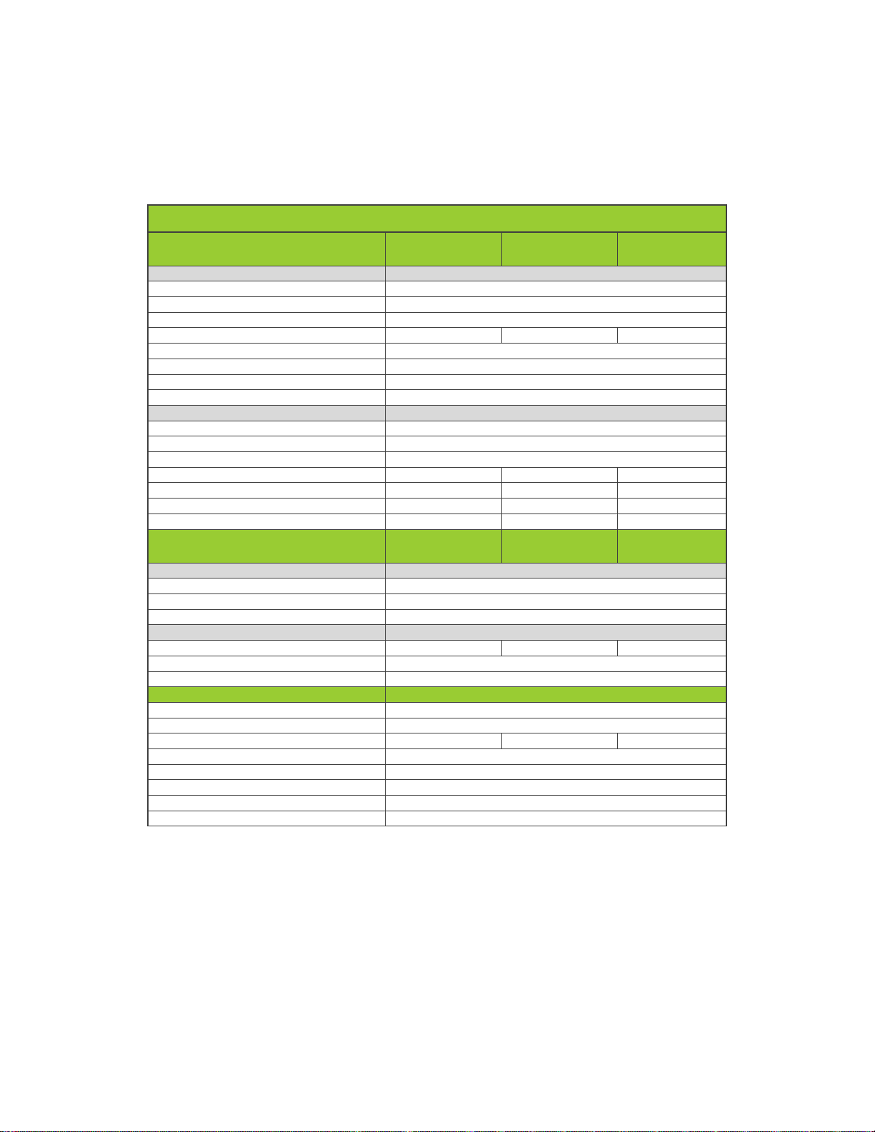
4.2 –PHI 3.8 General Settings with Victron
The general program settings for the PHI 3.8 Batteries with Victron products are outlined below.
Table 1.0 - Settings for SimpliPhi PHI 3.8 kWh 24V / 48V Battery w/Victron
General
10k Cycles
(80% DoD)
5k Cycles
(90% DoD)
3.5k Cycles
(100% DoD)
Battery Curve
Fixed
Capacity1(Ah)
151Ah per PHI3.8 24V; (302Ah for 2, 453Ah for 3)
75Ah per PHI3.8 48V; (150Ah for 2, 225Ah for 3)
Absorb Voltage (V)
27.2 / 54.4
27.2 / 54.4
28 / 56
Absorb Time
1 Hour
Float Voltage (V)
27 / 54 (typically Disable)
Discharge Voltage "LBCO" (V)
25.1 / 50.2
24.8 / 49.6
24 / 48
Re-Charge (V)
25.3 / 50.6
Max Discharge/Charge Current (C/2)1
45A per PHI3.8 24V; (90A for 2, 135A for 3)
37.5A per PHI3.8 48V; (75Afor 2, 112.5Afor 3)
Peukert Expo
1.05
Charge Efficiency
95%
SoC when Bulk Finished
95%
Notes:
•1. Per PHI 3.8 Battery –These settings are calculated by multiplying the nominal per battery value times the #
of batteries.
•Levels are typical @ 25°C and may need adjusting at temperature extremes.
•When performing rapid deep charge/discharge cycles, the PHI Battery should be allowed to "rest" 15 minutes
in between.
•Always refer to the SimpliPhi Power Manual and Warranty for the specific PHI Battery model.
4.3 –Victron BMV-700 Programming Settings
Table 2.0 - Settings for SimpliPhi PHI 3.8 kWh 48V Battery w/Victron BMV-700 Battery Monitor
Victron BMV-700 Settings
PHI 3.8 kWh 24V / 48V
Quick Start
Battery Capacity1(Ah)
151Ah per PHI3.8 24V; (302Ah for 2, 453Ah for 3)
75Ah per PHI3.8 48V; (150Ah for 2, 225Ah for 3)
Charged Voltage (V)
26.5 / 53.2
Tail Current (%)
4
Charge Detection Time (minutes)
1
Peukert Exponent
1.05
Charge Efficiency Factor (%)
98
Current Threshold (A)
0.1
Time to go Averaging Period (minutes)
3
Notes:
•1. Per PHI 3.8 Battery –These settings are calculated by multiplying the nominal per battery value times the #
of PHI Batteries.
•Levels are typical @ 25°C and may need adjusting at temperature extremes.
•When performing rapid deep charge/discharge cycles, the PHI Battery should be allowed to "rest" 15 minutes
in between.
•Always refer to the SimpliPhi Power Manual and Warranty for the specific PHI battery model.
CAUTION: When battery quantities change, the capacity current settings must to be reassessed.
REV070219
SimpliPhi Power, Inc. | 3100 Camino Del Sol | Oxnard, CA 93023, USA | (805) 640-6700 | info@simpliphipower.com | SimpliPhiPower.com
| 10 |
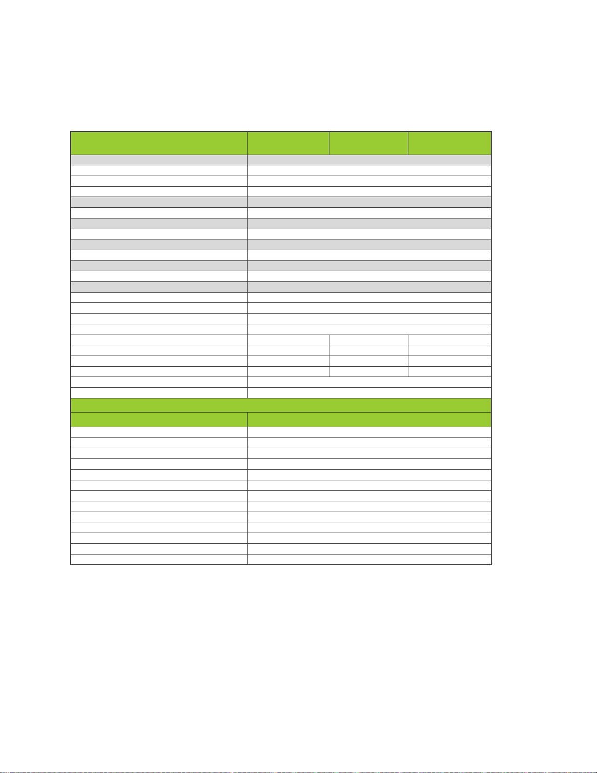
4.4 –Inverter / Charger Settings
The program settings for the PHI 3.8 Batteries with Victron Inverter / Charger products are outlined below.
Table 3.0 - Settings for SimpliPhi PHI 3.8 kWh 48V Battery w/Victron Inverter / Charger
Program Settings for SimpliPhi Model 3.8 - 48V with Victron Inverters / Chargers
Phoenix VE.Direct Inverters
10k Cycles
(80% DoD)
5k Cycles
(90% DoD)
3.5k Cycles
(100% DoD)
Victron Connect
Static Low Voltage Cutoff
Output Voltage
230V
Output Frequency
50Hz
Dynamic Cutoff
OFF
Low Battery Shutdown
50.2
49.6V
48V
Low Battery Restart & Alarm
54V
Charge Detect
54V
ECO Mode Wake-up Minimum Power
15W
ECO Mode Search Interval
2.5S
Victron Connect
Dynamic Low Voltage Cutoff
Enable Dynamic Cutoff
ON
Battery Type
Custom
Battery Capacity1
37.5A per PHI3.8; (75A for 2, 225A for 3)
Voltage for Discharge 0A
50.2
49.6V
48V
Voltage for Discharge 8A
50.2
49.6V
48V
Voltage for Discharge 23A
50.2
49.6V
48V
Voltage for Discharge 66A2
50
49.1V
47.5V
MultiPlus & Quattro
Inverter Chargers
10k Cycles
(80% DoD)
5k Cycles
(90% DoD)
3.5k Cycles
(100% DoD)
VE Configure
General Tab
SoC when Bulk Finished
95%
Total Battery Capacity1
75Ah per PHI3.8; (150Ah for 2, 225Ah for 3)
Charge Efficiency
95%
VE Configure
Inverter Tab
DC Input Low Shut-Down
50.2
49.6V
48V
DC Input Low Restart
50.5V
DC Input Low Pre-Alarm
51V
VE Configure
Charger Tab
Battery Type
Lithium
Lithium > Yes
Lithium Iron Phosphate
Absorb Voltage
54.4V
54.4V
56V
Float Voltage
54V
Charge Current (C/2)1
37.5A per PHI3.8; (75A for 2, 225A for 3)
Repeated Absorb Time
1 Hour
Repeated Absorb Interval
7 Days
Absorb Time
1 Hour
Notes:
•1. Per PHI 3.8 Battery –These settings are calculated by multiplying the nominal per battery value times the # of
batteries.
•2. These levels exceed the warrantied recommended operating conditions.
•Levels are typical @ 25°C and may need adjusting at temperature extremes.
•When performing rapid deep charge/discharge cycles, the PHI Battery should be allowed to "rest" 15 minutes in
between.
•Always refer to the SimpliPhi Power Manual and Warranty for the specific PHI Battery model.

REV070219
SimpliPhi Power, Inc. | 3100 Camino Del Sol | Oxnard, CA 93023, USA | (805) 640-6700 | info@simpliphipower.com | SimpliPhiPower.com
| 11 |
4.5 –MPPT Settings
The program settings for the PHI 3.8 Batteries with Victron MPPT products are outlined below.
Table 4.0 - Settings for SimpliPhi PHI 3.8 kWh 48V Battery w/Victron MPPT
MPPT Solar Charge Controllers
10k Cycles
(80% DoD)
5k Cycles
(90% DoD)
3.5k Cycles
(100% DoD)
Battery Voltage
48V
Max Charge Current (C/2)1
37.5A per PHI3.8; (75A for 2, 112.5A for 3)
Default Charge Settings
OFF
Absorb Voltage
54.4V
54.4V
56V
Absorb Time
1 Hour
Float Voltage
54V
Equalization Voltage
54V
Auto Equalization
OFF
Temperature Compensation
OFF
Notes:
•1. Per PHI 3.8 Battery –These settings are calculated by multiplying the nominal per battery value times the #
of batteries.
•Levels are typical @ 25°C and may need adjusting at temperature extremes.
•When performing rapid deep charge/discharge cycles, the PHI Battery should be allowed to "rest" 15 minutes
in between.
•Always refer to the SimpliPhi Power Manual and Warranty for the specific PHI Battery model.
REV070219
SimpliPhi Power, Inc. | 3100 Camino Del Sol | Oxnard, CA 93023, USA | (805) 640-6700 | info@simpliphipower.com | SimpliPhiPower.com
| 12 |
4.6 –ESS Settings
The program settings for the PHI 3.8 Batteries with Victron ESS products are outlined below.
Table 5.0 - Settings for SimpliPhi PHI 3.8 kWh 48V Battery w/Victron ESS
General
10k Cycles
(80% DoD)
5k Cycles
(90% DoD)
3.5k Cycles
(100% DoD)
VE Configure
General
SoC when Bulk Finished
95%
Total Battery Capacity1
75Ah per PHI3.8; (150Ah for 2, 225Ah for 3)
Charge Efficiency
95%
VE Configure
Grid Tab
N/A
No battery specific settings
VE Configure
Inverter Tab
N/A
Settings have NO EFFECT once ESS assistant is loaded
VE Configure
Charger Tab
N/A
Settings have NO EFFECT once ESS assistant is loaded
VE Configure
Virtual Switch Tab
N/A
Do NOT use VS
VE Configure
Assistants Tab
Battery System
System uses LiFePo4 with other type BMS
VE Configure Battery Type Selection
Change battery type as suggested
Sustain Voltage
50.2V
Dynamic Cut-Off
Discharge Rate Dependent
0.005C
50.2
49.6V
48V
0.25C
50.2
49.6V
48V
0.7C2
50.1
49.5V
48V
2C2
49.7
49.1V
48V
Restart Offset
1.2V
Victron Default Absorption Voltage
54.4V
FOR BACKUP ONLY SYSTEM
Color Control GX/Venus GX Settings
Keep Batteries Charged
Mode
Optimized (with BatteryLife)
Control Without Grid Meter
OFF
Inverter AC Output in use
ON
Feed-in Excess Solar charger Power
ON
Phase Compensation
ON
Minimum Discharge SoC3
90%
Actual State of Charge Limit
95%
BatteryLife State
Self-consumption
Limit Charger Power
OFF
Limit Inverter Power
OFF
Fronius Zero feed-in
OFF
Fronius Zero feed-in active
No battery specific settings
Grid setpoint
50W
Notes:
•1. Per PHI 3.8 Battery –These settings are calculated by multiplying the nominal per battery value times the # of PHI
Batteries.
•2. These levels exceed the warrantied recommended operating conditions.
•3. For BACKUP ONLY applications, set to desired backup level. This is the level batteries cycle to normally before
recharge. If the grid fails, cut-off is determined by the Dynamic Cut-Off values.
•Levels are typical @ 25°C and may need adjusting at temperature extremes.
•When performing rapid deep charge/discharge cycles, the PHI Battery should be allowed to "rest" 15 minutes in between.
•Always refer to the SimpliPhi Power Manual and Warranty for the specific PHI Battery model.

REV070219
SimpliPhi Power, Inc. | 3100 Camino Del Sol | Oxnard, CA 93023, USA | (805) 640-6700 | info@simpliphipower.com | SimpliPhiPower.com
| 13 |
5.0 –Specifications & Warranty
For your reference:
•See PHI 3.8 kWh 48V Specifications sheet.
•See PHI 3.8 kWh 48V 10-Year Warranty. Failure to adhere to installation protocol will void
Warranty.
6.0 –SimpliPhi Technical Support
For technical support related to your PHI 3.8 kWh Battery (or other SimpliPhi Power products), please
contact us directly at:
805.640.6700
techsupport@simpliphipower.com
Table of contents
Other SimpliPhi Power Camera Accessories manuals


