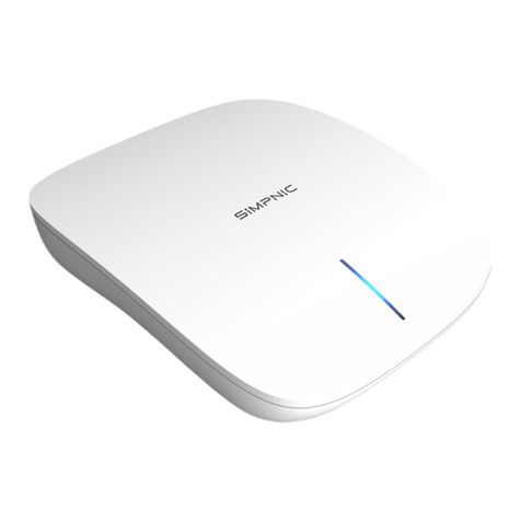
Simpnic S1 User manual

S1
IoT Gateway
User’s Guide
Version: 1.0

ii
Revision History
Version
Date
Changes
1.0
10/26/2018
First release
FCC Warning
This device complies with Part 15 of the FCC Rules. Operation is subject to the following two
conditions: (1) this device may not cause harmful interference, and (2) this device must accept any
interference received, including interference that may cause undesired operation.
Any changes or modifications not expressly approved by the party responsible for compliance
could void the authority to operate equipment.
This device and its antenna must not be co-located or operating in conjunction with any other
antenna or transmitter
For product available in the USA/Canada market, only channel 1~11 can be operated. Selection
of other channels is not possible
This equipment complies with FCC radiation exposure limits set forth for an uncontrolled
environment. This equipment should be installed and operated with minimum distance 20cm
between the radiator & your body.
This equipment has been tested and found to comply with the limits for a Class B digital device,
pursuant to part 15 of the FCC Rules. These limits are designed to provide reasonable protection
against harmful interference in a residential installation. This equipment generates, uses and can
radiate radio frequency energy and, if not installed and used in accordance with the instructions, may
cause harmful interference to radio communications. However, there is no guarantee that interference
will not occur in a particular installation. If this equipment does cause harmful interference to radio or
television reception, which can be determined by turning the equipment off and on, the user is
encouraged to try to correct the interference by one or more of the following measures:
—Reorient or relocate the receiving antenna.
—Increase the separation between the equipment and receiver.
—Connect the equipment into an outlet on a circuit different from that to which the receiver
is connected.
—Consult the dealer or an experienced radio/TV technician for help.
CE Mark Warning
This is a Class A product. In a domestic environment, this product may cause radio interference in
which case the user may be required to take adequate measures.
Trademarks
SiMPNiC is a registered trademark of Connection Technology Systems Inc.
All trademarks belong to their respective proprietors.
Contents subject to change without prior notice.
Copyright Statement
Connection Technology Systems Inc Copyright © 1998-2018
This publication may not be reproduced as a whole or in part, in any way whatsoever unless prior
consent has been obtained from Connection Technology Systems Inc.

iii
Contact Information
▓Headquarter/Manufacturer:
Connection Technology Systems Inc.
18F-6, No.79, Sec.1, Xintai 5th Rd.,
XiZhi Dist., New Taipei City 221, Taiwan(R.O.C)
Tel: +886-2-2698-9661
Fax: +886-2-2698-9662
Dir.Line:+886-2-2698-9201
www.ctsystem.com
www.simpnic.com
▓Global Authorized Representatives:
Connection Technology USA Inc.
40538 La Purissima Way, Fremont, CA 94539, USA
Tel: +1-510-509-0304
Sales Direct Line: +1-510-509-0305
E-mail:[email protected]
Connection Technology Systems Japan
Higobashi Bldg, No3 R201, 1-23-13, Edobori, Nisi-ku,
Osaka 550-0002, Japan
Tel: +81-6-6450-8890
E-mail: [email protected]
Connection Technology Systems NE AB
August Barks Gata 21,
421 32 Västra Frölunda, Sweden
Tel: +46-31-221980
E-mail: [email protected]
COMPONET Handels GmbH
Hirschstettner Straße 19-21/Stiege I
A-1220 Wien, Austria
Tel: +43-1-2350-5660
E-mail: [email protected]

iv
Table of Contents
Revision History .......................................................................................ii
CONTACT INFORMATION ...........................................................................III
TABLE OF CONTENTS ..............................................................................IV
CHAPTER 1. INTRODUCTION ...................................................................... 2
1.1 OVERVIEW OF S1................................................................................ 2
1.2 KEY FEATURES .................................................................................. 3
1.3 REAR &SIDE &TOP PANELS ................................................................... 5
1.3.1 Rear Panel ............................................................................... 5
1.3.2 Side and Top Panels ................................................................... 6
1.4 LED DEFINITIONS ............................................................................... 7
1.5 BUTTONS DESCRIPTION ......................................................................... 8
CHAPTER 2. INSTALLATION ....................................................................... 9
2.1 INSTALLATION REQUIREMENTS .................................................................10
2.2 CHECKING THE PACKAGE CONTENTS ..........................................................10
2.3 INSTALLING S1 GATEWAY ......................................................................11
2.3.1 Wall-Mounting Installation ............................................................11
2.4 CONNECTING S1 GATEWAY TO NETWORK .....................................................12
CHAPTER 3. OPERATION..........................................................................13
3.1 NETWORK MANAGEMENT .......................................................................13
CHAPTER 4. MAINTENANCE ......................................................................14
4.1 FAULT IDENTIFICATION .........................................................................14
4.1.1 Local Check ............................................................................14
4.2 HARDWARE REPLACEMENT PROCEDURES .....................................................15
4.3 FIRMWARE UPGRADE...........................................................................15

Publication date: Oct. 26, 2018
Revision 1.0 1
About this manual
In this user’s guide, it will not only clearly introduce SiMPNiC S1 Gateway but tell you how to install
this gateway with detailed instructions.
Organization of the Manual
Chapter 1 “Introduction” describes the features of the S1 Gateway
Chapter 2 “Installing the S1 Gateway”
Chapter 3 “Operation”
Chapter 4 “Maintenance”

Introduction
Publication date: Oct. 26, 2018
Revision 1.0
2
1
Introduction
SiMPNiC’s S1 Gateway is typically designed to meet the emerging Internet of Things (IoT) Ethernet
requirements. This reliable solution provides the security mechanism to prevent your network from
malicious attacks.
1.1 Overview of S1
With the cutting-edge technology, SiMPNiC delivers a managed Layer 2 gateway, S1, for IoT_based
services in the home automation. Through the Z-Wave transmission between the provided sensors
and this gateway, the users can remotely turn on/off the electrical appliances, monitor the status of
plugs/windows/doors, and so on anytime and anywhere using the SiMPNiC app we develop.
The LED indicator located on the top panel eases the users’ effort to monitor and manage the
network status. In addition, you can easily mount it with the wall-mount bracket we provide as well.

Introduction
Publication date: Oct. 26, 2018
Revision 1.0 3
1.2 Key Features
Z-Wave Plus S2 Security support.
Easy to use iOS& Android mobile App.
Support Wi-Fi and wired network connection.
Support WPS easy Wi-Fi connection.
2 x Buttons for easy Scene Control.
Lightweight, Stylish Design to blend into your house.
Simple installation with wall-mount kit.
SiMPNiC Edge Security (SES) & Firewall.
AES-128bit encryption both downstream and upstream.
Utilize Secure Tunnel to communicate with mobile App.
Anti-Tampering Firmware Design.
Emergency Boot to recover Firmware.
Patented Open Platform to Multi-Services.
Restful Open API for 3rd Party Development.
USB and SD card interface to FW upgrade and config restore.
Expandable Capability via USB Interface and SD card.
Interfaces:
-1 X USB 2.0(Type A) Port
-1 X RJ-45 Ethernet 10/100Mbps Port
-1 X Micro SD Slot
-IEEE ISM 802.11n 2T2R
Hardware:
-CPU: 1GHz
-RAM(Byte): 64MB
-FLASH(Byte): 16MB
LED:
-Status LED
Power:
-Power Source: AC-to-DC 5V micro USB Type B Adaptor
-Power Consumption: 1.3W (Min); 6.5W (Max.)

Introduction
Publication date: Oct. 26, 2018
Revision 1.0
4
Weight:
-0.22kg (Include the bracket)
Dimensions:
-120(W)x140(D)x37(H)mm
Temperature:
-Operating: 0ºC~40ºC;
-Storage: -20ºC~60ºC
Humidity:
-5%~90%, non-condensing

Introduction
Publication date: Oct. 26, 2018
Revision 1.0 5
1.3 Rear & Side & Top Panels
1.3.1 Rear Panel
The interfaces on the rear panel of S1 Gateway are described below:
A. Micro USB Power Jack
B. USB Connector
C. LAN Port
D. Micro SD Connector
Figure 1-1 Rear View of S1 Gateway
A
B
D
C
LAN Port
Micro USB
LAN Port
Micro USB
LAN Port
Micro USB

Introduction
Publication date: Oct. 26, 2018
Revision 1.0
6
1.3.2 Side and Top Panels
The interfaces on the side and top panels of S1 gateway are described below:
E. Pair Button (For more information, please refer to Section 1.5)
F. Action Buttons (For more information, please refer to Section 1.5)
G. Status LED (For more details on this LED description, please refer to Section 1.4)
H. Wall-mount Bracket (For more information, please refer to Section 2.3)
Figure 1-2. Side View of S1 Gateway
F
G
E
H

Introduction
Publication date: Oct. 26, 2018
Revision 1.0 7
1.4 LED Definitions
The S1 status is indicated by the Status LED on the top panel of the device.
LED
Color
Operation
Status
Yellow
Lit when the device is booting up.
Slowly blinking when the device is upgrading the
firmware or press the Pair button for 5 seconds and
then release to restart the system.
Rapidly blinking when pressing the Pair button for
more than 10 seconds and then release to reset
(return to factory default settings) and restart the
system.
Blue
Lit when the system boots up completely or the
device is in normal operation.
Red
Lit when the network connection fails.
Blinking when Z-Wave (include/ exclude fail) times
out or WPS fails. The LED indicator will blink in red
color for three times.
Blue Yellow
Blinking when pressing the Pair button twice and then
release to enter the Z-Wave “Included” mode.
Blue Red
Blinking when pressing the Pair button 3 times and
then release to enter the Z-Wave “Excluded” mode.
Red Yellow
Blue
Blinking when pressing the Pair button for 3 seconds
and then release to enable the WPS function.
Table 1-1

Introduction
Publication date: Oct. 26, 2018
Revision 1.0
8
1.5 Buttons Description
The following table contains various functions that will be proceeded when pressing Pair/Action
button of S1 Gateway.
Button
Description
Pair Button
Press the Pair Button of S1 for 3 seconds to enable the
WPS function.
Press the Pair Button of S1 for 5 seconds to reboot the
system.
Press the Pair Button of S1 for more than 10 seconds to
reset the system back to the factory default settings.
Press the Pair Button of S1 one time to abort the Z-Wave
connection.
Press the Pair Button of S1 twice to enter the Z-Wave
“Included” mode.
Press the Pair Button of S1 three times to enter the Z-Wave
“Excluded” mode.
Action Buttons
Press the “Left” Action Button of S1 one time to enter the
“Home” mode.
Press the “Right” Action Button of S1 one time to enter the
“Away” mode.
Press the “Left” Action Button of S1 twice to enter the mode
of Scene 1 you create.
Press the “Right” Action Button of S1 twice to enter the
mode of Scene 2 you create.
Table 1-2

Installation
Publication date: Oct. 26, 2018
Revision 1.0 9
2
Installation
To properly install S1 Gateway, please follow the procedures listed below. These procedures will be
respectively described in detail in the following sections.
Installation Requirements
Checking the Package Contents
Installing S1 Gateway
Powering on S1 Gateway
Connecting S1 Gateway to the Network

Installation
Publication date: Oct. 26, 2018
Revision 1.0
10
2.1 Installation Requirements
ATTENTION
Be sure to power off before installing or wiring your S1 Gateway.
2.2 Checking the Package Contents
Unpack the package carefully and check the package contents. The standard package should
contain the following items:
One set of S1 Gateway
1 x Power Adaptor and USB Power Cable
Wall-mount Bracket and Screws
1 x Network Cable (RJ-45)
This User’s Guide and Quick Installation Guide
Note: If any of the above items is found missing or damaged, please contact your local sales representative
for support or replacement.

Installation
Publication date: Oct. 26, 2018
Revision 1.0 11
2.3 Installing S1 Gateway
2.3.1 Wall-Mounting Installation
Just follow the procedures listed below for step-by-step instructions to mount S1 on the wall.
Select a proper space to drill 3 holes upon the mounting holes of the wall-
mount bracket shipped with the package.
Insert the screws supplied through the wall-mount bracket and into the holes
on the wall.
Tighten the screws with the screwdriver to secure mounting brackets to the
wall.
Lock downward carefully to secure S1. (See the arrow of Fig. 2-1 )
Arrange and hide cables under the bottom notch of the bracket if needed.
Fig. 3 S1
Gateway
Mounting
Figure 2-1. S1 Gateway
Mounting

Installation
Publication date: Oct. 26, 2018
Revision 1.0
12
2.4 Connecting S1 Gateway to Network
Connect to Network
Also follow the steps described below to complete the network installation for this gateway. You
may refer to Section 1.3 in this user’s manual for the correct locations of S1’s connectors. Before
powering on S1 Gateway, please make sure that network cables and power cables are securely
connected.
Connect the LAN Port of S1 to a router using the RJ-45 network cable. (Skip this step if
you decide using the wireless connection.)
Both enable the WPS function of S1 (Refer to Section 1-4 or Section 1-5) and a router
(Refer to router’s user manual). (Skip this step if you decide using the wired connection.)
Connect the WAN Port of your router to Internet using the RJ-45 network cable if you
would like to remotely connect to S1 via App.
Plug the power adaptor into the micro USB power jack of S1 and the status LED will light
up.
Download the SiMPNiC App from the iOS App Store/Android Google Play on your mobile
phones/tablets.

Operation
Publication date: Oct. 26, 2018
Revision 1.0 13
3
Operation
S1 Gateway provides flexible interfaces for users to configure, control and monitor the system
locally. To know the further information about the operation of this gateway, please refer to S1
Gateway Network Management User’s Manual for the detailed management functions and required
installation and operation procedures.
3.1 Network Management
Web Management is available in this gateway and can be done over the network. Once the
gateway is available on the network, you can login and monitor the status of it through a web
browser locally. Local Web management, especially for the first time use of the gateway to set up
the needed IP, can also be done through the 10/100Base-T 8-pin RJ-45 port located on the rear
panel of the gateway. Direct RJ-45 LAN cable connection between a router and the gateway is
required for this local management.
Note: The default IP Configuration Type of S1 is DHCP mode, a router with DHCP server function is
required in order to automatically provide IP address for S1.

Maintenance
Publication date: Oct. 26, 2018
Revision 1.0
14
4
Maintenance
This S1 Gateway is easy to maintain. The procedures are suggested when you would like to identify
faults, perform hardware replacement and do the firmware upgrade.
4.1 Fault Identification
Identifying faults can greatly reduce the time required to find problem and solution. Users may
perform local check or remote check to find the problems.
4.1.1 Local Check
Users can perform local check by observing LED indicators status or check system setup and
configuration through console connection.
When the whole system fails to function,
1. Check Status LED
2. Check Power connection
3. Reset power
When certain network link fails to function,
1. Locate the LAN port of the gateway
2. Check Status LED of the gateway
3. Check cable connection between the LAN port and the connected device
4. Reset power

Maintenance
Publication date: Oct. 26, 2018
Revision 1.0 15
4.2 Hardware Replacement Procedures
WARNING!
The S1 Gateway contains no user-serviceable parts. DO NOT, UNDER ANY
CIRCUMSTANCES, open and attempt to repair it.
Failure to observe this warning could result in personal injury or death from
electrical shock.
Failure to observe the above warning will immediately void any Warranty.
4.3 Firmware Upgrade
This S1 Gateway may perform the firmware upgrade when required. The latest firmware can be
downloaded using OTA (Over-the-Air) technology via your mobile phones/tablets to have your S1
Gateway updated automatically with the latest firmware. For more details on web upgrade
procedures, please refer to S1 Gateway Network Management User’s Manual.

Other manuals for S1
1
Table of contents
Other Simpnic Gateway manuals
