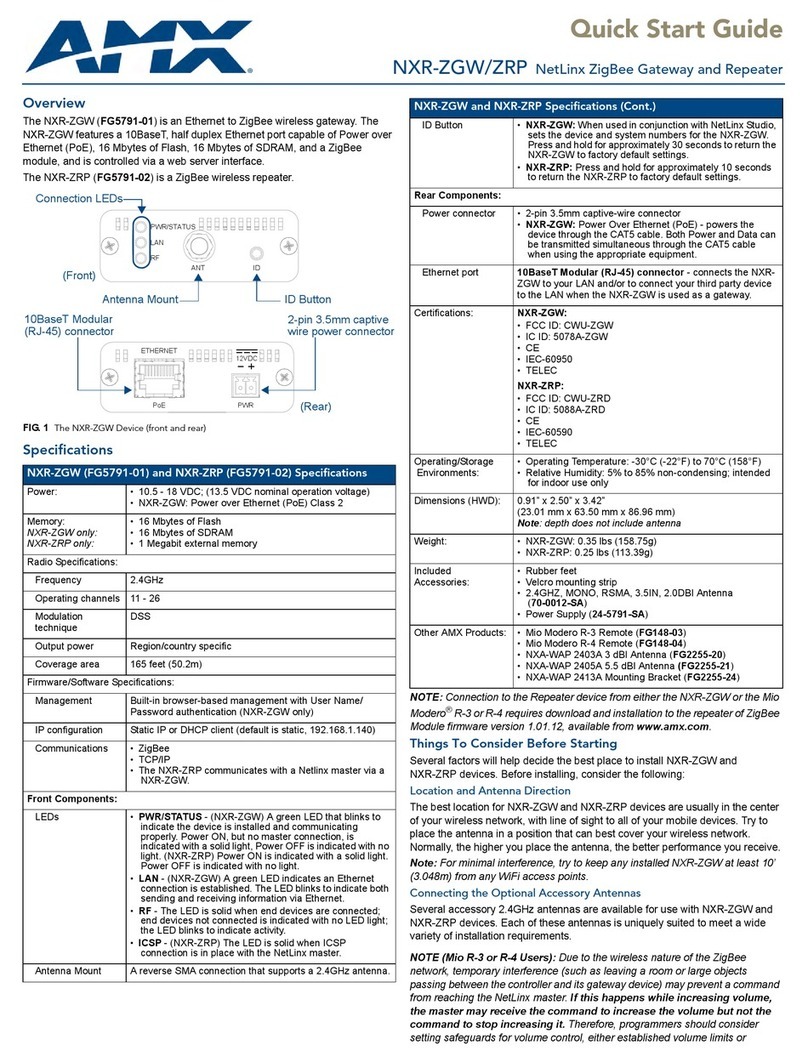
Simpnic S1 User manual

1
S1
IoT Gateway
Network Management
User’s Manual
Version 0.9

2
Revision History
Version
F/W
Date
Description
0.9
1.01.02
2018/09/07
First release

3
Trademarks
SiMPNiC is a registered trademark of Connection Technology Systems Inc..
Contents are subject to revision without prior notice.
All other trademarks remain the property of their owners.
Copyright Statement
Copyright Connection Technology Systems Inc..
This publication may not be reproduced as a whole or in part, in any way whatsoever unless prior consent has
been obtained from Connection Technology Systems Inc..
Changes or modifications to the equipment, which are not approved by the party responsible for compliance, could affect the
user’s authority to operate the equipment.
Copyright © 2018 All Rights Reserved.
Company has an on-going policy of upgrading its products and it may be possible that information in this document is not
up-to-date. Please check with your local distributors for the latest information. No part of this document can be copied or
reproduced in any form without written consent from the company.
Trademarks:
All trade names and trademarks are the properties of their respective companies.

4
CTS Contact Information
▓Headquarter/Manufacturer:
Connection Technology Systems Inc.
18F-6, No.79, Sec.1, Xintai 5th Rd.,
XiZhi Dist., New Taipei City 221, Taiwan(R.O.C)
Tel: +886-2-2698-9661
Fax: +886-2-2698-9662
Dir.Line:+886-2-2698-9201
www.ctsystem.com
www.simpnic.com
▓Global Authorized Representatives:
Connection Technology USA Inc.
40538 La Purissima Way, Fremont, CA94539, USA
Tel: +1-510-509-0304
Sales Direct Line: +1-510-509-0305
E-mail:[email protected]
Connection Technology Systems Japan
Higobashi Bldg, No3 R201, 1-23-13, Edobori, Nisi-
ku, Osaka 550-0002, Japan
Tel: +81-6-6450-8890
E-mail: cts_japan@ctsystem.com
Connection Technology Systems NE AB
August Barks Gata 21,
421 32 Västra Frölunda, Sweden
Tel: +46-31-221980
E-mail: [email protected]
COMPONET Handels GmbH
Hirschstettner Straße 19-21/Stiege I
A-1220 Wien, Austria
Tel: +43-1-2350-5660
E-mail: [email protected]

5
Table of Content
Chatper 1. OVERVIEW.........................................................................................................7
1.1 Management Preparations...........................................................................................7
1.1.1 Connecting the Gateway Controller.......................................................................7
1.1.2 Assigning IP Addresses .........................................................................................8
Chapter 2. WEB MANAGEMENT.........................................................................................9
2.1 System Information ....................................................................................................12
2.2 User Authentication ....................................................................................................13
2.3 Network Management ................................................................................................16
2.3.1 Network Configuration .........................................................................................17
2.3.2 System Service Configuration..............................................................................21
2.3.3 Wireless Configuration.........................................................................................22
2.3.4 Time Server Configuration...................................................................................26
2.4 Port Management.......................................................................................................28
2.4.1 Port Configuration................................................................................................29
2.4.2 Port Status...........................................................................................................30
2.5 RESTful......................................................................................................................31
2.5.1 RESTful Configuration.........................................................................................31
2.6 MQTT Control.............................................................................................................33
2.6.1 MQTT Configuration ............................................................................................34
2.6.2 MQTT HTTPAuth-Code Get Configuration .........................................................38
2.6.3 MQTTAuth-Code Get Configuration....................................................................39
2.7 Z-Wave.......................................................................................................................40
2.7.1 Z-Wave Network Manager...................................................................................41
2.7.1.1 Add and Remove the Sensors to/from an Existing Z-Wave Network ............43
2.7.1.2 Remove Failed Node from an Existing Z-Wave Network ..............................44
2.7.1.3 Replace Failed Node from an Existing Z-Wave Network...............................44
2.7.2 Z-Wave Node Controller......................................................................................45
2.7.2.1 Notification Settings.......................................................................................48
2.7.2.2 Power Level Settings.....................................................................................57
2.7.2.3 Association Settings......................................................................................58
2.7.2.4 Battery Status................................................................................................60
2.7.2.5 Door Lock Settings........................................................................................60
2.7.2.6 User Code Settings.......................................................................................62

6
2.7.2.7 Wake Up Settings..........................................................................................62
2.7.2.8 Sensor Multilevel Settings.............................................................................64
2.7.2.9 Basic Settings ...............................................................................................66
2.7.2.10 Binary Settings............................................................................................67
2.7.2.11 Switch Multilevel Settings............................................................................67
2.7.2.12 Meter Settings.............................................................................................69
2.7.2.13 Thermostat Setpoint Settings......................................................................70
2.7.2.14 Thermostat Mode Settings ..........................................................................71
2.7.2.15 Configuration Settings.................................................................................72
2.8 Z-Wave Utility.............................................................................................................74
2.8.1 Z-Wave HTTP Upgrade .......................................................................................74
2.8.2 Z-Wave Upgrade..................................................................................................75
2.8.3 Z-Wave Save Configuration.................................................................................76
2.9 Z-Wave IMA................................................................................................................77
2.9.1 IMA Last Working Route(LWR)............................................................................78
2.9.2 IMATransmission Diagnosis................................................................................79
2.10 System Utility............................................................................................................81
2.10.1 Ping ...................................................................................................................82
2.10.2 Event Log...........................................................................................................82
2.10.3 HTTP Upgrade...................................................................................................83
2.10.4 FTP/TFTP Upgrade ...........................................................................................84
2.10.5 Load Factory Settings........................................................................................85
2.10.6 Load Factory Settings Except Network Configuration........................................86
2.11 Save Configuration...................................................................................................87
2.12 Reset System...........................................................................................................87
2.13 Logout ......................................................................................................................88
APPENDIX A: DHCP Auto-Provisioning Setup................................................................89
APPENDIX B: Free RADIUS readme.................................................................................98
APPENDIX C: Z-Wave Terminology..................................................................................99
APPENDIX D: Control Command Class Table...............................................................100

7
1. OVERVIEW
This controller is a Z-Wave static controller.
This product can be included and operated in any Z-Wave network with other Z-Wave
certified devices from other manufacturers and/or other applications. All non-battery operated
nodes within the network will act as repeaters regardless of vendor to increase reliability of
the network.
This device is a security enabled Z-Wave Plus product that is able to use encrypted Z-Wave
Plus message to Enabled Z-Wave Plus devices.
Replication refers to the protocol replication between Controllers that is used to exchange
protocol data between different Controllers of the same network.
The controller ignores any Basic Command class if receiving Basic Set from a sensor.
The controller supports Association Command Class. It has one association group, which is
Lifeline group with grouping identifier equal to 1. Maximum number of devices that can be
added to the group is 1. When the device is reset, this group returns Device Reset Locally
notification.
The controller supports the listed browsers: IE, Firefox and Google Chrome.
1.1 Management Preparations
The gateway controller can be accessed through both Telnet connection and a web browser
such as Internet Explorer, Google Chrome or Firefox, etc…Before you can access the
gateway controller and configure it, you need to connect cables properly.
1.1.1 Connecting the Gateway Controller
It is extremely important that proper cables are used with correct pin arrangements when
connecting the Gateway Controller to other devices such as routers, switches, hubs,
workstations, etc..
10/100/Base-T RJ-45 Port
Depending on the model that you purchased, one 10/100Base-T RJ-45 port is located
on the rear panel of the Gateway controller. The RJ-45 port allows users to connect
their traditional copper-based Ethernet devices to network. This port supports auto-
negotiation and MDI/MDIX auto-crossover, i.e. the crossover or straight through CAT-5
cable may be used.

8
1.1.2 Assigning IP Addresses
IP addresses have the format n.n.n.n, for example 168.168.8.100.
IP addresses are made up of two parts:
The first part (168.168.XXX.XXX in the example) indicates network address identifying
the network where the device resides. Network addresses are assigned by three
allocation organizations. Depending on your location, each allocation organization
assigns a globally unique network number to each network that wishes to connect to
the Internet.
The second part (XXX.XXX.8.100 in the example) identifies the device within the
network. Assigning unique device numbers is your responsibility. If you are unsure of
the IP addresses allocated to you, consult the allocation organization from which your
IP addresses were obtained.
Remember that an address can be assigned to only one device on a network. If you connect
to the outside, you must change all the arbitrary IP addresses to comply with those you have
been allocated by the allocation organization. If you do not do this, your outside
communications will not be connected.
A subnet mask is a filtering system for IP addresses. It allows you to further subdivide your
network. You must use the proper subnet mask for a proper operation of a network with
subnets defined.

9
2. WEB MANAGEMENT
You can manage S1 gateway via a web browser locally. The default IP of this Gateway
Controller is set as DHCP mode. Through the connection of the RJ-45 port on the rear panel
of S1 using a RJ45 cable with a router, you will be allowed to have an access of S1 with the
IP address automatically obtained form this router for the first time. (You can change the IP
address of S1 to the desired one later in its Network Management menu.)
Initiate a web browser and input the IP address assigned by the connected router to enter S1
system. Once you gain the access, the following login window will appear. Also input the
default administrator username admin and last four letters of (MAC address + UID + serial
number) as the default password to login into the main screen page.

10
After you login successfully, the screen with the Main Menu will show up.
In the Main Menu, there are 10 main functions, including System Information, User
Authentication, Network Management, Port Management, RESTful Configuratin, MQTT
Control, Z-Wave Configuration, Z-Wave Utility, Z-Wave IMA, System Utility, Save
Configuration, Reset System and Logout contained. We will respectively describe their sub-
functions in the following sections of this chapter.
1. System Information: Name the Gateway Controller, specify the location and check the
current version of information.
2. User Authentication: View the registered user list. Add a new user or remove an existing
user.
3. Network Management: Set up or view the Gateway Controller’s IP address and related
information required for network management applications.
4. Port Management: Set up port configuration and view the port status.
5. RESTful Configuratin: Configure RESTful API for the communication between the
SiMPNiC app and gateway.
6. MQTT Control: Set up MQTT Configuration and view MQTT status.
7. Z-Wave: Manage Z-Wave network, add/delete Z-Wave sensors, and set up Z-Wave
sensor configuration.
8. Z-Wave Utility: For the configuration related to Z-Wave, including save/backup/restore
configuration files.
9. Z-Wave IMA: Analyze Z-Wave network traffic condition, and set up/delete the route.

11
10.System Utility: Ping, do the firmware upgrade, load the factory default settings, etc..
11.Save Configuration: Save all changes into the system.
12.Reset System: Reboot the Gateway Controller.
13.Logout: Exit the management interface.

12
2.1 System Information
Select System Information from the Main Menu and then the following screen shows up.
Company Name: Enter a company name up to 55 alphanumeric characters for this Gateway
Controller.
System Object ID: View-only field that shows the predefined System OID.
System Contact: Enter contact information up to 55 alphanumeric characters for this
Gateway Controller.
System Name: Enter a unique name up to 55 alphanumeric characters for this Gateway
Controller. Use a descriptive name to identify the Gateway Controller in relation to your
network, for example, “Backbone 1”. This name is mainly used for reference.
System Location: Enter a brief description of the Gateway Controller location up to 55
alphanumeric characters. The location is for reference only.
DHCP/DHCPv6 Vendor ID: Enter the user-defined vendor ID up to 55 alphanumeric
characters. Please make sure you have an exact DHCP Vendor ID with the value specified in
“vendor-classes” in your dhcp.conf file. For detailed information, see Appendix A.
Model Name: View-only field that shows the product’s model name.

13
Host Name: View-only field that shows the product’s host name.
Firmware Version: The firmware version of the first image.
1000M Port Number: The number of ports supporting 1000Mbps transmission speed.
100M Port Number:The number of ports supporting 100Mbps transmission speed.
M/B Version: View-only field that shows the main board version.
Serial Number: View-only field that shows the serial number of this Gateway Controller.
Date Code: View-only field that shows the Gateway Controller firmware date code.
Up time: View-only field that shows how long the device has been powered on.
Local Time: View-only field that shows the time of the location where the Gateway Controller
is.
Usb and SD card: View-only field that shows the installation status of USB connector and
Micro SD connector.
WiFi Regdomain: View-only field that shows the regulatory domain used to reconfigure
wireless drivers to make sure that wireless hardware usage complies with local laws set by
the FCC, ETSI and other organizations.
2.2 User Authentication
To prevent any unauthorized operations, only registered users are allowed to operate the
Gateway Controller. Users who would like to operate the Gateway Controller need to create a
user account first.
To view or change current registered users, select User Authentication from the Main Menu
and then the following screen page shows up.

14
Password Encryption: Pull down the menu of Password Encryption to disable or enable
MD5 (Message-Digest Algorithm). It is a widely used cryptographic hash function producing a
128-bit (16-byte) hash value, typically expressed in text format as a 32 digit hexadecimal
number. The default setting is disabled.
Click New to add a new user and then the following screen page appears. Up to 10 users can
be registered.
Click Edit to modify a registered user’s settings.
Click Delete to remove the selected registered user from the user list.
Current/Total/Max Users: View-only field.
Current: This shows the number of registered user currently.
Total: This shows the amount of total users who have already registered.
Max: This shows the maximum accounts are available for registration. The maximum
number is 10.
Account State: Enable or disable this user account.

15
User Name: Specify the authorized user login name. Up to 20 alphanumeric characters can
be accepted.
Password: Enter the desired user password. Up to 20 alphanumeric characters can be
accepted.
Retype Password: Enter the password again for double-checking.
Description: Enter a unique description for this user. Up to 35 alphanumeric characters can
be accepted. This is mainly used for reference only.
Console Level: Select the desired privilege level for the management operation from the
pull-down menu. Three operation levels of privilege are available in the Gateway Controller:
Administrator: Own the full-access right. The user can maintain user account as well
as system information, load the factory default settings, and so on.
Read & Write: Own the partial-access right. The user is unable to modify user account,
system information and items under System Utility menu.
Read Only: Allow to view only.
NOTE:
1. To prevent incautious operations, users cannot delete their own account, modify their
own user name and change their own account state.
2. The acquired hashed password from backup config file is not applicable for user login
on Web interface.
3. We strongly recommend not to alter off-line Auth Method setting in backup configure file.
4. If Auth-Method is enabled and do firmware downgrade, users must reset default config.

16
2.3 Network Management
In order to enable network management of the Gateway Controller, proper network
configuration is required. To do this, click the folder Network Management from the Main
Menu and then several options will be displayed for your selection.
1. Network Configuration: Set up the required IP configuration of the Gateway Controller.
2. System Service Configuration: Enable or disable the specified network services.
3. Wireless Configuration: Set up wireless configuration of the Gateway Controller.
4. Time Server Configuration: Set up the time server’s configuration.

17
2.3.1 Network Configuration
Click the option Network Configuration from the Network Management menu and then the
following screen page appears.
Enable IPv4: Click the checkbox in front of enable IPv4 to enable IPv4 function on the
Gateway Controller.
MAC Address: This view-only field shows the unique and permanent MAC address
assigned to the Gateway Controller. You cannot change the Gateway Controller’s
MAC address.
Configuration Type: There are two configuration types that users can select from the
pull-down menu, "DHCP" and "Manual". When "DHCP" is selected and a DHCP
server is also available on the network, the Gateway Controller will automatically get
the IP address from the DHCP server. If "Manual" is selected, users need to specify
the IP address, Subnet Mask and Gateway.
IP Address: Enter the unique IP address of this Gateway Controller. You can use the
default IP address or specify a new one when the situation of address duplication
occurs or the address does not match up with your network. (The default factory
setting is 192.168.0.1.)

18
Subnet Mask: Specify the subnet mask. The default subnet mask values for the three
Internet address classes are as follows:
Class A: 255.0.0.0
Class B: 255.255.0.0
Class C: 255.255.255.0
Gateway: Specify the IP address of a gateway or a router, which is responsible for the
delivery of the IP packets sent by the Gateway Controller. This address is required
when the Gateway Controller and the network management station are on different
networks or subnets. The default value of this parameter is 0.0.0.0, which means no
gateway exists and the network management station and Gateway Controller are on
the same network.
DNS Server 1 IP/IPv6 Address: Specify the IP/IPv6 address of the primary DNS
server.
DNS Server 2 IP/IPv6 Address: Specify the IP/IPv6 address of the secondary DNS
server.
Current State: This View-only field shows currently assigned IP address (by DHCP or
manual), Subnet Mask and Gateway of the Gateway Controller.
Enable IPv6: Click the checkbox in front of enable IPv6 to enable IPv6 function on the
Gateway Controller.
Auto-configuration: Enable Auto-configuration for the Gateway Controller to get IPv6
address automatically or disable it for manual configuration.
IPv6 Link-local Address/Prefix length: The Gateway Controller will form a link-local
address from its MAC address and the link-local prefix FE80::/10. This is done by
putting the prefix into the leftmost bits and the MAC address (in EUI-64 format) into the
rightmost bits, and if there are any bits left in between, those are set to zero.
IPv6 Global Address/Prefix length: This is done in the same fashion as the link-local
address, but instead of the link-local prefix FE80:: it will use the prefix supplied by the
router and put it together with its identifier (which by default is the MAC address in EUI-
64 format).
IPv6 Gateway: Specify the IP address of a gateway or a router, which is responsible
for the delivery of the IP packets sent by the Gateway Controller. This address is
required when the Gateway Controller and the network management station are on
different networks or subnets.

19
DHCPv6: Enable or disable DHCPv6 function
Disable: Disable DHCPv6.
Enable auto mode: Configure DHCPv6 function in auto mode.
Enable force mode: Configure DHCPv6 function in force mode.
Rapid Commit: Check to enable Rapid Commit which allows the server and client to
use a two-message exchange to configure clients, rather than the default four-
message exchange,
DHCPv6 unique identifier (DUID): View only field shows The DHCP Unique Identifier
(DUID).
Current State: This View-only field shows currently assigned IPv6 address (by auto-
configuration or manual) and Gateway of the Gateway Controller.
P2P Server: Enable or disable the P2P function.
Current State: Display the connection status bewteen the Gateway Controller and
P2P server.
P2P UID: The unique UID used to register to P2P server.

20
Source Binding state: Globally enable or disable IP source binding.
State: Disable or enable the assigned IP address to reach the management.
IP/IPv6 Address: Specify the IP address for source binding.
NOTE: This Gateway Controller also supports auto-provisioning function that enables
DHCP clients to automatically download the latest Firmware and configuration image from
the server. For information about how to set up a DHCP server, please refer to APPENDIX
A.
Other manuals for S1
1
Table of contents
Other Simpnic Gateway manuals
Popular Gateway manuals by other brands
Grandstream Networks
Grandstream Networks GXW-4024 user manual
MIMAKI
MIMAKI MDL Operation manual

Alcatel-Lucent
Alcatel-Lucent OmniAccess 5305 BG user guide
Dragino
Dragino LG01N user manual
Innoband
Innoband 8520-R1 user manual
Donaldson
Donaldson iCue Sensor Integrated Gateway Installation, operation and maintenance manual

