Simpro M25 Series User manual
Smart Lifting
OWNER’S MANUALM25 Series Pallet Truck
Smart Lifting
Owner’s Manual // M25 Series Pallet TruckOriginal Version // English // v1.0 // January 2021

Warning1.Read and understand the entire owners manual before using the pallet truck.2.Do not place hands or feet under the pallet truck at any time.3.Never allow anyone to ride on the pallet truck.4.Operate on smooth, level, nished oors only; do not use on ramps or sloping oors.5.To prevent accidental tipping, make sure load is centered on the fork.6.Do not lift a load with fork tips only. This may cause damage to the fork and personal injury if the rear of the pallet truck suddenly tips upward.7.Do not load pallet truck beyond its rated capacity.8.Never leave a loaded pallet truck unattended in the raised position. Always lower load to the oor.9.Pull pump release lever slowly to allow load to descend in a controlled manner.10.Secure load before transporting.11.Do not move a loaded pallet truck by other than manual force.12.The handle is designed to pull and steer the pallet truck only. Do not use the handle as a leverage tool.13.Failure to comply with these warnings may result in personal injury and/or property damage.M25 Series Pallet TruckModelM25M25LM25WM25SOperationPedestrianCapacity2500kg (dual-mode ‘quiklift’ hydraulic pump)Load center600mmService Weight~65kg~65kg~75kg~70kgFork Dimensions540x1150mm540x1150mm685x1220mm540x1150mmLowered Fork Height85mm65mm85mm85mmLifting Height165mmTurning Angle210°Turning Radius~1286mmMaterialsMild steel with powdercoat finish304 stainless steel
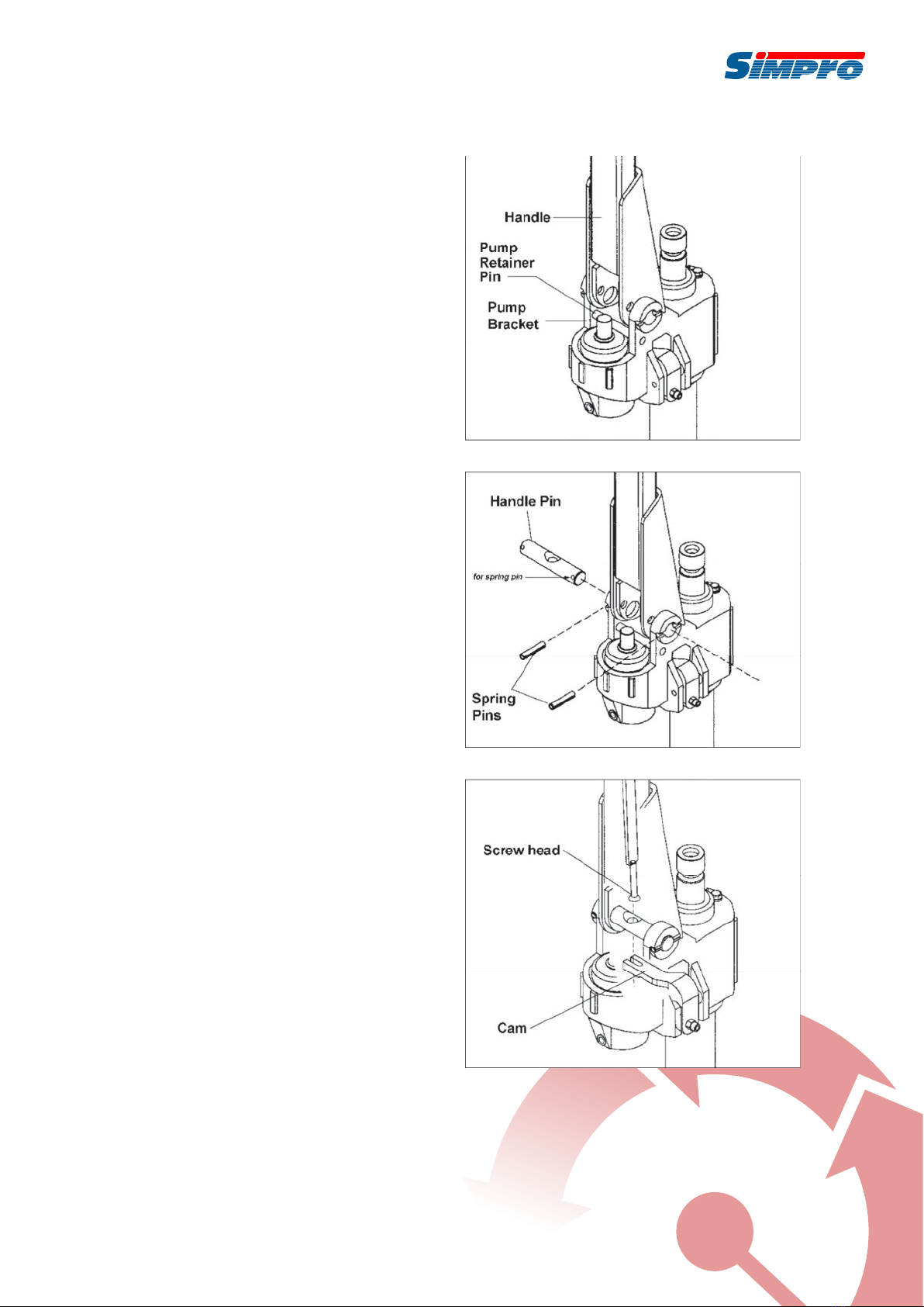
UnpackingOpen shipping container and check for shipping damage. Report any damage immediately to your distributor and shipping agent. Do not discard any shipping material until the Pallet Truck is assembled and working properly.Individual trucks are assembled and ready to use. Pallet trucks purchased in crate quantities (6 units to a crate) require some assembly. Match the letter label on the handle assembly tothe letter label on the frame prior to assembly.AssemblyTools required for assembly: HammerFlat Head Screwdriver Pliers1.Insert the base of the handle into the pump bracket (Figure 1). Align the holes at the base of the handle with the holes in the pump bracket.2.Use a hammer to tap the handle pin into the holes of the pump bracket and handle (Figure 2). Use pliers to turn the handle pin until its holes align with the spring pin holes.3.Feed the screw head through the center hole in the handle pin (Figure 3). Using a screwdriver, pry up the cam and slip the screw head under the notch in the cam.4.Use a hammer to tap the spring pins (Figure2)into the holes on the pump bracket and handle pin.5.Tap out the pump retainer pin (Figure 1). NOTE: It is a good idea to remove any air bubbles that might have accumulated in the hydraulic system during shipping. Refer to Cleaning the Release Valve, on page 3.OperationFigure 1Figure 2Figure 3Smart Lifting
This pallet truck is designed for use with open style pallets or skids only. Closed style pallets must be placed on top of fork prior to use.1. Insert the forks into the pallet.Owner’s Manual // M25 Series Pallet TruckOriginal Version // English // v1.0 // January 2021 // Page 3

2.To raise the fork, push control lever all the way down, and pump the handle until the desired fork height is reached.3.To move the handle without aecting the fork setting, set the control lever in the center neutral position. The load can now be pushed or pulled using the handle.4.To lower the fork, pull lever all the way up. Allow the load to descend slowly in a controlled manner. The lever is spring loaded and will return to the neutral position when released.When not in use, do not allow heavy loads to remain on the fork for an extended period of time. Always lower fork completely when not in use.Up-Down Cam AdjustmentWhen pumping the handle with the lever in neutral position, there should be no movement of the fork. If there is fork movement, the cam must be adjusted:1.Place lever in neutral position.2.Loosen the hex nut .3.Adjust the socket head cap screw while pumping the handle, until there is no longer any movement of the ram.4.Tighten the hex nut .Cleaning the Release Valve (Bleeding the Pump)Over time, the hydraulic pump may become clogged with debris or air bubbles causing improper function.Clean the release valve as follows:1.Pump handle quickly, raising pallet truck to full extent. Pull lever all the way up in order to lower the fork, while continuing to pump the handle.2.When fork has lowered completely, the valve has been ushed. Repeat if necessary.MaintenanceCheck the oil level annually by removing the oil plug on top of the pump housing. When changing or adding oil, ll the tank through the oil plug hole to 80% capacity with hydraulic jack oil, about 2-1/2 deep in pump housing. See Figure 4. Do not use any other type of oil. When nished, replace oil plug .Figure 4Wheel bearings are sealed and require no lubrication. The crank shaft features oil lite bushings that also require no lubrication.Lightly oil all other moving parts.Seal and O-Ring Replacement for Ramand Plunger Piston1.Raise the pallet truck by pumping handle.2.Remove spring pin . This will free the pump and handle assembly from the pallet truck.3.Remove the oil plug , turn pump over andempty the oil into a suitable container. Pump handle until all oil has drained. Dispose of used hydraulic oil according to local disposal regulations.4.Pull out plunger piston and/or ram piston .5.Remove all o-rings and seals. See Figure 5.6.Insert new o-ring or seal one at a time makingsure to replace with the same size that was removed.Reassemble and ll the oil tank through the oil plug hole to 80% capacity with new hydraulic jackoil, about 2-1/2 deep in pump housing. See Figure 4.Figure 53635 34l

TroubleshootingTroubleProbable CauseRemedyHydraulic unit does not lift.Oil level is low.Make sure there is no oil leakage from Release Screw , Pressure Adjustment Screw or valve area. Then add oil.Air in pump.See Cleaning the Release Valve.Worn o-ring in ram cylinder.Replace o-ring (refer to Seal and O-Ring Replacement).Once lifted, truck lowers by itself.Steel ball has not seated in hydraulic unit.See Cleaning the Release Valve.Worn o-ring in ram cylinder.Replace o-ring (refer to Seal and O-Ring Replacement).Release valve not seated properly. See Cleaning the Release Valve. Pallet truck loaded beyond capacity. Reduce load to within capacity.Release valve not adjusted properly.Adjust valve by Pressure Adjustment Screw and Release Screw .Oil leakage from Release Screw or Pressure Adjustment Screw .Tighten Release Screw . Replace o-rings on Release Screw and/orPressure Adjustment Screw. If leakage continues, contact authorized service center.Fork does not lower.Cam requires adjustment.Refer to Up-Down Cam Adjustment.Cam is damaged.Replace cam .Damaged push rods and/or linkages.Replace damaged parts. (It is recommended that an authorized service center perform this work.)Lever does not set at NEUTRAL position.Cam requires adjustment.Refer to Up-Down Cam Adjustment.Smart LiftingOwner’s Manual // M25 Series Pallet TruckOriginal Version // English // v1.0 // January 2021 // Page 5
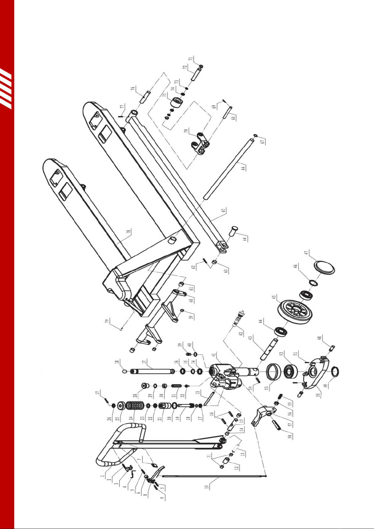
Parts Diagram: M25 Series Pallet Truck

Parts List: M25 Series Pallet TruckNO.DESCRIPTIONQUANTITY1H A N D LE T U B E12ELA ST IC PIN13BLA DE S PR IN G14SPRING15ELA ST IC PIN26ROLLER17LE VER M AT18HANDLE19ELA S TIC PIN110PU LL ROD111OIL LITE B U SH ING212P RE SSU RE R OLLE R113SHAFT114OIL LITE B U SH ING215SHAFT116ELA ST IC PIN217U-PACKING118OIL B AFFE WASHE R119P LUNG E R P IS TO N120O-RING121P LUNG E R H OUS IN G122U-PACKING123D U S T SEAL RIN G124SPRING125S PRIN G CAP126C A LATHIF O RM PAD127R OU ND P IN128R E LE ASE PL UG129O-RING130R E LE ASE SC RE W131SPRING132N E ED LE VAL VE133PIN134U-PACKING135O-RING136D U S T SEAL RIN G137R A M P ISTO N138S TEE L BALL139OIL P LUG140O-RING141P U M P H O US IN G AS SY142VAL VE ASSE MBL Y143S T EE RING WH EEL A XLE S HAFT144BALL B EARIN G445S T EE RING WH EE L246S NAP R IN G247D U S T SEAL CAP248T A B LE P IN2Smart LiftingOwner’s Manual // M25 Series Pallet TruckOriginal Version // English // v1.0 // January 2021 // Page 7

49SNAP RING150TABLE151SPRING PIN252BALL BEARING153BEARIN G BASE154SPRING PIN155SOCKE T HEAD CAP SCREW156HEX NUT157CAM158SPRING PIN159O IL LIT E BUSHING260LIFT ING YO KE161O IL LIT E BUSHING262SPRIN G PIN263O IL LIT E BUSHING264CRANK PIN265PUSH RO D266CRANK SHAFT167SNAP RIN G268ARM PIN269SPRING PIN270LO AD WHEEL FRAME271SNAP R ING472LO AD WHEEL AXLE273FLAT WASHER474BALL BEARING475LO AD WHEEL276ROD PIN277SPRIN G PIN278FO RK FRAME1Parts List continued: M25 Series Pallet Truck

Smart LiftingOwner’s Manual // M25 Series Pallet TruckOriginal Version // English // v1.0 // January 2021 // Page 9

Simpro has been manufacturing and retailing smart lifting solutions for over thirty years.From humble beginnings as a small engineering firm in Auckland, New Zealand, the company has grown to become a leading supplier of handling equipment for niche applications – such as bin-lifting, tipping and handling machines, crate stackers and goods lifts.Simpro products play an unobtrusive but essential role for thousands of companies around the world, in industries as diverse as waste management, food processing,resource extraction and pharmaceutical manufacturing. They are available through a network of agents which spans the globe, and are backed by a sophisticated in-house design and fabrication capability.Simpro is a family-owned company, registered with the New Zealand Companies Office as Simpro Handling Equipment Ltd, company no. 1827916.The products in this document may contain intellectual property, including design elements registered to or licensed by Simpro Handling Equipment Ltd.66 Rangi Road Takanini2105 Auckland,New ZealandPO Box 202236 Southgate, Takanini 2246 Auckland, New Zealandshop.simpro.worldsales@simpro.world+64 9 634 7445Owner’s Manual // M25 Series Pallet TruckOriginal Version // English // v1.0 // January 2021Smart Lifting@SimproWorld_Lifters@simpro.world
Table of contents
Popular Truck manuals by other brands


Hitachi
Hitachi EH3500ACII Operator's manual

Peterbilt
Peterbilt 535 user manual

Komatsu
Komatsu HM400-1 manual

Einhell Global
Einhell Global PHW 2002 operating instructions

PFAFF silberblau
PFAFF silberblau SILVERLINE HU 20-115 BTS operating instructions

UniCarriers
UniCarriers PLL Series Instruction handbook