Simpson Electric 14510-2 User manual
Simpson 14510-2
Volt-Ohm-Milliammeter
OPERATOR’S MANUAL

2
About this Manual
To the best of our knowledge and at the time written, the information con-
tained in this document is technically correct and the procedures accurate
and adequate to operate this instrument in compliance with its original ad-
vertised specifications.
Notes and Safety Information
This Operator’s Manual contains warning symbols which alert the user to
check for hazardous conditions.These appear throughout this manual where
applicable, and are defined below. To ensure the safety of operating perfor-
mance of this instrument, these instructions must be adhered to.
!
Warning, refer to accompanying documents.
Caution, risk of electric shock.
This instrument is designed to prevent accidental shock to the operator when
properly used. However, no engineering design can render safe an instru-
ment which is used carelessly. Therefore, this manual must be read carefully
and completely before making any measurements. Failure to follow direc-
tions can result in a serious or fatal accident.
!
Technical Assistance
SIMPSON ELECTRIC COMPANY offers assistance Monday through Friday
7:30 am to 5:00 pm Central Time. To receive assistance contact Technical
Support or Customer Service at (847) 697-2260.
Internet: http://www.simpsonelectric.com
Warranty and Returns
SIMPSON ELECTRIC COMPANY warrants each instrument and other articles
manufactured by it to be free from defects in material and workmanship un-
der normal use and service, its obligation under this warranty being limited to
making good at its factory or other article of equipment which shall within one
(1) year after delivery of such instrument or other article of equipment to the
original purchaser be returned intact to it, or to one of its authorized service
centers, with transportation charges prepaid, and which its examination shall
disclose to its satisfaction to have been thus defective; this warranty being
expressly in lieu of all other warranties expressed or implied and of all other
obligations or liabilities on its part, and SIMPSON ELECTRIC COMPANY nei-
ther assumes nor authorizes any other persons to assume for it any other
liability in connection with the sales of its products.
SHOCK HAZARD:
As defined in American National Standard, C39.5,
Safety
Requirements for Electrical & Electronic Measuring & Controlling Instrumen-
tation
, a shock hazard shall be considered to exist at any part involving a
potential in excess of 30 volts RMS (sine wave) or 42.4 volts DC or peak and
where a leakage current from that part to ground exceeds 0.5 milliampere,

3
when measured with an appropriate measuring instrument defined in Sec-
tion 11.6.1 of ANSI C39.5.
NOTE: The proper measuring instrument for the measurement of leakage
current consists essentially of a network of a 1500 ohm non-inductive resistor
shunted by a 0.15 microfarad capacitor connected between the terminals of
the measuring instrument. The leakage current is that portion of the current
that flows through the resistor. The Simpson Model 229-Series 2 AC Leak-
age Current Tester meets the ANSI C39.5 requirements for the measurement
of AC leakage current and can be used for this purpose. To measure DC
Leakage current, connect a 1500 ohm non-inductive resistor in series with a
Simpson 0-500 DC microammeter and use this as the measuring instrument.
Multi-function instruments such as the 14510-2 are intended as general pur-
pose measuring instruments for use in relatively low power 120/240 V AC or
dry battery operated circuits such as found in consumer appliances, home
entertainment equipment or general laboratory applications.Some high power
circuits, however, are within its measurement range and present an arcing/
explosion hazard in the event of an unanticipated circuit behavior, a defective
measuring instrument or of an operator error if the operator has not recog-
nized the hazard and observed appropriate personal protective measures.
Such high power circuits that would be within the measuring range of this
Instrument would be found in commercial or industrial equipment operating
from AC and DC supply circuits above 240 V, storage battery banks, or cir-
cuits containing large capacitors. Measurements in such circuits should only
be performed by personnel trained to recognize the hazards and using ap-
propriate safety measures.The Safety Precautions in Section IV are intended
to alert the operator to the more commonly encountered hazards and protec-
tive measures to avoid them.The dangers in high power circuits are serious.
Do not take safety precautions lightly.
NOTE: Any circuit containing voltages exceeding 30 V AC or 60 V DC should
be considered to be a possible shock hazard, and contact with the circuit
should be avoided while the circuit is energized.

4
NOTES

5
NOTES

6
Contents
1. INTRODUCTION................................................................................ 7
1.1 General ...............................................................................................7
1.2 Description .........................................................................................7
1.3 Items And Accessories .......................................................................7
1.4 Technical Data ....................................................................................8
1.5 Definition Of Accuracy ........................................................................9
1.6 Safety Consideration ..........................................................................9
2. PREPARATION FORUSE............................................................... 10
2.1 Unpacking And Inspection ...............................................................10
2.2 Warranty............................................................................................10
2.3 Shipping ...........................................................................................10
2.4 Power Source Requirements ...........................................................10
3. CONTROLS,JACKSANDINDICATOR............................................ 11
3.1 Front Panel .......................................................................................11
4. OPERATION.................................................................................... 12
4.1 Safety Precautions............................................................................12
4.2 Measuring DC Voltages ...................................................................14
4.3 Measuring AC Voltages ....................................................................14
4.4 Measuring Direct Current .................................................................15
4.5 Measuring Resistances....................................................................16
5. OPERATOR MAINTENANCE .......................................................... 17
5.1 Inspection .........................................................................................17
5.2 Battery And Fuse Access .................................................................17
5.3 Battery Replacement........................................................................18
5.4 Fuse Replacement ...........................................................................18
5.5 Care ..................................................................................................19
6. SERVICING INSTRUCTIONS.......................................................... 20
6.1 Replacement Part Table for 14510-2 ...............................................20
6.2 Schematic Diagram, 14510-2 Volt-Ohm-Milliammeter.....................22

7
1. INTRODUCTION
1.1 General
The Simpson 14510-2 Volt-Ohm-Milliammeter (hereinafter referred to as the
14510-2 or the Instrument) is a portable instrument, suitable for the telephone
industries.This instrument is designed for the service person who values true
portability, reliability, simplicity and ruggedness. The Instrument can be ap-
plied in both permanent and mobile installations.
The 14510-2 features reverse safety-style jacks, an easy-to-read dial, a large
range switch knob and an attractive color clutter-free panel.
1.2 Description
The case is made of high-impact (ABS) plastic and is contemporarily styled.
The Instrument is battery operated for the resistance ranges, and fuse and
diode overload protected, with a self-shielded taut-band movement.The taut-
band suspension provides a high degree of repeatability and is highly resis-
tant to shock and vibrations helping to ensure the accuracy and life of the
Instrument. A handle, attached to the sides of the case, allows the Instrument
to be used in either a vertical or horizontal position.The horizontal position is
preferred for greater accuracy since the Instrument is calibrated in that posi-
tion.
1.3 Items And Accessories
All applicable items and accessories required to operate the 14510-2 are
furnished with the Instrument and are listed in Table 1-1. Additional accesso-
ries are listed in Table 1-2.Available replacement parts are listed in Table 6-1.
Table 1-1. Accessories furnished with the Instrument
Quantity Description Number
1 Test Lead Set 00043
*2 15 Volt Cell, NEDA 208 1-111010
*1 1.5 Volt, D Cell, NEDA 13F 1-111798
1 Operator’s Manual 6-114022
* Readily available through local retail stores.
Table 1-2. Additional Accessories
Description Number
Utility Vinyl Carrying Case 00549
Vinyl Carrying Case 01818
Ever-Redy Vinyl Carrying Case 00805
Deluxe Carrying Case 00812
There are three batteries in the ohmmeter circuits. One is a NEDA 13F cell
that furnishes 1.5 volts for the RX1, RX10, RX100 and RX1000 ranges.Two
are NEDA 208 cells that furnish 30 volts required for the RX10,000 range.
The batteries are readily available and replacement is accomplished easily.
Most of the component parts are mounted on a printed circuit board which

8
simplifies assembly and maintenance, thus extending the useful life of the
Instrument.
Each Instrument is furnished with one pair of probe type test leads (one red
and one black, each 48 inches long, Catalog No. 00043) for all Instrument
applications. These test leads have elbow plugs on one end to connect the
leads to the recessed jacks on the Instrument front panel. The probe tips at
the opposite end have threaded shoulders to accept the screw-on insulated
alligator clips (furnished with the test leads).The test leads and the insulated
alligator clips are rated for the voltage and current ranges available on the
14510-2. Maximum ratings are 100 V AC or DC or 10 DC amperes.
These ratings for the test leads must not be exceeded in any application.
1.4 Technical Data
Table 1-3 lists the Technical Data for the 14510-2
Table 1-3
1. DCVOLTS
Ranges: 0.3 V, 3 V, 12 V, 60 V, 300 V, 600 V
Sensitivity: 20 k⍀/volt ranges except on the 0.3 V range, 16 k⍀/volt.
Accuracy: ⫾2% of full scale (FS) all ranges, except on the 0.3 V range,
which on the 0.275 V mark (red line) is ⫾0.5% of FS.
2. ACVOLTS
Range Frequency Response (Hz) Accuracy % of FS
3 V 20 Hz - 100 kHz ⫾1% ⫾3
12 V 20 Hz - 100 kHz ⫾1% ⫾3
60 V 20 Hz - 40 kHz ⫾1% ⫾3
300 V 20 Hz - 10 kHz ⫾2% ⫾3
600 V 20 Hz - 5 kHz ⫾1% ⫾3
Sensitivity: 3 k⍀/volt
Indication: Full wave average responding. Calibrated in rms for
sinusoidal wave forms.
3. DC CURRENT
Range Accuracy % of FS Voltage Drop
0.06 mA ⫾2 300 mV ⫾2%
1.2 mA ⫾2 149 mV nominal
12 mA ⫾2 166 mV nominal
120 mA ⫾2 341 mV nominal
!

9
4. RESISTANCE Battery Voltage Battery Current
Range Midscale Reading (Nominal) (Nominal)
RX1 20 ⍀1.5 V 75 mA
RX10 200 ⍀1.5 V 7.5 mA
RX100 2 k ⍀1.5 V 0.75 mA
RX1000 20 k ⍀1.5 V 0.075 mA
RX10,000 200 k ⍀30 V 0.15 mA
Accuracy: ⫾2% of FS angular deflection at midscale.
5. Reference Conditions: 25°C ⫾2°C, 45 to 75% relative humidity
6. Movement: Taut-band 100° arc, 50 µA FS
7. Dial Arcs: One arc each for ⍀and DC, two arcs for AC
8. Overload Protection: Meter movement by varistor, ranges fused
1/2 A, 250 V in series with 2 A, 600 V
9. Operating Temperature
Ranges (to maintain
rated accuracy): 57°F - 97°F
10. Size: 7" H x 4-1/4" W x 3-1/8" D
11. Weight: Approximately 2-1/2 lbs. with batteries
(1.133 kg)
12. Rated Circuit-to-
Ground*: 600 V AC/DC maximum
* Per ANSI C39.5 April1974:“The maximum voltage,withrespecttoground,
which may safely and continuously be applied to the circuits of an instru-
ment.”
1.5 Definition Of Accuracy
The voltage and current accuracy of the Instrument is commonly expressed
as a percent of full scale.This should not be confused with accuracy of read-
ing (indication).For example, ⫾2% of full scale on the 10 volt range allows an
error of ⫾0.20 V at any point on the dial. This means that at full scale, the
accuracy of reading would be ⫾2%, but at half scale it would be ⫾4%.There-
fore, it is advantageous to select a range which gives an indication as near as
possible to full scale.
1.6 Safety Consideration
This Operator’s Manual contains special caution and warning symbols to alert
the user to hazardous operating and servicing conditions. These symbols
appear throughout this publication where applicable and are defined on the
inside front cover of this manual under SAFETY SYMBOLS. Adhere to these
instructions in order to ensure the safety of operating and servicing person-
nel and to retain the operating performance of this Instrument.

10
2. PREPARATION FOR USE
This section contains instructions for preparing the new Instrument for use.
Also included are unpacking and inspection procedures, warranty, shipping,
and power source requirements.
2.1 Unpacking And Inspection
Examine the shipping carton for signs of damage before unpacking. If the
carton is in good condition, unpack and inspect the Instrument and packing
materials for possible damage incurred during shipment. If damage is noted,
notify the carrier and supplier and do not attempt further use of the Instru-
ment. If the Instrument appears to be in good condition, read the Operator’s
Manual in its entirety. Become familiar with the Instrument as instructed in the
manual, then check the electrical performance. Also check to see that all fur-
nished items and accessories are included (Table 1-1). Save the shipping
carton and packing material for future storing or shipping of the Instrument.
After unpacking the Instrument, a 1.5V battery and two 15V batteries may be
found in separate envelopes in the box with the Instrument and test leads.
Two alligator clips for the test leads are in a polyethylene bag. (See Section 5
for instructions on how to open the battery compartment and install the bat-
teries.)
2.2 Warranty
The Simpson Electric Company warranty policy is printed on the inside front
cover of this manual.Read it carefully before requesting any warranty repairs.
NOTE: For all assistance, including help with the Instrument under warranty,
contact the nearest Authorized Service Center for instructions. If necessary,
contact the factory directly. Give full details of any difficulty, the Instrument
model number, series number and date of purchase. Service data or ship-
ping instructions will be mailed promptly. If an estimate of charges for non-
warranty or other service work is required, a maximum charge estimate will
be quoted. This charge will not be exceeded without prior approval.
2.3 Shipping
Pack the Instrument carefully and ship it prepaid and insured.
2.4 Power Source Requirements
There are three batteries in the ohmmeter circuits. One is a NEDA 13F cell
that furnishes 1.5 volts for all ranges except RX10,000 range.Two NEDA 208
cells furnish 30 volts for the RX10,000 range. Weak batteries should be re-
placed promptly . Replace with the same type batteries as supplied with the
Instrument. (See Table 1-1.)

11
3. CONTROLS, JACKS AND INDICATOR
The purpose and use of the 14510-2 front panel controls and its features are
described below. Become familiar with each control and its function before
using the Instrument.
3.1 Front Panel
Item numbers in Table 3-1 correspond with identifying numbers in Figure 3-1.
Table 3-1. Controls, Jacks and Indicator
1. Meter: ThismeteriscalibratedforACvoltage(rms), DC volt-
age, current and resistance. Some scales are read
directly while others require a multiplying factor.
2. Range Switch: The range switch has 21 positions. It may be turned
to any position from either direction.There are eleven
voltage positions, four direct current positions, five
resistance positions and an OFF position.
3. Ohms Adjust: The ohms adjust control is a variable resistor in the
ohmmeter circuit, which permits adjustment to “0”for
the ohms ranges.
4. Circuit Jacks: There are two jacks located on the front panel.These
are the connections for the test leads. The elbow
prods of the test leads are plugged into the proper
jacks. Negative (–) black to (⍀) jack, positive (+) red
lead to (+) jack.
Figure 3-1. Simpson 14510-2 Front Panel

12
5. Pointer Adjust for
Zero With the Instrument in an operating position, check
that the pointer indicates zero at the left end of the
scale when there is no input. If pointer is off zero,
adjust the screw located in the cover below the cen-
ter of the dial. Use a small screwdriver to turn the
screw slowly clockwise or counterclockwise until the
pointer is exactly over the zero mark at the left end of
the scale.With the indicating pointer set on the zero
mark, reverse the direction of rotation of the zero
adjuster a sufficient amount to introduce mechani-
cal freedom or “play” but an insufficient amount to
disturb the position of the indicating pointer.This pro-
cedure will avoid disturbances to the zero setting by
subsequent changes in temperature, humidity, vibra-
tion and other environmental conditions.
4. OPERATION
Beforeattempting tooperatethisInstrument, refertoWARNINGoninside front
cover of this manual.
Information required to use and operate the 14510-2 in the proper manner
follows below:
The test leads are provided with accessory screw-on alligator clips which
may be attached to the probe tips. Eliminating the need to hand-hold test
probes to a circuit for extended periods, the test clips also reduce hand prox-
imity to a high voltage circuit while energized. Circuit power must, of course,
be turned off and any charged capacitors discharged before connecting or
disconnecting clips to or from the circuit. Replacement of test leads, when
necessary, should be of the exact style supplied with the Instrument.
NOTE: All measurements are made with the black test lead connected to the
(⍀) jack and the red test lead to the (+) jack.
Before making any measurements, check to see that the pointer indicates
zero, when the Instrument is in the operating position.If the pointer is off zero,
use a small screwdriver to turn the screw located directly above the range
switch in either direction until the pointer rests at zero. (See Section 3, Con-
trols, Jack and Indicator.)
4.1 Safety Precautions
NOTE: The following precautions are suggestions and reminders of com-
monly recognized safe practices to be used and specific hazards to be avoided
and are not implied to be sufficient to ensure the safety of untrained person-
nel in all circumstances.Neither is this manual a substitute for technical manu-
als covering the equipment in which measurements are to be made. Always
!

13
refer to the equipment manual and its specific warnings and instructions, and
observe them as well as those contained herein.
1. The 14510-2 should only be used by personnel qualified to recognize
shock hazards and trained in the safety precautions required to avoid
possible injury.
2. Do not connect any terminal of this Instrument to a circuit point at which a
voltage exceeding 600 volts AC or DC may exist with respect to earth
ground. (Refer to Table 1-3, item 12.)
3. This Instrument is intended only for use indoors or in sheltered locations.
To prevent fire or shock hazards, do not expose it to rain or moisture.
Condensation may occur when the Instrument is moved from a cold area
to a warm area. DO NOT ATTEMPT HIGHVOLTAGE MEASUREMENTS
UNTIL CERTAINTHAT THE INSTRUMENT HAS DRIEDTHOROUGHLY.
4. Turn off power and discharge any capacitors in the circuit to be mea-
sured before connecting to or disconnecting from it.
5. Before using this Instrument, check accessories (if any) and test leads
for missing, damaged, deteriorated or otherwise faulty insulating parts.
Do not use, or permit the use of, equipment with faulty insulation until it
has been properly repaired.
IMPORTANT:
6. Always wear safety glasses when working with electrical circuitry.
7. Do not work alone on high voltage circuits. Make certain that someone
capable of rendering aid is nearby and aware.
8. Do not handle the Instrument, its test leads or the circuitry while taking
any measurements.
9. Be sure to reset the range switch to the OFF position after completing
resistance or current measurements.This is to prevent inadvertent appli-
cation of high voltage to the resistance or current ranges when the In-
strument is next used.
10. Hands, shoes, floor and workbench must be dry. Avoid measurements
under humid, damp or other environmental conditions that could affect
the dielectric withstanding voltage of the test leads of the Instrument.
11. Do not change switch settings or test lead connectionswhile the circuit is
energized. A mistake could result in damage to the Instrument and pos-
sible personal injury.
12. Locate all voltage sources and accessible current paths before making
connections to circuitry.
NOTE: Voltage may appear unexpectedly or in unexpected locations in faulty
equipment. An open bleeder resistor, for example, may result in a capacitor
retaining a dangerous charge.
13. Make certain that the equipment being worked upon is properly grounded
and fuses are of the proper type and rating.
14. Check and double check switch positions and jack connections before
applying power to the Instrument.
15. Always remain alert for low voltage circuits which may be floating at high
voltage with respect to earth ground and for composite voltages (AC +
DC) such as are found in rf amplifiers.The floating voltage or composite

14
voltagemustnotexceedtheInstrument’s rated maximum circuit-to-ground
voltage. (See Table 1-3, item 12.)
16. Do not make electrical measurements where the air may contain explo-
sive concentrations of gas or dust such as in mines, grain elevators, gaso-
line stations or in the presence of charging batteries, until determined to
be safe by qualified personnel. Note that even metallic dust can be ex-
plosive.
17. No general purpose VOM is to be used to make measurements on blast-
ing circuits or blasting caps. Use only designated instruments.
Be extremely careful when working with high voltage circuits. Even though
the Instrument and test leads are well insulated for protection of the operator,
it is not advisable to handle either when power is on in the circuit.
4.2 Measuring DC Voltages
1. Set the range switch at one of the six voltage range positions marked 0.3
V, 3 V, 12 V, 60 V, 300 V or 600 V. When in doubt about the approximate
voltage present, start with the highest voltage range to protect the Instru-
ment.If the voltage reading is within the limits of a lower range, the switch
then may be set to that range to obtain a more accurate reading.
2. Be sure the power is off in the circuit to be measured and all capacitors
have been discharged.
3. Connect the black test lead to the negative side of the circuit being mea-
sured and the red test lead to the positive side of the circuit.
4. Turn on the power of the circuit and read the voltage on the black scale
marked AC-DC. For the 0.3 V and the 3 V ranges, use the 0-300 figures
and divide the reading by 1000 and 100 respectively. For the 12 V, 60 V
and 300 V ranges read the figures directly. For the 600 V range, use the
0-60 figures and multiply the reading by 10.
5. Turn the power off, disconnect the test leads and return the range switch
to the OFF position.
4.3 Measuring AC Voltages
NOTE: The rectifier circuit in the 14510-2 responds to the full-wave rectified
average value of an AC waveform.The Instrument is calibrated in terms of the
rms value of a pure sine wave which will be correct for all sinusoidal wave-
forms. If the waveform is non-sinusoidal, the reading could result in a sub-
stantial error. Also, accuracy is lessened at higher input frequencies.
NOTE: Since the VOM will respond to DC voltage when set on any AC volt-
age range, an external blocking capacitor must be employed where mea-
surements of AC superimposed on DC are encountered.
1. Set the range switch at one of the five voltage range positions marked 3
V, 12 V, 60 V, 300 V or 600 V. When in doubt about the approximate volt-
age in the circuit being measured, start with the highest voltage range as
!
15
a protection to the Instrument. If the voltage is within a lower range, the
switch then may be set at a lower range to obtain a more accurate read-
ing.
2. Be sure the power is off in the circuit being measured and all the capaci-
tors have been discharged.
3. Connect the test lead across the voltage source with the black lead on
the ground side.
4. Turn on the power in the circuit being measured and read the voltage on
the red scale marked AC.
5. For the 3V range, read the value directly on the red scale marked 3V AC.
Forthe12V, 60V, 300 V and 600V ranges,readontheblackscale marked
AC-DC. For the 12V, 60V and 300V ranges, read the figures directly. For
the 600 V range, use the 0-60 figures and multiply the reading by 10.
6. Turn power off, disconnect the test leads and return the range switch to
the OFF position.
4.4 Measuring Direct Current
Never connect the test leads of this Instrument directly across any source of
voltage when it is used for current measurements. This will damage the In-
strument.
NOTE: The voltage drop will not significantly affect most circuits whose cur-
rent is being measured. In some low voltage circuits, such as transistor cir-
cuits, it may be necessary to take the voltage drop into account when making
current measurements. (See Table 1-3, Current Ranges.)
Do not switch any range or function settings on the Instrument and never
disconnect the test leads from the circuit while the circuit under measurement
is energized. When the circuit is de-energized, discharge all the capacitors.
Never exceed the circuit-to-ground voltage of the Instrument, 600V max.(See
Table 1-3, item 4.12.)
In all current measurements, be certain that the power to the circuit under test
has been turned off before restoring circuit continuity.
1. Set the range switch at one of the four range positions marked 0.06 mA,
1.2 mA, 12 mA or 120 mA. Always start with the highest range first.
2. Turn the power off, discharge all capacitors and open the circuit in which
the current is to be measured. Connect the Instrument in series with the
circuit. Connect the red test lead to the positive side and the black test
lead to the negative side of the circuit.
3. Turn on the power to the circuit under test.
!
!

16
4. Read the current in milliamperes on the black AC-DC scales. For the
0.06 mA range, use the 0-60 scale and divide the reading by 1000. For
the 1.2 mA range, use the 0-12 scale and divide the reading by 10. For
12 mA range, use 0-12 scale and read directly. For the 120 mA range,
use 0-12 scale and multiply readings by 10.
5. Upon completion of all readings, turn off power to the circuit and remove
test leads from circuit.
6. IMPORTANT:Return range switch to the OFF position when current mea-
surements are completed.
4.5 Measuring Resistances
Before making resistance measurements, remove all power to the circuit un-
der test and discharge all capacitors.
When DC resistances are measured, the internal batteries of the Instrument
furnish power for the measuring circuit.The zero adjust control provides cor-
rection for battery deterioration over long periods of time.
1. Set the range switch to the desired resistance range position.
2. Connect the probe ends of the test leads together (short tips together).
3. Observe the Instrument indication. It should read “0” on the ohms arc,
which is at the top of the dial.
4. If the pointer does not read “0”, rotate the V Adj. (Zero Adjust Control)
knob either direction until it does read “0”.If the pointer cannot be brought
up to the “0” mark, replace the appropriate battery (1.5 V for low ranges
and two 15 V for the high range — refer to paragraph 5.3 for battery re-
placement).
Do not apply any power to the circuit before measurements are completed
and the test leads are disconnected.
5. Connect the test leads across the resistance which is to be measured. If
there is a “forward” and “backward” resistance, such as with diodes, ob-
serve the polarity in the lead connections to control each test.The resis-
tance should be relatively low when the diode is forward biased by the
battery potential and higher in the opposite direction.
When checking diodes and semiconductors do not use the RX1000 or
RX10,000 ranges. Using these ranges may result in permanent damage to
component being checked.
6. Read the indication of the OHMS arc at the top of the dial. Note that the
arc reads from right to left for increasing values.
7. Multiply the reading by the multiplier factor indicated at the switch posi-
!

17
tion; the result is the resistance value in ohms. (“K” on the dial and panel
stands for “one thousand.”)
NOTE: The resistance of nonlinear components will measure differently from
one resistance range to another. For example: a diode could measure 80
ohms on the RX1 range and 300 ohms on the RX10 range.The difference in
the reading is a result of the non-linear diode characteristic and does not
indicate faulty operation of the ohmmeter circuit.
8. Disconnect ends of test leads and return the range switch to the OFF
position after resistance measurements are completed.
5. OPERATOR MAINTENANCE
This section describes those functions necessary to maintain the Instrument
in an operating condition and which may be performed by the operator or
user. This Instrument is carefully designed and constructed with high quality
components. By providing reasonable care and following instructions in this
manual, the user can expect a long, useful service life of the Instrument.
Servicing, other than that which is described in this Section, should be per-
formed only by qualified personnel, by one of the Authorized Service Centers
or by the factory.
5.1 Inspection
The user is protected from electrical shock by the insulation of the Instrument
and the test leads. Frequent examination of each should be made for any
insulation damage, such as cracks, cuts, chips, burns or deterioration that
expose internal metal parts or conductors, or any reduction in spacing be-
tween such metal and hand contact by the user. Replacement leads should
be the same as those originally supplied with the Instrument and can be ob-
tained from one of the Authorized Service Centers or the factory.
To avoid electrical shock, disconnect test leads from live circuits and from the
Instrument before opening the battery compartment cover.
5.2 Battery And Fuse Access
The batteries and 1/2-ampere fuse are located inside an isolated compart-
ment at the top-rear of the Instrument case. To open the compartment, pro-
ceed as follows:
Place the Instrument face down on a soft padded surface and unscrew the
single captivated screw on the compartment cover. Remove the cover from
the case and set it aside. Batteries and fuse now can be replaced.
NOTE: If replacement of the 2-amp high current interrupting fuse is neces-
sary, the Instrument case must also be removed (see paragraph 5.5 and Fig-
ure 5-2).
!
18
5.3 Battery Replacement
Battery replacement is indicated when the pointer cannot be adjusted to zero
on a resistance range.
Remove the battery compartment cover (paragraph 5.3). If zero cannot be
adjustedontheRX1, RX10, RX100 or RX1000 ranges,the1.5V battery needs
replacement. Replace with a 1.5 V, NEDA 13F, “D” size cell. If zero cannot be
adjusted on the RX10,000 range, one or both 15 V batteries need replace-
ment. (It is suggested that both batteries be replaced at the same time.) Re-
place with 15 V NEDA 208 battery, Burgess U10, Eveready 411, Ray-O-Vac
208, or equivalent.
Replace the battery compartment cover.
5.4 Fuse Replacement
Fuse replacement is indicated when the Instrument is completely inoperative
in all functions.
The 1/2 A, 250 V fuse is accessible inside the battery compartment. Remove
the battery compartment cover (paragraph 5.3).Carefully pry the fuse from its
clips and replace with an exact replacement.Do not substitute a different type
fuse or rating.It may not serve its purpose and may cause the internal fuse to
blow unnecessarily next time. Replace with a 1/2 A, 250 V Quick Acting
Littlefuse Type 3AG, Catalog No. 312.500, or equivalent.
NOTE: A spare has been provided in the compartment adjacent to the work-
ing fuse as an emergency replacement. If the spare is used, replace it as
soon as possible to assure that it will again be available in an emergency.
If the Instrument now operates (check it in a resistance range by shorting the
testleads together), replace the compartment cover.If the Instrumentstill does
not operate, the internal fuse may be open. For access to this fuse, the case
back must be removed.
++
WARNING
To avoid electrical shock, make certain that test leads are disconnected from any circuits
before removing covers.
NOTE: If instrument fails to operate after replacing fuse (F1) check and replace (F2) inside
case, if required, before returning for repair.See Operator's Manual.No other user serviceable
parts inside. Refer servicing to qualified personnel only.
CARELESSNESS AND MISUSE OF THIS INSTRUMENT CAN BE DANGEROUS
Before connecting this instrument, carefully read the instructions and precautions in the
Operator's Manual. Failure to do so can result in a serious or fatal injury.
SAFETYTIPS
1. Do not attempt any measurements unless trained, qualified and authorized to do so.
2. Do not connect to any circuit where the voltage with respect to ground earth may exceed
1000 volts.
Whenever making measurements with this instrument:
a. Turn off circuit power and discharge any capacitance in the circuit before connectin
or disconnecting test leads or changing switch settings.
b. Double-check for correct swtich settings and test lead connections before applying
power.
c. Do not touch the instrument, test leads or the circuit while power is ON.
d. Do not use any instrument or test leads that are damaged, contaminated, deteriorated,
moist, or which have missing parts.
4. Voltages as low as 30 volts r.m.s. or 42.4 volts peak can render an electric shock.
5. Read the Operator's Manual for additional precautions and instructions.
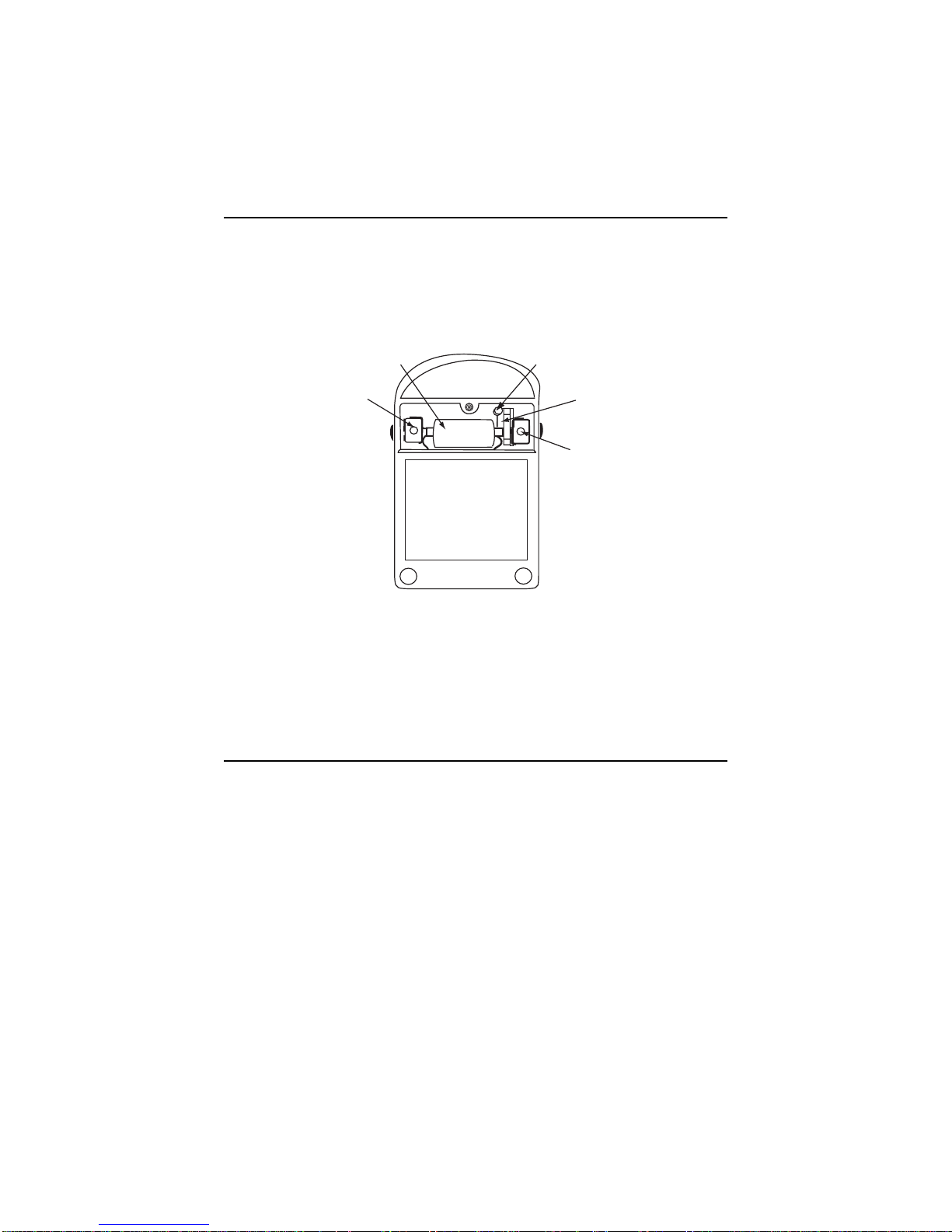
¯¯
1.5V
Battery
15V
Battery
Spare Fuse
1/2 A, 250V
Fuse (F1)
15V
Battery
Figure 5-1. Battery and Fuse Compartment

19
1. Remove the battery compartment cover. Place the Instrument face-down
on a soft, padded surface. Loosen the four screws at the four corners of
the case back and lift the case back off of the Instrument.
Figure 5-2. Location of 2 Amp Fuse
2. Take care not to disturb any internal components or wiring. Do not at-
tempt any servicing beyond fuse replacement unless qualified to do so.
Improper repairs may endanger the user of this Instrument.Refer to sec-
tion 5, SERVICING INSTRUCTIONS.
3. Carefully pry the fuse from its clips and replace it with an exact replace-
ment. Do not substitute a different type fuse or rating as it may not serve
its special purpose. Replace only with a Littlefuse Type BLS or Bussman
type BBS, 2 A, 600V.
4 Shake the unit gently to make certain that no loose debris is left inside.
Replace the case back and tighten the four screws. Replace the battery
compartment cover.
5.5 Care
1. For insulation to remain effective, keep clean and dry at all times. For
normal grime, use a mild detergent and a damp cloth to clean the Instru-
ment and dry thoroughly before use.DO NOT PERMIT LIQUIDSTO EN-
TERTHE CASE.
2. Immediately clean all spilled materials from the surface of the Instrument
and wipe dry. If the spillage is corrosive, use a suitable cleaner to neu-
tralize the corrosive action.
3. When the Instrument is not in use, rotate the function switch to the OFF
position.
4. Whenever possible, avoid prolonged exposure or usage in areas which
15V Battery
Front Panel
2 Amp Fuse
!

20
are subject to temperature and humidity extremes, vibration or mechani-
cal shock, dust or corrosive fumes, or strong electrical or electromag-
netic interferences.
5. On a monthly basis, verify Instrument accuracy by performing operational
checks using known, accurate and stable sources. If proper calibration
equipment is not available, contact the nearest Authorized Service Cen-
ter. If the Instrument has not been used for 30 days, check the batteries
for leakage and replace if necessary.
6. It is recommended that the Instrument be returned annually to the near-
est Authorized Service Center, or to the factory for an overall check, ad-
justment and calibration.
7. When the Instrument is not in use, store in a room free from temperature
extremes,dust,corrosivefumesandmechanicalvibrationorshock.If stor-
age time is expected to exceed 30 days, remove batteries.
8. When an Instrument must be stored and/or transported in a vehicle in
very cold weather, it will be subject to condensation when brought into a
warm building.Therefore, do not attempt high voltage measurements until
the Instrument has had time to dry completely.
6. SERVICING INSTRUCTIONS
An improperly repaired instrument may be dangerous to the user.This Instru-
ment contains no user-serviceable parts other than the batteries and fuses.
Do not attempt any other repairs or parts replacement unless trained and
qualified to do so. The contents of this section are provided only for use by
such qualified repairmen. Refer repairs to the factory or to one of the Autho-
rized Service Centers.
Table 6-1 lists the replacement parts for the 14510-2 and the ordering part
numbers. Replacement parts and accessory items may be ordered from the
factory or from any Authorized Service Center.
6.1 Replacement PartTable for 14510-2
Table 6.1. Replacement Parts for 14510-2
Symbol Description Part No.
B1, B2 15 V Battery 1-111010
B3 1.5 V Battery 1-111798
D1, D2 Diode, Germanium, 1N100 1-115970
R2 Resistor, 27 k⍀, 1%, 1/2 W 1-110282
R3 Rheostat, 100 k⍀, 10%, 1/2 W 5-119020
R4, R5 Rheostat, 1 k⍀, 10%, 1.5W,W.W. 5-117967
R6 Resistor, 1.3 ⍀V, 1%, 1/2 W 5-118990
R9 Rheostat, 2 k⍀, 10%, 1.5W, W.W. 5-116716
R10 Resistor, 4.5 k⍀, 1%, 1/2 W 5-118983
R11 Resistor, 27 k⍀, 1%, 1/2 W 1-110282
Table of contents
Other Simpson Electric Measuring Instrument manuals


