Simpson 42115 User manual
www.simpsongroup.com
Operating Instructions
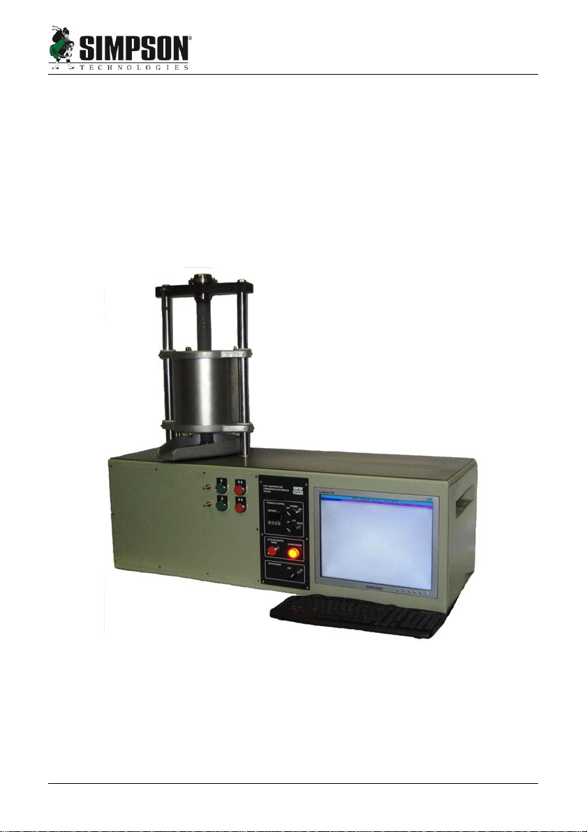
High Temperature Compression Tester
Model 42115

www.simpsongroup.com
Type:
High Temperature Compression
Tester
Model:
42115
Part No.:
0042115-ASM
0042115-220-ASM
Serial Number:
Name and address of manufacturer:
Simpson Technologies Corporation
751 Shoreline Drive
Aurora, IL 60504
For other Simpson Technologies offices around the world and for our
contact information please visit us on the internet at
www.simpsongroup.com on the Contacts page.
This document is strictly confidential.
This document is protected under the copyright laws of the United States and other countries as an
unpublished work. This document contains information that is proprietary and confidential to
Simpson Technologies Corporation or its subsidiaries which shall not be disclosed outside or
duplicated, used or disclosed in whole or in part for any purpose other than to evaluate Simpson
Technologies for a proposed transaction. Any use or disclosure in whole or in part of this information
without the express written permission of Simpson Technologies Corporation is prohibited.
© 2021 Simpson Technologies Corporation. All rights reserved.

Table of Contents
man-stc-42115-V15-27 Sand Rammer i
Table of Contents
1Introduction.......................................................................... 1
1.1 Application and Designated Use ...................................................1
1.2 Organizational Measures................................................................1
2Safety.................................................................................... 2
2.1 Safety Signs and Labels.................................................................2
2.1.1 Safety Alert Symbols ...........................................................................3
2.1.2 Safety Symbol Labels..........................................................................4
2.2Lockout and Tagout System Procedures .....................................7
2.3 Lockout and Tagout Devices..........................................................7
2.3.1 Glossary: ............................................................................................. 8
3Short Description & Specifications.................................... 9
3.1 Description.......................................................................................9
3.1.1 Components Description ..................................................................... 9
3.2 The High Temperature Compression Tester includes: .............11
4Unpacking and Installation............................................... 13
4.1 Unpacking ......................................................................................13
4.2 Components...................................................................................14
4.3 Installation......................................................................................15
4.4 Electrical Power Requirements....................................................15
4.5 Set-up..............................................................................................16
4.5.1 Connecting the High Temperature Compression Tester and the
Cooling Tank-Pump Assembly............................................................................ 16
4.6 Airborne Noise Emission..............................................................18
5Operating Instructions...................................................... 19
5.1 Performing a High Temperature Compression Test..................20

Table of Contents
ii Sand Rammer man-stc-42115-V15-27
5.2 Test Descriptions and Operation.................................................21
5.2.1 RL Test (Restraining Load Test)........................................................ 21
5.2.2 (EX) Test (Expansion Test) ............................................................... 27
5.2.3 S&D Test (Strength and Deformation)............................................... 29
6Maintenance and Calibration............................................ 38
6.1 Maintenance...................................................................................38
6.2 Calibration......................................................................................38
6.2.1 Force Calibration ............................................................................... 39
6.2.2 Displacement Calibration................................................................... 44
7Parts List / Ordering Parts / Returns................................ 46
7.1 Spare Parts List .............................................................................46
7.2 Ordering Replacement / Spare Parts...........................................46
7.3 Returned Goods Policy.................................................................47
8Decommissioning.............................................................. 49

Table of Contents
man-stc-42115-V15-27 Sand Rammer iii
This Page Is Intentionally Blank.


1 Introduction 1
man-stc-42115-V15-27 Sand Rammer 1
1 Introduction
Congratulations, you have just purchased an extremely reliable sand
testing instrument that is backed by the professional technical support
and years of proven sand technology experience of Simpson
Technologies Corporation.
This laboratory equipment is constructed of quality materials and is the
result of unsurpassed craftsmanship. The High Temperature
Compression Tester should be operated only when it is in perfect
condition and in accordance with its designed purpose, with the operator
aware of possible hazards. Observe the Safety instructions in Section 2
and Operating Instructions in Section 5.
1.1 Application and Designated Use
The High Temperature Compression Tester, Model 42115, is used to
determine hot properties of molded sand with any type of binder
(kaolinites, bentonites and chemical binders). The equipment operates
with both; the American Foundry Society standard specimens (1.125”
(28.58mm) diameter X 2” (50.8mm) high) and the Metric standard
specimens (11.28 mm diameter X 20 mm high).Any other application
outside the intended usage will be regarded as use not in accordance
with its purpose, and, therefore, the manufacturer / supplier will not held
liable for any damage that might arise thereunder. The risk in this case
will be exclusively that of the User.
1.2 Organizational Measures
The operating instructions should be readily available at the place of
operation. In addition to the operating instructions, the general legal
regulations or other mandatory rules for prevention of accidents and
environmental protection should be made known and be observed!
The personnel instructed to use this apparatus, before beginning work,
should have studied and fully understood these Operating Instructions, in
particular the Safety chapter.
No modifications, extensions or changes of design of the device that
would impact safety requirements should be put into effect with prior
consent of the supplier! Spare parts must conform to the technical
specifications defined by the manufacturer. This is always guaranteed
when using original spares.

Safety 2
2 Sand Rammer man-stc-42115-V15-27
2 Safety
Before operating and/or performing maintenance or
repair on Simpson Technologies Corporation
designed and/or manufactured equipment, it is
required that all personnel have read and
understood the entire Operation Maintenance
manual. If any questions exist, you must contact
your supervisor or Simpson Technologies
Corporation before taking further action.
If properly operated and maintained, your Simpson Technologies
Corporation supplied equipment can provide many years of
dependable and safe operation. Please follow all recommended
safety, operating, and maintenance instructions. Furthermore, the
introduction of any non-Simpson Technologies Corporation
manufactured and/or approved parts to the equipment may create a
hazardous situation. Never alter the equipment without prior
consultation with Simpson Technologies Corporation.
DO NOT use this machine for purposes other than that for
which it was intended. Improper use could result in death
or serious injury.
2.1 Safety Signs and Labels
Simpson Technologies has incorporated the ANSI Z535.6 / ISO 3864-
1-2 safety symbol only label format on all of its laboratory equipment.
For the location of the safety labels on your equipment, refer to the
"Location of Nameplate and Decals" drawing in Section 10.
The harmonized ANSI Z535.6 format became an established safety
label format since it not only fully meets the current ANSI Z535
standards, but also incorporates ISO 3864-2 symbology and hazard
severity panel and thus, can be used for both the U.S. and
international markets.

2 Safety
man-stc-42115-V15-27 Sand Rammer 3
2.1.1 Safety Alert Symbols
This is the safety alert symbol. It is used to alert you to
potential personal injury hazards. OBEY all safety
messages that follow this symbol to avoid possible injury
or death.
DANGER! Indicates an imminently hazardous
situation which, if not avoided, will result in
death or serious injury.
The safety alert symbol used without a signal
word to call attention to safety messages
indicates a potentially hazardous situation
which, if not avoided, could or may result in
death or minor to serious injury.
NOTICE indicates information used to address
practices not related to personal injuries but
mayresult in property damage.
This symbol indicates information containing important instructions
concerning the use of the machine or directions for further
procedures. Ignoring this information can lead to malfunction of the
machine.

Safety 2
4 Sand Rammer man-stc-42115-V15-27
2.1.2 Safety Symbol Labels
DO NOT TOUCH - HOT SURFACE (STC #214045)
This label is located on the High Pedestal Support and in the
Specimen Tray
While performing a test or calibrating the Sand Rammer; the ramming
weight free falls, striking the anvil every time the main cam completes
one revolution while preparing a sand specimen. Also, when placing
the anvil with the weight in the upper position for calibrating or
housekeeping purposes, the weight and anvil will free fall if the
auxiliary cam is not in the locked position, which may crush or cut
body parts if Safety System Procedures are not followed. When
performing any maintenance, the anvil and weight must rest on the
frame; this will put the sand rammer into Zero Mechanical State
(ZMS).
ELECTRICAL SHOCK / ELECTROCUTION
(STC #214043)
This label is located on the rear panel of the control cabinet
and in the furnace junction box
When the front panel or any other panels from the control panel or the
junction box cover are removed, electrical terminals are exposed. A
hazardous voltage is present, can cause electric shock or burn, and
may result in serious injury or death. Follow Lockout and Tagout
procedures before servicing.

2 Safety
man-stc-42115-V15-27 Sand Rammer 5
EXPLOSION / RELEASE OF PRESSURE
(STC #217945)
This label is located on the back panel of the unit by the pneumatic
tubing connections.
With pneumatic pressure present, disconnecting or cutting the
pneumatic tubing will release the pressure contained within the tubing.
Blown-out air with or without solid particles in the air stream may get
into the eyes and may irritate or damage the eye. Follow Lockout and
Tagout procedures before servicing.
EXPLOSION / RELEASE OF PRESSURE
(STC #217945)
This label is located on the left front panel of the High Temperature
Compression Tester
The High Temperature Compression Tester sliding furnace and
adjoining parts are extremely hot. Contact may result in serious burns
to skin. DO NOT TOUCH unless protective gloves are worn. Follow
Lockout and Tagout procedures and allow surface to cool before
servicing.

Safety 2
6 Sand Rammer man-stc-42115-V15-27
WEAR SAFETY GOGGLES
(STC #205308)
This label is located on the left front panel of the High Temperature
Compression Tester
When operating the High Temperature Compression Tester, the sand
specimen may break before, during or after the test and sand may
blow-off to the surroundings and get into the eyes and may irritate
and/or damage the eye. Follow Lockout and Tagout procedures
before servicing.
READ AND UNDERSTAND ALL SERVICE MANUAL
INSTRUCTIONS
(STC #214081)
This label is located on the left front panel of the High Temperature
Compression Tester
Before operating and/or performing any maintenance or repair on
Simpson Technologies Corporation designed and/or manufactured
equipment, it is required that all personnel read and understand the
entire Operating Instructions manual. If any questions exist, you must
contact your Supervisor or Simpson Technologies Corporation before
taking further action. Follow Safety System Procedures before
servicing.

2 Safety
man-stc-42115-V15-27 Sand Rammer 7
2.2 Lockout and Tagout System Procedures
Whenever performing any type of maintenance or
repair, whether in the form of cleaning, inspection,
adjustment or mechanical maintenance, the
equipment must be rendered into Zero
Mechanical State (ZMS).
Prior to any maintenance (routine or otherwise) or repair of
equipment, a safety procedure should be established and maintained.
This procedure should include training of personnel; identification and
labeling of all equipment which is interlocked mechanically, through
levers, gravity or otherwise; and a listing of the established
procedures posted on each equipment.
"Lockout and Tagout" refers to specific practices and procedures to
safeguard personnel from the unexpected energizing of machinery
and equipment, or the release of hazardous energy during service or
maintenance activities. This requires, in part, that a designated
individual turns off and disconnects the machinery or equipment from
its energy source(s) before performing service or maintenance, and
that the authorized employee(s) lock or tag the energy-isolating
device(s) to prevent the release of hazardous energy and take steps
to verify that the energy has been isolated effectively.
2.3 Lockout and Tagout Devices
When attached to an energy-isolating device, both lockout and tagout
devices are tools used to help protect personnel from hazardous
energy. The lockout device provides protection by holding the energy-
isolating device in the safe position, thus preventing the machine or
equipment from becoming energized. The tagout device does so by
identifying the energy-isolating device as a source of potential danger;
it indicates that the energy-isolating device and the equipment being
controlled may not be ordered until the tagout device is removed.

Safety 2
8 Sand Rammer man-stc-42115-V15-27
2.3.1 Glossary:
Authorized Person(s) - Personnel who have been designated by
his/her department to perform maintenance or service on a piece(s)
of equipment, machinery or system, and are qualified to perform the
work through proper training on the Lockout/Tagout procedures for
the equipment, machinery or system.
Lockout - The placement of a lockout device on an energy isolating
device, in accordance with an established procedure, to ensure that
the energy isolating device and the equipment being con- trolled
cannot be operated until the lockout device is removed.
Lockout Device - Any device that uses positive methods, such as a
lock (either key or combination type), to hold an energy isolating
device in a safe position, thereby preventing the energizing of
machinery or equipment. When properly installed, a blank flange or
bolted slip blind are considered equivalent to lockout devices.
Tagout - The placement of a tagout device on an energy isolating
device, in accordance with an established procedure, to indicate that
the energy isolating device and the equipment being con- trolled may
not be operated until the tagout device is removed.
Tagout Device - Any prominent warning device, such as a tag and a
means of attachment that can be securely fastened to an energy
isolating device in accordance with an established procedure. The
tag indicates that the machine or equipment to which it is attached is
not to be operated until the tagout device is removed in accordance
with the energy control procedure.
Zero Mechanical State - The mechanical potential energy of all
portions of the equipment or machine is set so that the opening of
pipes, tubes or hoses, and the actuation of any valve, lever or button,
will not produce a movement which could cause injury.

3 Short Description & Specifications
man-stc-42115-V15-27 Sand Rammer 9
3 Short Description & Specifications
3.1 Description
The High Temperature Compression Tester is used to determine the
hot properties of clay and/or chemically bonded sand specimens. An
electronic load cell and displacement sensor measures hot
compressive strength, hot deformation, expansion, and restraining
load at elevated temperatures. The test results are displayed on a
color monitor. The resultant data can be printed and/or stored into the
memory of the instrument. When determining hot compression
strength, the instrument generates and displays a complete stress-
strain curve, and also shows the maximum compressive strength,
deformation at maximum strength and maximum deformation. The
display also indicates the real time strength and deformation of the
sand specimen. An accurate digital controller and indicator regulate
the furnace temperature. The furnace is capable of maintaining
temperatures up to 2000o F (1093o C). An automatic timer controls
the specimen heating time and activates the press at the end of the
selected soak time.
3.1.1 Components Description
Hydro-pneumatic press: With incrementing regulated speed and
controlled:
1. Automatically, during the hot compression and deformation
tests.
2. Manually, by means of electric pushbuttons to rapidly position
the lower pedestal up or down or slowly adjust lower pedestal
ascent or descent when the expansion and stress at
restrained load tests are performed. The manual mode is also
employed during machine calibration.

Short Description & Specifications 3
10 Sand Rammer man-stc-42115-V15-27
The Furnace: The furnace is powered by a transformer and a solid-
state relay and heated by a 1700 watts electric resistance heating
element. A quartz tube isolates the heating element from the working
area which consists of the specimen and upper and lower pedestals.
A digital temperature controller regulates the temperature of the
furnace. The furnace is raised vertically by a pneumatic piston. If a
power failure is experienced the furnace rises up automatically and
remains in that position. A safety system stops the heating of the
furnace and raises the furnace whenever coolant flow is lost and/or
the coolant plate temperature goes up.
Max operating temperature for this machine is
1900F. Temperatures above this can cause
damage to the furnace and claims under guarantee
will no longer be considered.
A safety system stops heating the furnace and raises it whenever
coolant flow is lost and/or the coolant plate temperature goes up.
Load Measurement: Loads are measured by an electronic load cell
with capacity up to 5000 Newton. A coolant plate is positioned
between the load cell and bushing to help avoid any transmission of
heat through the lower pedestal to the electronic load cell. The signals
that the load cell sends are displayed on the LCD screen either as
specific resistance value (N/cm2 or PSI), or as force (Newton or
pounds), depending on the test and the standard used.
Deformation Measurement: By means of a displacement transducer
directly mounted on the pushing ram of the hydro pneumatic press.
The displacement readings allow deformation appreciations of:
For metric specimen (h=20 mm): 0.031%
For the AFS specimen (h=50.8 mm): 0.012%
Computer: Industrial PC with monitor and keyboard. The operator
selects the type of test and test standards with the keyboard.
Each test is displayed in (Real Time) and maximum values on a user
friendly screen.

3 Short Description & Specifications
man-stc-42115-V15-27 Sand Rammer 11
3.2 The High Temperature Compression Tester includes:
One printer, 3 sets of specimen supports, pneumatic Filter-Regulator-
Lubricator (FRL), pneumatic hose and connectors to connect the
supplied FRL to the instrument and a cooling tank-pump system.
Specifications, Dimensions and Weights (Approximate)
The loads that act during all high temperature tests are measured by
means of an electronic load cell. The screen displays the specific
forces (resistances) according to the selected standard. When
calibrating the load cell, the screen displays the loads expressed in
Newton (N).
The displacement sensor featured by the apparatus enables it to
measure.
•Hot deformation is the deformation (strain) that the specimen
suffers during the application of load at a determined
temperature.
•Linear expansion is the expansion the specimen experiences
when heated at a determined temperature.
•Restraining load test is the force that must be applied to
prevent the expansion of the specimen when heated to a
determined temperature.

Short Description & Specifications 3
12 Sand Rammer man-stc-42115-V15-27
The equipment consists of:
1. A hydro-pneumatic press that applies a load to the specimen
being tested. The system includes a manual regulating valve
to control the rising speed of the press.
2. A furnace to heat the specimen. The furnace temperature is
regulated by an accurate digital controller and indicator. The
furnace is moved up and down over the prepared specimen
by a pneumatic cylinder.
3. A coolant pump unit that pumps coolant oil through a coolant
plate on the electronic load cell to keep cools the load cell.
4. A digital timer that controls the heating time of the specimen.
At a specified time, the hydro-pneumatic press compresses
the specimen.
5. An electronic load cell that displays digitally the resistance
value.
6. A displacement sensor that measures the positive and/or
negative strain of the specimen.
7. A computer with monitor and keyboard that stores and
processes the test data.
Power: 110/220 V, 50/60 Hz on request, 2 Kw
Pneumatic Connection: Filtered, lubricated and regulated air from 5 -
5.4 bar (72-80 PSI) Filtering, regulating and lubricating air equipment
is supplied.
Specifications
High Temperature Compression Tester
Length
1050mm (41.5”)
Width
430mm (17”)
Height
900mm (35.5”)
Weight
126 kg (278 lbs.)

4 Unpacking and Installation
man-stc-42115-V15-27 Sand Rammer 13
4 Unpacking and Installation
4.1 Unpacking
Your new Laboratory Equipment has been closely
inspected before being shipped to your plant.
However, damage can occur in route, so it is wise
to inspect all equipment on arrival. Notify both the
carrier and Simpson Technologies Corporation of
any damage at once. Damage should be noted on
the shipper's receipt before signing for receipt of the
shipment.
The High Temperature Compression Tester Model 42115 is shipped
in two primary pieces consisting of the High Temperature
Compression Tester apparatus and the Coolant Tank-Pump
Assembly. Both pieces are designed to be connected by a reinforced
PVC hoses. Lifting equipment is required for handling the High
Temperature Compression Tester; the Tester weighs approximately
126 kg (278 lbs.). The Coolant Tank-Pump Assembly due to its bulky
dimensions and tight fitting shipping crate, it is recommended that two
people should be utilized, the approximate dimensions are 305 mm
Dia. x 445 mm H (12” Dia. x 17.5” H) and weight 11.5 Kg. (25 Lbs.).
1. Remove any loose accessories/parts within from the shipping
crate and place in a location away from any packaging
material to assure that these items are not misplaced.
2. Carefully remove the High Temperature Compression Tester
and Coolant Tank-Pump from the packing crate and place on
stable bench.
3. Once removed from the crate, proceed by taking off any
protective wrap and unpackaged the protective material from
the included accessories.
4. The packaging remains the property of the Customer and may
be used for returning the apparatus if some repair is required.

Unpacking and Installation 4
14 Sand Rammer man-stc-42115-V15-27
4.2 Components
Your new High Temperature Compression Tester, Model 42115, is
shipped with the following accessories and installation components.
Please take a moment and identify that the following items are
included:
•Coolant Tank-Pump Assembly.
•Air filter, regulator, lubricator and fittings to connected them
together.
•One 4mm I.D. pneumatic blue tubing, one meter long.
•Two #10 threaded mufflers.
•One male quick connector G1/8 to 4 mm I.D. tubing.
•One pipe adapter G1/8 to1/8 NPT.
•One keyboard.
•One data USB flash drive.
•One service USB flash drive.
•One calibration gage with magnetic base and one calibrating
post.
•One aligning plate.
•Six steel lentils.
If any of the above components are missing, contact your local
Simpson Technologies office.
Do not store the device in the open and
unprotected from atmospheric conditions. If this
instruction is not followed, claims under guarantee
will no longer be considered.
This manual suits for next models
2
Table of contents
Other Simpson Test Equipment manuals


