Simpson 42145 User manual

www.simpsongroup.com
Operating Instructions
Electronic Scratch Hardness Tester
Model 42145
www.simpsongroup.com
Type:
Electronic Scratch Hardness Tester
Model No.:
42145
Part No.:
0042145
Serial No.:
Name and Address of Manufacturer:
Simpson Technologies Corporation
751 Shoreline Drive
Aurora, IL 60504
For other Simpson Technologies offices around the world and for our
contact information please visit us on the internet at
www.simpsongroup.com on the Contacts page.
This document is strictly confidential.
This document is protected under the copyright laws of the United States and other countries as an
unpublished work. This document contains information that is proprietary and confidential to
Simpson Technologies Corporation or its subsidiaries which shall not be disclosed outside or
duplicated, used or disclosed in whole or in part for any purpose other than to evaluate Simpson
Technologies for a proposed transaction. Any use or disclosure in whole or in part of this information
without the express written permission of Simpson Technologies Corporation is prohibited.
© 2021 Simpson Technologies Corporation. All rights reserved.

Table of Contents
man-stc-42145-V17-22 Electronic Scratch Hardness Tester i
Table of Contents
1Introduction 1
1.1 Application and Designated Use ...................................................1
1.2 Organizational Measures................................................................1
2Safety 2
2.1 Safety Alert Symbols ......................................................................2
3Short Description & Specifications 4
3.1 Description.......................................................................................4
3.2 Software Functions.........................................................................4
3.3 Specifications..................................................................................4
4Unpacking and Installation 6
4.1 Unpacking and Parts List...............................................................6
4.2 Preparation - Battery Status...........................................................7
4.3 Installing Software and Connection to PC ...................................7
5Operating Instructions 9
5.1 Description.......................................................................................9
5.2 User Information Screens ............................................................11
5.2.1 User Name Screen Description ............................................11
5.2.2 Current Scale Type Screen Description................................11
5.2.3 Last Calibration Screen Description......................................11
5.2.4 Actual Date/Time Screen Description...................................12
5.3 Setup Description..........................................................................12
5.3.1 Editing User Name................................................................13
5.3.2 Editing Mold Identification Name ..........................................13
5.3.3 Calibration Points..................................................................14
5.3.4 Timer and Battery Status ......................................................14

Table of Contents
ii Electronic Scratch Hardness Tester man-stc-42145-V17-22
5.3.5 Viewing Memory Status - Setup Description ........................15
5.3.6 Exiting Setup Mode...............................................................15
5.4 First Use.........................................................................................16
5.5 Working Modes Screen Description ........................................... 17
5.5.1 Store Data Into Tester Memory ............................................18
5.5.2 Point Mode............................................................................18
5.5.3 Link Mode .............................................................................20
5.6 Input Data to Excel Spreadsheet.................................................21
6Calibration, Maintenance and Warranty 23
6.1 Daily Maintenance.........................................................................23
6.2 When Required..............................................................................23
6.3 Setting Calibration Points............................................................24
6.4 Care for Your Electronic Scratch Hardness Tester...................26
6.5 Warranty, Service and Support ...................................................26
7Parts List / Ordering Parts / Returns 27
7.1 Spare Parts List.............................................................................27
7.2 Ordering Replacement / Spare Parts ..........................................27
7.3 Returned Goods Policy ................................................................ 27
8Decommissioning 30

Introduction 1
man-stc-42145-V17-2 Electronic Scratch Hardness Tester 1
1 Introduction
Congratulations, you have just purchased an extremely reliable sand
testing instrument that is backed by the professional technical support
and years of proven sand technology experience of Simpson
Technologies Corporation.
This laboratory equipment is constructed of quality materials and is
the result of unsurpassed craftsmanship. The Electronic Scratch
Hardness Tester (Model 42145) should be operated only when it is in
perfect condition, in accordance with its designed purpose and being
aware of possible hazards. Observe the safety instructions in Section
2 and operating instructions in Section 5.
1.1 Application and Designated Use
The Electronic Scratch Hardness Tester (Model 42145), is intended
exclusively for measuring the hardness of the core or mold present in
foundry molding sands. Usage of other materials may be possible
upon consultation with the Service department of Simpson
Any other application outside the intended usage will be regarded as
use not in accordance with its purpose, and, therefore, the
manufacturer/supplier will not be held liable for any damage that
might arise thereunder. The risk in this case will be exclusively that of
the user.
1.2 Organizational Measures
The operating instructions should be readily available at the place of
operation. In addition to the operating instructions, the general legal
regulations or other mandatory rules for prevention of accidents and
environmental protection should be made known and be observed!
The personnel instructed to use this apparatus, before beginning
work, should have studied and fully understood these Operating
Instructions, in particular the “Safety” chapter.
No modifications, extensions or changes of design of the device that
would impact safety requirements should be put into effect without
prior consent of the supplier! Spare parts must conform to the
technical specifications defined by the manufacturer. This is always
guaranteed when using original spares.

2 Safety
2Electronic Scratch Hardness Tester man-stc-42145-V17-22
2 Safety
The following Safety Instructions must be studied by
the responsible personnel before commissioning
and adhered to when operating the machine.
2.1 Safety Alert Symbols
This Manual does not imply any guarantee, but just has the intention
of conveying technical information. We reserve the right to modify the
contents of these Operating Instructions.
To facilitate quick comprehension and secure handling the symbols
used in the publication are shown below.
This is the safety alert symbol. It is used to alert you to
potential personal injury hazards. OBEY all safety messages
that follow this symbol to avoid possible injury or death.
Indicates an imminently hazardous
situation which, if not avoided, will result in death or
serious injury.
The safety alert symbol used without a signal word
to call attention to safety messages indicates a
potentially hazardous situation which, if not avoided,
could or may result in death or minor injury.
NOTICE indicates information used to address
practices not related to personal injuries but may
result in property damage.
This symbol indicates information containing important instructions
concerning the use of the machine or directions for further
procedures. Ignoring this information can lead to malfunction of the
machine.

Safety 2
man-stc-42145-V17-2 Electronic Scratch Hardness Tester 3
Use only the battery specified for the tester.
Always safely dispose of the battery according to local regulations.
Never expose battery to direct heat or dispose of it by
incineration!
Improperly using the battery can cause it to leak and damage
nearby items and may cause the risk of fire or personal injury.
We reserve the right to all modifications which do not affect the
technical content of these Operating Instructions.
3 Short Description & Specifications
4Electronic Scratch Hardness Tester man-stc-42145-V17-22
3 Short Description & Specifications
3.1 Description
The scratch hardness of a mold or core is determined using the
Simpson Electronic Scratch Hardness Tester (Model 42145). The
instrument incorporates a four point cutter that penetrates a finished
core or mold surface when rotated. The depth of penetration of the
cutter into the specimen determines the hardness of the core or mold.
The use of advanced electronics increases the accuracy of the
instrument. The Electronic Scratch Hardness Tester is lightweight,
portable and engineered for foundry use.
The instruction will automatically record the hardness number every 360
degrees of cutter rotation. This instrument will display, for a defined
time, the resultant scratch hardness value in the LCD.
3.2 Software Functions
•Store and display date of last calibration
•Store and display user name
•Point to Point mode
•Store up to 900 data points
•Identify up to 32 molds
•Digital calibration of displacement
•Infrared data transfer to computer
3.3 Specifications
Requirements
Electronic Scratch Hardness Tester (42145)
Power
AAA Rechargeable NiMH Battery
(Battery Charger not included)
Software
IBM Compatible, Windows Software

Short Description & Specifications 3
man-stc-42145-V17-2 Electronic Scratch Hardness Tester 5
Dimensions/Weights
Electronic Scratch Hardness Tester (42145)
Length
140 mm (5.5 in.)
Width
64 mm (2.5 in.)
Height
32 mm (1.25 in.)
Weight
Tester only - .25 kg (.55 lbs.)

4 Unpacking and Installation
6Electronic Scratch Hardness Tester man-stc-42145-V17-22
4 Unpacking and Installation
4.1 Unpacking and Parts List
Check the package for transport damages upon receipt and complete-
ness of the order in accordance with the Packing List. Any transport
damages or missing parts should be reported immediately to both the
carrier and equipment supplier.
Protect the device from atmospheric conditions that may be harmful.
Failure to follow this instruction may nullify any claims under warranty.
The following equipment should be included in the package:
(Figure 1)
» Electronic Scratch Hardness Tester Unit
» Infrared IR receiver unit, USB cable
» AAA Battery (Ni-MH rechargeable is included)
» Calibration assembly; including mounting fixture, micrometer and,
aluminum foot (for use in manufacturer’s calibration; call Simpson
for details)
» USB thumb drive (including instructions and drivers to download
data)
» Holster
Figure 1

Unpacking and Installation 4
man-stc-42145-V17-2 Electronic Scratch Hardness Tester 7
4.2 Preparation - Battery Status
The unit comes complete with a rechargeable Ni-MH AAA battery that
can be charged in any standard battery charger (not included). The Ni-
MH battery that comes with the unit should be fully charged according
to the OEM's battery charger (not included) before use. The battery has
a life of 8+ hours and may be recharged a total of 500 times before it
must be replaced.
Use only the battery specified for the tester in this manual.
Always ensure that the positive (+) and negative (-) ends of the
battery are facing correctly when loading battery into the tester.
Always safely dispose of the battery according to local regulations.
Never expose battery to direct heat or dispose of it by
incineration!
Improperly using the battery can cause it to leak and
damage nearby items and may cause the risk of fire or
personal injury.
Figure 2

4 Unpacking and Installation
8Electronic Scratch Hardness Tester man-stc-42145-V17-22
4.3 Installing Software and Connection to PC
1. Insert supplied USB thumb drive into your computer’s USB port and
copy the file Simpson eLab x86 x64 r1 to a convenient location on
your hard drive. If you wish, you can make a shortcut Icon on your
desktop for quick access.
2. Follow the instructions included on the enclosed thumb drive to
transfer the data.
a. Process to verify if PC recognized the USB cable
b. Process to allow to open macros in excel.
c. Process to collect data from the equipment.
3. Save the USB thumb drive as your master for the program file. Do
not link any data to the supplied thumb drive.
4. If you have trouble installing the software, see the back cover for
contacting us.
5. Assemble the cord (Figure 3). The “USB” connector plugs into the
USB port of the PC. Position the IR receiver facing to the Infrared
Data Port from the Tester.
Figure 3: USB Cable and Infrared IR Receiver
Operating Instructions 5
man-stc-42145-V17-2 Electronic Scratch Hardness Tester 9
5 Operating Instructions
For more information on how to use and care for your
Simpson Analytics equipment and accessories visit our
Simpson Technologies channel on YouTube and search
our library of videos. Subscribe to our channel to keep
updated on new releases.
5.1 Description
Scratch hardness of a mold the measurement of the surface hardness
of the mold. This is accomplished by removing material on the surface
of the mold and measuring the depth of penetration.
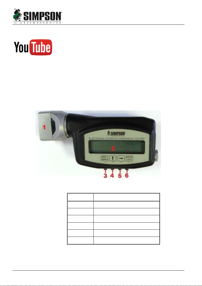
•Refer to Figures 4-6 for location of the various components while
following this instruction manual:
Figure 4
Item
Description
1
Penetrator Head
2
LCD Screen
3
MENU Button
4
UP Button
5
RIGHT Button
6
ENTER Button
5Operating Instructions
10 Electronic Scratch Hardness Tester man-stc-42145-V17-22
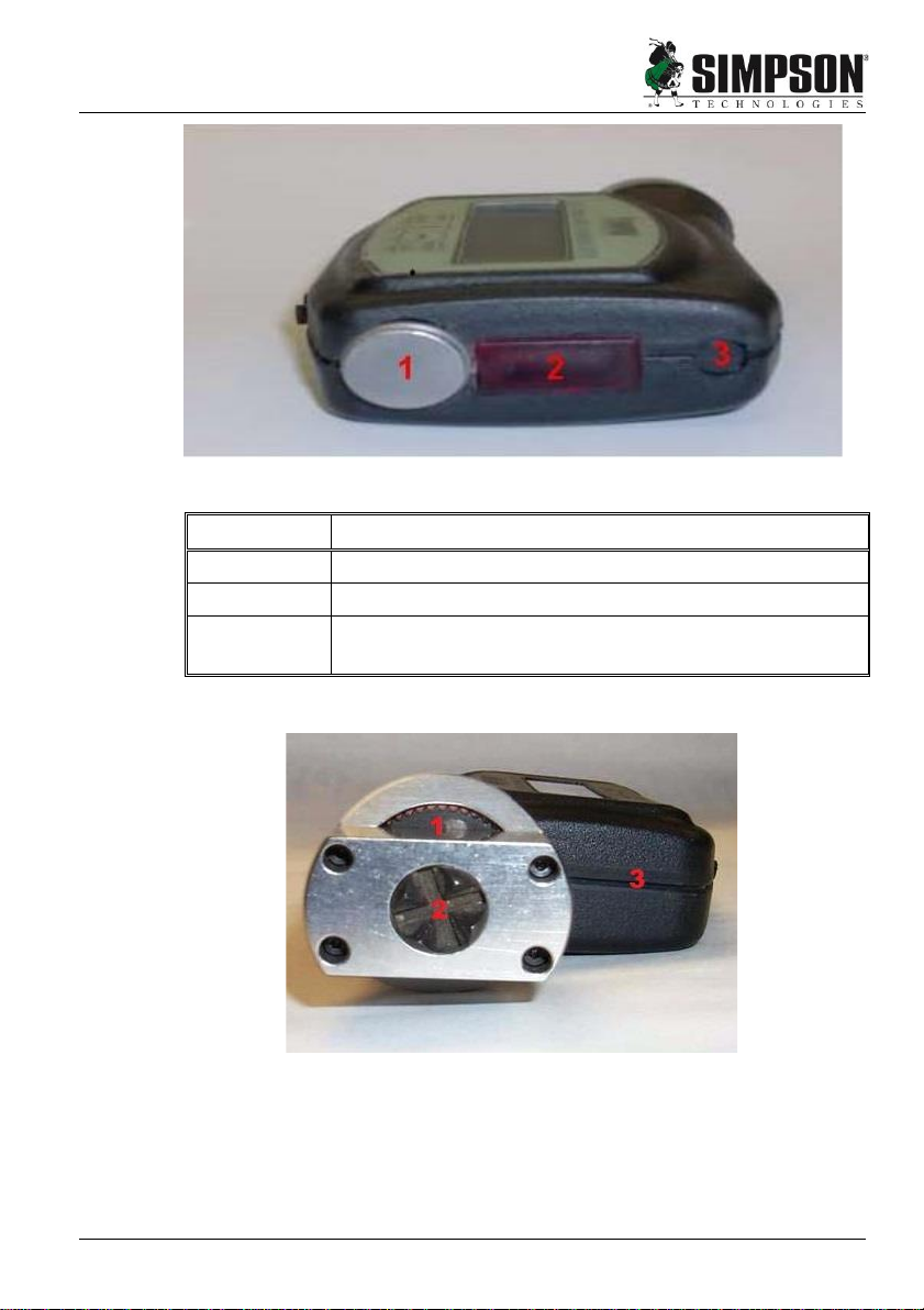
Figure 5
Item
Description
1
Battery Compartment
2
Infrared Data Port
3
Covered Spring Port
(DO NOT REMOVE RUBBER COVER)
Figure 6: Collar (1) Penetrator (2) and Body (3)
Operating Instructions 5
man-stc-42145-V17-2 Electronic Scratch Hardness Tester 11
5.2 User Information Screens
There are five information screens in addition to the work mode screen
(USER NAME-SCALE-CALIBRATION-DATE-WORK). Cycle through
the beginning screens by pressing MENU from the working modes
screen.
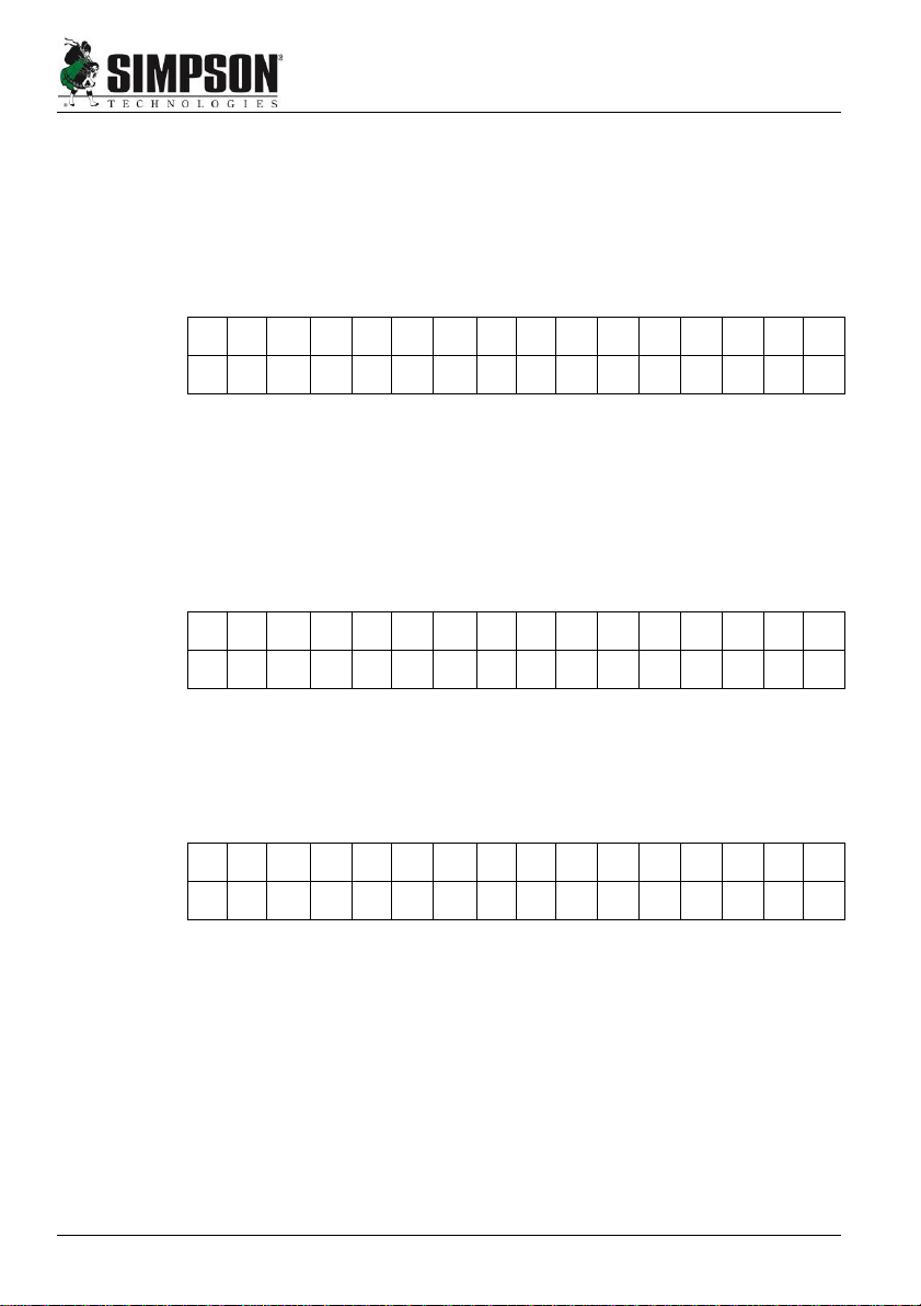
5.2.1 User Name Screen Description
S
I
M
P
S
O
N
-
G
E
R
O
S
A
U
s
e
r
N
a
m
e
Figure 7
1. This screen shows the current user name (Figure 7). The only
function available in this screen is a key combination to enter the
SETUP MODE, see the section on Setup Screens.
2. Press MENU to switch to the next screen.
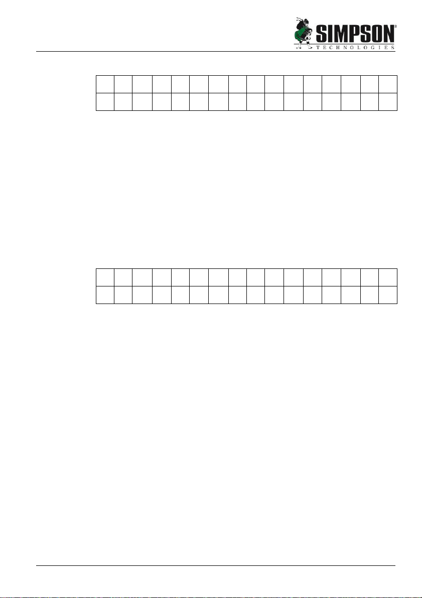
5.2.2 Current Scale Type Screen Description
H
A
R
D
N
E
S
S
T
E
S
T
E
R
C
o
r
e
Figure 8
This screen shows the current scale type (Figure 8). No other function
is available on this screen. Pressing MENU will change to next screen.
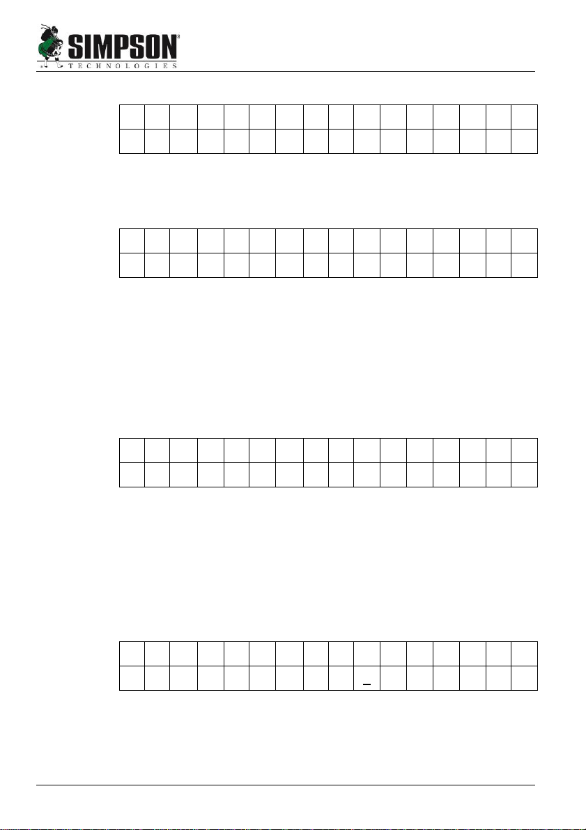
5.2.3 Last Calibration Screen Description
L
A
S
T
C
A
L
I
B
R
A
T
I
O
N
0
4
/
2
6
/
2
0
1
0
1
5
:
3
0
Figure 9
This screen shows when the hardness displacement sensor was last
calibrated (Figure 9). No other function is available on this screen.
Pressing MENU will change to next screen.
5Operating Instructions
12 Electronic Scratch Hardness Tester man-stc-42145-V17-22
5.2.4 Actual Date/Time Screen Description
A
C
T
U
A
L
D
A
T
E
/
T
I
M
E
0
4
/
2
6
/
2
0
1
0
1
5
:
3
0
Figure 10
1. This screen shows the actual time and date (Figure 10). A clock is
embedded into the instrument; its operation is shown by the
flashing colon. Using this screen you may set the date.
2. Press ENTER, a cursor will appear in the left of the screen, under
the month. The UP arrow will increment the number, and the
RIGHT arrow will advance the cursor position.
3. To exit the editing mode, simply press ENTER again.
4. Pressing MENU will return you to work mode screen.
5.3 Setup Description
S
I
M
P
S
O
N
-
G
E
R
O
S
A
U
s
e
r
N
a
m
e
Figure 11
1. Setup has 5 option screens:
USER NAME - MOLD IDENTIFICATION NAME - CALIBRATION -
TIMER AND BATTERY STATUS - MEMORY). You may cycle
through these by pressing the MENU button.
2. Enter setup mode by returning the USER NAME screen (Figure 11).
Hold the UP arrow for four seconds, then hold the RIGHT arrow for
four seconds until the screen changes as below (Figure 12).
Operating Instructions 5
man-stc-42145-V17-2 Electronic Scratch Hardness Tester 13
5.3.1 Editing User Name
E
D
I
T
U
S
E
R
N
A
M
E
U
s
e
r
N
a
m
e
Figure 12
1. To enter the Edit mode, press ENTER and a cursor will appear
(Figure 13).
Figure 13
3. Advance the cursor by pressing the RIGHT arrow.
4. To change the characters, press UP arrow. The characters will
increment by one character, in a cyclical fashion.
5. To increment backwards, press MENU. This will advance in the
reverse direction in a cyclical fashion.
5.3.2 Editing Mold Identification Name
E
D
I
T
M
O
L
D
N
A
M
E
m
o
l
d
0
1
:
0
0
0
0
0
0
Figure 14
1. This screen is available to edit the name given to a particular mold
or pattern number (Figure 14). First, choose a mold number to edit
the name of. There are 32 (00-31) mold numbers to choose from.
2. To increment the current mold number, simply press the UP arrow.
3. In the same way, to decrement the mold number, press the RIGHT
arrow.
E
D
I
T
M
O
L
D
N
A
M
E
m
o
l
d
0
1
:
0
0
0
0
0
0
Figure 15
E
D
I
T
U
S
E
R
N
A
M
E
_
U
s
e
r
N
a
m
e

5Operating Instructions
14 Electronic Scratch Hardness Tester man-stc-42145-V17-22
4. After you choose a mold number, press ENTER to edit a mold
number's name. The cursor should appear under the first character
of the name (Figure 15). To edit the name, proceed as with the
USER NAME screen. You have six characters with which to name a
mold number.
5. Advance the cursor by pressing the RIGHT arrow.
6. To change the characters, press the UP arrow. The characters will
increment by one character, in a cyclical fashion.
7. To increment backwards, press MENU. This will advance in the
reverse direction in a cyclical fashion.
8. Once you enter the complete name, press ENTER again to quit.
9. Pressing MENU will change to next screen.
5.3.3 Calibration Points
See 6.3 of the Calibration and Maintenance.
5.3.4 Timer and Battery Status
A
O
F
T
A
S
T
O
B
A
T
T
3
0
.
0
0
2
0
0
1
.
6
1
Figure 16
1. This screen allows you to adjust two things, AOFT and ASTO.
BATT refers to the battery power left (Figure 16).
2. AOFT is the automatic offset reading. Changing this will clear the
display in more or less time. It is measured in seconds. You can
change the time by pressing ENTER. This cycles the time by 0.5
seconds from 18.0 to 0.0.
3. ASTO is the number of the minimum reading before the timer is
activated. Increase the value by pressing the UP button. Decrease
the value by pressing the RIGHT button. There is one decimal
point in the number, for example 0200 is 20.0. This is your
minimum reading.
Operating Instructions 5
man-stc-42145-V17-2 Electronic Scratch Hardness Tester 15
4. BATT shows the remaining battery power. The battery may be
recharged up to 500 times; after this, it must be replaced. This
allows you to monitor the battery’s charge.
5. Press MENU to change to next screen.
5.3.5 Viewing Memory Status - Setup Description
M
E
m
o
r
y
U
S
e
d
0
3
2
0
M
E
m
o
r
y
L
E
f
t
7
3
6
0
Figure 17
1. This shows the amount of memory used, and how much memory is
free (Figure 17). The total amount of memory is 7680 bytes (960
readings!) for intensive sampling.
If you press RIGHT, you reset the memory. This will erase the sample
information stored in the onboard memory. Use extreme care not to
reset the memory, unless you purposely intend to clear the memory.
2. REMEMBER!!! If you press RIGHT, like the SERIAL IRED LINK,
you will be given a prompt warning that the memory will be lost.
Therefore, use extreme care not to reset the memory unless you
purposely intend to clear the memory (Figure 18).
M
e
m
o
r
y
U
S
e
d
0
0
0
0
M
e
m
o
r
y
L
E
f
t
7
6
8
0
Figure 18
5.3.6 Exiting Setup Mode
To exit the SETUP MODE, you must cycle through all of the setup
screens. After you have reached the memory screen, pressing MENU
once more will get the screen out of setup and to the User Name screen
and the instrument will return to normal operation.

5Operating Instructions
16 Electronic Scratch Hardness Tester man-stc-42145-V17-22
5.4 First Use
S
I
M
P
S
O
N
-
G
E
R
O
S
A
U
s
e
R
N
a
m
e
Figure 19
1. Turn the instrument on by pressing the ENTER button. Hold
ENTER for at least 3 seconds to stabilize the power supply.
If the unit does not seem to respond to a button, hold it in for a
moment.
2. The unit will display a series of screens, beginning with the one
shown in Figure 19 above and changing at a rate of about 2
seconds. It will cycle through these until it reaches the fifth screen;
that is the work mode screen.
If you press any key before the cycle is done, the cycle will stop, press
MENU until you reach the work mode screen. Begin when the cursor
is flashing. On the LCD screen, only the option above the flashing cur-
sor may be edited.
3. Button operation: In order to complete any operation, a button
should be held until the operation is performed.
The hardness tester will turn itself off, except when the work mode
flag is on Wk, after five minutes of inactivity for conserving battery
power. The charge can be monitored in the Setup mode, Timer and
Battery Status. The tester will not turn itself off in the Timer and
Battery Status mode.
Table of contents
Other Simpson Test Equipment manuals


Popular Test Equipment manuals by other brands

Klein Tools
Klein Tools HVNCVT1 instruction manual

TIS
TIS 851 instruction manual

WIKA
WIKA CEP6500 operating instructions

Würth
Würth PRO II LCD Translation of the original operating instructions

Industrial Test Systems
Industrial Test Systems eXact iDip quick start guide

Rigol
Rigol MSO2000A Series user guide


