Simpson 385-3L User manual

Model 385 3L, V2
Temperature Tester
OPERATOR’S MANUAL

2
About this Manual
To the best of our knowledge and at the time written, the information con-
tained in this document is technically correct and the procedures accurate
and adequate to operate this instrument in compliance with its original ad-
vertised specifications.
Notes and Safety Information
This Operator’s Manual contains warning symbols which alert the user to
check for hazardous conditions. These appear throughout this manual where
applicable, and are defined below. To ensure the safety of operating perfor-
mance of this instrument, these instructions must be adhered to.
!
Warning, refer to accompanying documents.
Caution, risk of electric shock.
This instrument is designed to prevent accidental shock to the operator when
properly used. However, no engineering design can render safe an instru-
ment which is used carelessly. Therefore, this manual must be read carefully
and completely before making any measurements. Failure to follow direc-
tions can result in a serious or fatal accident.
!
Technical Assistance
SIMPSON ELECTRIC COMPANY offers assistance Monday through Friday
7:30 am to 5:00 pm Central Time. To receive assistance contact Technical
Support or Customer Service at (847) 697-2260.
Internet: http://www.simpsonelectric.com
Warranty and Returns
SIMPSON ELECTRIC COMPANY warrants each instrument and other articles
manufactured by it to be free from defects in material and workmanship un-
der normal use and service, its obligation under this warranty being limited to
making good at its factory or other article of equipment which shall within one
(1) year after delivery of such instrument or other article of equipment to the
original purchaser be returned intact to it, or to one of its authorized service
centers, with transportation charges prepaid, and which its examination shall
disclose to its satisfaction to have been thus defective; this warranty being
expressly in lieu of all other warranties expressed or implied and of all other
obligations or liabilities on its part, and SIMPSON ELECTRIC COMPANY nei-
ther assumes nor authorizes any other persons to assume for it any other
liability in connection with the sales of its products.
This Instrument is designed to prevent accidental shock to the operator when
properly used. However, no engineering design can render safe an instru-
ment which is used carelessly. Therefore, this manual must be read carefully
and completely before making any measurements. Failure to follow direc-
tions can result in serious or fatal accident.

3
SHOCK HAZARD: As defined in American National Standard, C39.5,
Safety
Requirements for Electrical & Electronic Measuring & Controlling Instrumen-
tation
, a shock hazard shall be considered to exist at any part involving a
potential in excess of 30 volts RMS (sine wave) or 42.4 volts DC or peak and
where a leakage current from that part to ground exceeds 0.5 milliampere,
when measured with an appropriate measuring instrument defined in Sec-
tion 11.6.1 of ANSI C39.5.
NOTE: The proper measuring instrument for the measurement of leakage
current consists essentially of a network of a 1500 ohm non-inductive resistor
shunted by a 0.15 microfarad capacitor connected between the terminals of
the measuring instrument. The leakage current is that portion of the current
that flows through the resistor. The Simpson Model 229-Series 2 AC Leak-
age Current Tester meets the ANSI C39.5 requirements for the measurement
of AC leakage current and can be used for this purpose. To measure DC
Leakage current, connect a 1500 ohm non-inductive resistor in series with a
Simpson 0-500 DC microammeter and use this as the measuring instrument.

4
Contents
1. INTRODUCTION ................................................................................. 5
1.1 Items And Accessories ........................................................................ 5
1.2 Safety Considerations ......................................................................... 5
1.3 Technical Data ..................................................................................... 5
2. INSTALLATION ................................................................................... 6
2.1 Unpacking And Inspection .................................................................. 6
2.2 Warranty ............................................................................................... 6
2.3 Shipping............................................................................................... 6
2.4 Operation Instructions ......................................................................... 6
3. CONTROLS,CONNECTORS&INDICATORS.................................... 7
3.1 Front Panel........................................................................................... 7
4. OPERATION ....................................................................................... 8
4.1 Safety Precautions............................................................................... 8
4.2 Test Probes .......................................................................................... 8
4.3 Preparation For Use ............................................................................ 8
4.4 Temperature Measurements ............................................................... 9
5. SERVICING INSTRUCTIONS........................................................... 10
5.1 Battery Replacement......................................................................... 10
5.2 Calibration ......................................................................................... 10
5.3 Care ................................................................................................... 10
5.4 Replacement Parts ............................................................................ 10

5
1. INTRODUCTION
The Simpson 385-3L V2TemperatureTester, (hereafter referred to as the 385-
3L or the Instrument) measures temperatures from -50oF to +70oF (-45oC to
+21oC). This Instrument is supplied with one 15 foot general purpose ther-
mistor lead and will accommodate two additional leads so that readings at
three different locations can be taken in quick succession. Accuracy is within
⫾2oF or C for any scale reading. Near the center of the scale, accuracy is
within ⫾1°.
1.1 Items And Accessories
All items and accessories required for the operation of the 385-3L are fur-
nished with each Instrument and listed in Table 1-2.
1.2 Safety Considerations
This Operator’s Manual contains cautions and warnings alerting the user to
hazardous operating and servicing conditions. This information is flagged by
CAUTION or WARNING symbols throughout this publication and is defined
on the inside front cover of this manual under SAFETY SYMBOLS. Adhere to
these instructions in order to ensure the safety of operating and servicing
personnel and to retain the operating conditions of the Instrument.
1.3 Technical Data
Table 1-1 lists the technical data for the Model 385-3L.
Table 1-1. Technical Data
Range: -50oF to +70oF
-45oC to +21oC
Accuracy: ⫾1oF/C @ Center Scale
⫾2oF/C @ Either End
Table 1-2. Items and Accessories Furnished with this Instrument
Description Part No.
Operator’s Manual 6-114985
15 Foot Lead and Thermistor 00010
385-3L V2 Temperature Tester D-12420
Table 1-3. Additional Accessories
Description Part No.
Surface Temperature Probe 00790
Free Air Temperature Probe 00789
30 Foot Lead and Thermistor 00216
50 Foot Lead and Thermistor 00415
100 Foot Lead and Thermistor 00416
150 Foot Lead and Thermistor 00417
Ever-Redy Leather Carrying Case 08073

6
2. INSTALLATION
This section contains instructions for the installation and shipping of the 385-
3L. Included are unpacking and inspection procedures, warranty, shipping,
and operation instructions.
2.1 Unpacking And Inspection
Examine the shipping carton for sign of damage before unpacking. Unpack
and inspect the Instrument for possible damage in shipment. If damage is
noted, contact the carrier and supplier before using the Instrument. Check
that all furnished items and accessories are included (Table 1-2).
Save the shipping carton and packing materials for future storing and ship-
ping of the Instrument.
2.2 Warranty
The Simpson Electric Company warranty policy is printed on the inside front
cover of this manual. Read it carefully before requesting a warranty repair.
For all assistance, including help with the Instrument under warranty, contact
the nearest Authorized Service Center. If necessary, contact the factory di-
rectly, give full details of any difficulty and include the Instrument model num-
ber, serial number (at the back of the Instrument) and date of purchase. Ser-
vice data or shipping instructions will be mailed promptly. If an estimate of
charges for non-warranty or other service work is required, a maximum charge
estimate will be quoted. This charge will not be exceeded without prior ap-
proval.
2.3 Shipping
Pack the Instrument carefully and ship it prepaid and insured.
2.4 Operation Instructions
The Instrument may be operated in a horizontal or vertical position.

7
3. CONTROLS,CONNECTORS & INDICATORS
The 385-3L has five Functions. Each Function is described in Table-3. Num-
bers on Table 3-1 correspond with each numbered Function on Figure 3-1.
Before attempting any operation of this Instrument, become familiar with each
Function. Practice readings will avoid mistakes and prolong the life of the
Instrument.
3.1 Front Panel
The following paragraphs will describe, with the aid of Figure 3-1, the princi-
pal controls of the 385-3L.
Figure 3-1. Panel Front
Table 3-1. Controls, Connectors, & Indicators
1. Zero Adjusting Screw: Ifpointer isoff zero,adjustscrewslowlyclock-
wise or counter-clockwise until the pointer
is exactly over the black diamond symbol,
(extreme left side of the dial).
2. Probe Connectors: These provide connections for the probes
used with the 385-3L
3. Function Switch: This is a three position switch: OFF, READ,
and ADJ.It is used to select the proper mode
for accurate readings.
4. Control Adjustment Screw: Use a screwdriver to turn this control. It is
used when the function switch is in the ADJ
mode.
5. Probe Selector: A three-position switch used to select the
proper mode when taking a temperature
reading.
!

8
4. OPERATION
Before proceeding with the operation of the 385-3L, review the shock hazard
definition printed at the front of this manual.
This section of the manual contains information required to use and operate
the 385-3L in a safe and proper manner.
4.1 Safety Precautions
The 385-3L should only be used by personnel qualified to recognize shock
hazards shock and trained in the safety precautions required to avoid per-
sonal injury.
1. Do not work alone when making measurements of circuits where a shock
hazard may exist. Notify another person that you are, or intend to make
such measurements.
2. Locate all voltage sources and accessible paths prior to making mea-
surement connections. Check that the equipment is properly grounded
and that the right rating and type of fuse(s) is installed. Set the Instrument
to the proper range before power is applied.
3. Remember: Voltages may appear unexpectedly in defective equipment.
An open bleeder resistor may result in a capacitor retaining a dangerous
charge.Turn off power and discharge all capacitors before connecting or
disconnecting test leads to and from the circuit being measured.
4. Hands, shoes, floor, and workbench must be dry. Avoid making measure-
ments under humid, damp, or other environmental conditions that could
affect the dielectric withstanding voltage of the test leads or Instrument.
5. Do not come into contact with any object which could provide a current
path to the common side of the circuit under test or powerline ground.
Always stand on a dry insulated surface capable of withstanding the volt-
age being measured, or that could be encountered.
4.2 Test Probes
The Simpson Test Probe (00790) is recommended when surface tempera-
ture measurements are to be made.When free air ambient temperature mea-
surements are to be made, the Simpson Test Probe (00789) is recommended.
4.3 Preparation For Use
1. Plug the probes into connections marked 1, 2, and 3 on top of the Instru-
ment.
2. With the function switch OFF, it should be at the black diamond on the
scale.If it does not, correct the reading by turning the zero adjusting screw
!
!

9
on the face of the Instrument cover.
3. Set the function switch to the ADJ position; the Instrument should read
32oF. If it does not, correct the reading by turning the slotted adjusting
control (located below the Simpson trademark). When it becomes im-
possible to correct the reading to 32oF, replace the battery (paragraph
5.1).
4.4 Temperature Measurements
Use extreme caution around electrical equipment. The thermistor probe tip
might inadvertently make electrical contact with a “live” circuit. The metallic
probe part could also become “live” and present a shock hazard to the user.
Do not use the probe in such a case until the electrical power is known to be
off.Once power is applied; avoid contact with the Instrument or cable. Be sure
the circuit is de-energized before removing the probe.
1. Locate probes at the points where temperature readings are desired.
2. When measuring air temperature, allow several minutes for the tempera-
ture of the probe sensing element to stabilize before taking a reading.
Liquid temperatures can be read within a few seconds after complete
immersion of the probe body. The general rule is to allow time for the
probe to attain the temperature of the object being measured.
3. Set function switch to the READ position.
4. Set the probe selector switch to the position selected for the first reading,
then read temperature.
5. Set probe selector switch to other positions being used and take rapid,
successive readings as often as desired.
6. When readings are completed, return function switch to the OFF posi-
tion. It is not necessary to disconnect leads from the tester.
Do not use probe in acids or other solutions which will damage the brass
shell or the plastic cord.
These servicing instructions are for use by qualified personnel only. To avoid
electrical shock, do not perform any servicing other than that contained in the
operating instructions unless you are qualified to do so.
!
!

10
5. SERVICING INSTRUCTIONS
This section will describe the necessary procedures needed to effectively
service this Instrument.
5.1 Battery Replacement
Replace the battery only if unable to adjust reading to 32oF as in paragraph
4.3, item 3.To replace the standard “C” size flashlight battery, remove the four
screws on the bottom of the case which holds the lower panel in place. Slide
the lower panel away from the Instrument cover about 1/32 inch to release
stop on top edge of panel, then lift the panel free of the case to gain access to
the battery. (Use insulated type batteries only.)
5.2 Calibration
If the Instrument is known to require calibration, or if the accuracy of the cali-
bration should be checked, proceed as follows:
1. With the function switch OFF, check for a reading of -50oF. If necessary,
correct reading with zero adjusting screw on the face of the Instrument.
2. Set the function switch to the READ position.
3. Using an ice point reference source take a temperature reading.
4. If the reading is not exactly 32oF, turn the slotted adjusting control below
the Simpson logo until the meter indicates 32oF, exactly.
5. Turn the function switch to the ADJ position. The meter should still indi-
cate 32oF.
5.3 Care
1. Immediately clean all spilled materials from the Instrument and wipe dry.
If necessary, moisten a cloth with soap and water to clean plastic sur-
faces.
2. Whenever possible, avoid exposure or usage in areas which are subject
to temperature and humidity extremes, vibration or mechanical shock,
dust or corrosive fumes or strong electrical or electromagnetic interfer-
ences.
3. Monthly Care: Verify Instrument calibration by performing operational
checks using known value sources. If the need for calibration is indicated,
contact the nearest Authorized Service Center.
4. Annual Care: It is recommended that the Instrument be returned annu-
ally for a complete overall check and calibration.
5. Storage:When the Instrument is not in use, store it in a location free from
temperature extremes, dust and corrosive fumes, and mechanical vibra-
tion or shock.
5.4 Replacement Parts
Table 5-1 lists parts in order of their reference designators and indicates their
description. (Refer to Table 1-2 for Items and Accessories Furnished With This
Instrument.)
11
To obtain replacement parts, address order to the nearest Authorized Ser-
vice Center. Refer to paragraph 2.2. for ordering instructions.
Table 5-1. Replacement Parts List
Ref. Sym. Description Part No.
R1 Resistor, 57.7k⍀, ⫾0.5% 1-119734
R2,R3 Resistor, 7.56k⍀, ⫾1% 1-119735
R4 Resistor, 9.25k⍀, ⫾1% 1-119736
R5 Resistor, 5.1k⍀, ⫾5% 5-119351
R6 Resistor, 3.31k⍀, ⫾0.5% 6-114951
R7 Potentiometer, 50k⍀, ⫾20% 6-114974
S1 Switch, Probe Selector 6-114965
S2 Switch, Function Selector 6-114966
M1 Meter, 0-50 DC µA 10-865868
Knob Function & Probe Selector 3-260180
Set Screw, Knob 1-114178
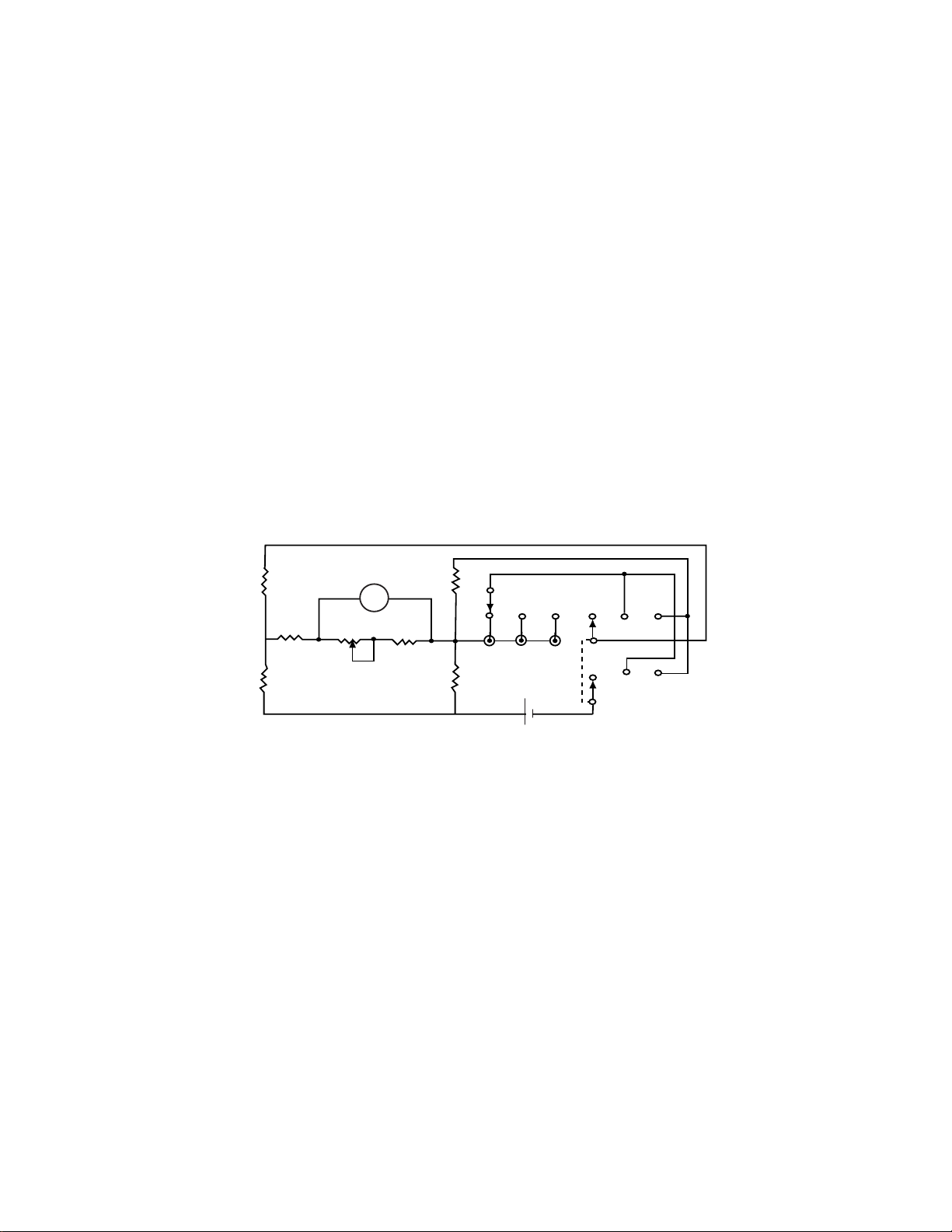
Figure 5-1. Wiring Diagram
NOTES:
Unless specified, resistors are in Ohms
Switches show in extreme counter clockwise
SW1 Probe selector
SW2 Function selector
+¯
+¯
B1
1.5V
23
789
123
C
SW2
A
SW1
R3
7560
5100
50K
9250
R2
7560
R4 R7 R5
R1
57.7K
M1
50AR6
3310
2100⍀
A
1

12
SIMPSON ELECTRIC COMPANY 853 Dundee Avenue
Elgin, IL 60120-3090 (847) 697-2260 FAX (847) 697-2272
Printed in U.S.A. Part No. 06-114985 Edition 4, 10/02
Visit us on the web at: www.simpsonelectric.com
This manual suits for next models
1
Table of contents
Other Simpson Test Equipment manuals


